2008 AUDI S6 ECU
[x] Cancel search: ECUPage 104 of 390

• ..__S_ e_a _ t_ s_ a_ n_ d_ s_t _o _r_ a-' g==- e ________________________________________________ _
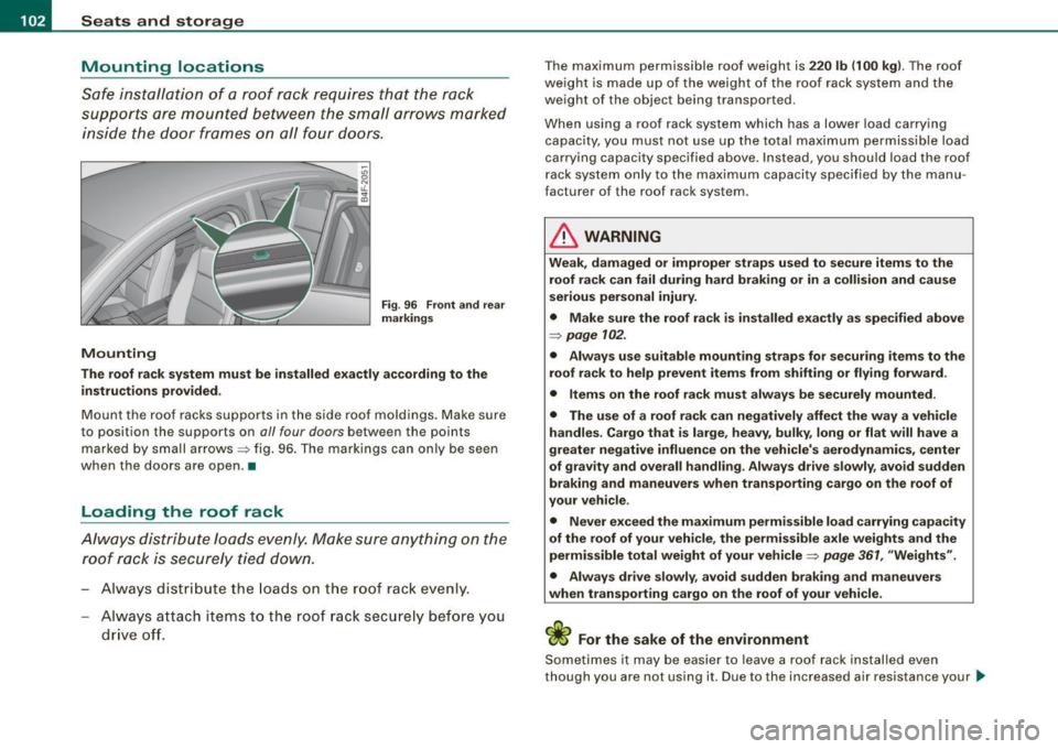
Mounting locations
Safe installation of a roof rack requires that the rack
supports are mounted between the small arrows marked inside the door frames on all four doors.
/4
Mounting
Fig . 96 Front and rear
markings
The roof rack system must be installed exactly according to the
instructions provided .
Mount the roof racks supports in the side roof moldings. Make sure
to position the supports on
all four doors between the points
marked by small arrows~ fig. 96. The markings can only be seen
when the doors are open . •
Loading the roof rack
Always distribute loads evenly. Make sure anything on the
roof rack is securely tied down.
- Always distribute the loads on the roof rack even ly.
Always attach items to the roof rack securely before you
drive off.
The maximum perm issible roof weight is 220 lb (100 kg). The roof
weight is made up of the weight of the roof rack system and the
weight of the object being transpor ted.
When using a roof rack system which has a lower load carrying
capacity, you must not use up the total maximum permissible load
carrying capaci ty specified above. Instead, you should load the roof
rack system only to the maximum capacity specified by the manu
facturer o f the roof rack syst em .
& WARNING
Weak, damaged or improper straps used to secure items to the
roof rack can fail during hard braking or in a collision and cause
serious personal injury.
• Make sure the roof rack is installed exactly as specified above
=> page 102.
• Always use suitable mounting straps for securing items to the
roof rack to help prevent items from shifting or flying forward.
• Items on the roof rack must always be securely mounted .
• The use of a roof rack can negatively affect the way a vehicle
handles . Cargo that is large, heavy, bulky, long or flat will have a
greater negative influence on the vehicle's aerodynamics, center
of gravity and overall handling . Always drive slowly, avoid sudden
braking and maneuvers when transporting cargo on the roof of
your vehicle.
• Never exceed the maximum permissible load carrying capacity
of the roof of your vehicle, the permissible axle weights and the
permissible total weight of your vehicle=>
page 361, "Weights".
• Always drive slowly, avoid sudden braking and maneuvers
when transporting cargo on the roof of your vehicle.
For the sake of the environment
Sometimes it may be easier to leave a roof rack installed even
though you are not using it. Due to the increased air resis tance your _..
Page 105 of 390

________________________________________________ S_e_ a_ ts_ a_ n_d _ s_t _o _r_ a ....; g::;. e _ __.1!111
vehicle will unnecessarily use more fuel. Remove the roof rack if you
are not going to use it.•
Cupholder
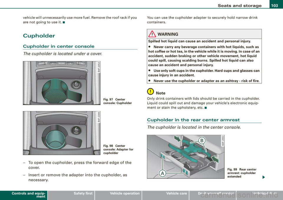
Cupholder in center console
The cupholder is located under a cover.
.. . .
..
. '
' '
. ' . '
. . ' ' .. . '
' ' . . . . . '
' . ..
'' N . . "' : : ~ : : t1.
: : ;g
' '
' .
' • a, •• 0 : : ~ ' ' ' ' lL : : ~
.. . '
.. . . . .
. . ' ' . '
Fig . 97 Center
console: Cupholder
Fig . 98 Center
console: Adapter for
cupholder
- To open the cupholder, press the forward edge of the
cover.
- Insert or remove the adapter into the cupholder, as
necessary.
Con tro ls and eq uip·
ment
You can use the cupholder adapter to securely hold narrow drink
containers.
& WARNING
Spilled hot liquid can cause an accident and personal injury.
• Never carry any beverage containers with hot liquids, such as
hot coffee or hot tea, in the vehicle while it is moving. In case of an
accident, sudden braking or other vehicle movement, hot liquid
could spill, causing scalding burns. Spilled hot liquid can also
cause an accident and personal injury .
• Use only soft cups in the cupholder. Hard cups and glasses can
cause injury in an accident.
• Never use the cupholder or adapter as an ashtray • risk of fire .
0 Note
Only drink containers with lids should be carried in the cupholder.
Liquid could spill out and damage your vehicle's electronic equip ·
mentor stain the upholstery, etc. •
Cupholder in the rear center armrest
The cupholder is located in the center console .
Vehicle care I I
Fig. 99 Rear center
armrest: cupholder
extended
irechnical data
Page 110 of 390

• ..__S_ e_a _ t_ s_ a_ n_ d_ s_t _o _r_ a-' g==- e ________________________________________________ _
& WARNING
To reduce the risk of personal injury in an accident or sudden stop,
always keep the glove compartment closed while driving.
[ i J Tips
Should you not be able to open the glove compartment as
described, make sure the valet key function is not activated
=> page 51. •
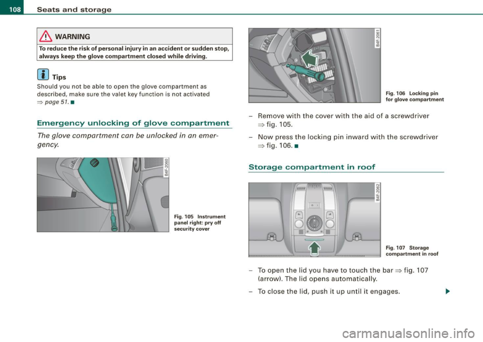
Emergency unlocking of glove compartment
The glove compartment can be unlocked in an emer
gency.
Fig. 105 Instrument
panel right : pry off
security cover
Fig. 106 Locking pin
for glove compartment
- Remove with the cover with the aid of a screwdriver
=> fig. 105.
- Now press the locking pin inward with the screwdriver
=> fig. 106. •
Storage compartment in roof
~1 0 I
G
0
••
8
"' iL
"' a,
Fig. 107 Storage
compartment in roof
- To open the lid you have to touch the bar=> fig. 107
(arrow). The lid opens automatically.
- To close the lid, push it up until it engages.
Page 130 of 390

• .___O_ n_ t_h _e _ r_o _a_ d __________________________________________________ _
& WARNING
• Never turn off the engine until the vehicle has come to a
complete stop.
• The brake booster and servotronic only work when the engine
is running. With the ignition turned off, you have to apply more
force when steering or braking. Since you cannot steer and stop
normally, this can lead to accidents and serious injuries.
• For safety reasons, you should always park your vehicle with
the selector lever in P. Otherwise, the vehicle could inadvertently roll away.
• After the engine has been switched off, the radiator fan can
continue to run for up to 10 minutes -even with the ignition
switched off. It can also switch on again after some time if the
coolant temperature rises as the result of a heat buildup or if the
engine is hot and the engine compartment is additionally heated
by the sun's rays.
0 Note
If the engine has been under heavy load for an extended period,
heat builds up in the engine compartment after the engine is
switched off -there is a risk of damaging the engine. Allow the
engine to run at idle for about 2 minutes before switching it off. •
Applies to vehicles: w ith Advanced Key
Driver messages in the instrument cluster
display
If a function is not present, a driver message appears.
No key identified
This message appears when the [STAR T) button is pressed if there
is no master key inside the vehicle or if the system does not recog
nize it. For example, the master key cannot be recognized if it is
covered by an object (e.g. aluminum brief case) which
screens the radio signal.
.Electronic devices such as cell phones can also inter
fere with the radio signal.
Press brake pedal to start engine
This message appears if you press the [ START) button to start the
engine and do not depress the brake pedal. The engine can only be
started if the brake pedal is depressed.
Engage N or P to start engine
This message appears when the engine is started if the selector
lever for the automatic transmission is not in the P or N position.
The engine can only be started with the selector in these positions.
? Key not in vehicle
This message appears along with the symbol if the master key is
removed from the vehicle with the engine running. It is intended to
remind you (e.g. when changing drivers) not to continue the journey
without the master key.
If the master key is no longer in the vehicle, you cannot switch off
the ignition after stopping the engine and you also cannot start the engine again. Moreover, you cannot lock the vehicle from the
outside with the key.
Shift to P, otherwise vehicle can roll away. Doors do not lock if lever
is not in
P.
This message appears for safety reasons along with a warning
buzzer if the selector lever for the automatic transmission is not in
the P position when the ignition is switched off with the
[STOP)
button and the driver's door is opened. Move the selector lever to
the P position, otherwise the vehicle is not secured against rolling
away. You also cannot lock the vehicle using the locking button on
the door handle or using the remote key.
To engage steering lock, press and hold STOP button
This message appears for safety reasons if the engine and the igni
tion have been switched off by pressing the [
STOP) button once, .,,_
Page 156 of 390

....... __ A_u_ t_o _m_ a_ t_ ic_ t_ r_a _ n_ s_m _ i_s _s _i_o _n ________________________________________________ _
The selector lever must be in Nor P. If one of the driving positions
is engaged a safe ty switch will prevent the engine from bei ng
started . See also=:> page 125 .
Before you move the selector lever from the
P position, you must
a lways apply the brake peda l be fore and wh ile depress ing the
button in the hand le of the selector lever .
& WARNING
• Unintended vehicle movement can cause serious injury .
- When the selector lever is in a driving po sition , the vehicle
m ay creep , even at idle speed . Therefore do not release the
parking brake or foot brake until you are ready to move ,
be cause power i s tran smitted to the wheels as soon as a
driving position is engaged .
- Do not accelerate wh ile se le cting a driving position . At th is
t ime the engine must be at idle speed so that undue stre ss is
not pla ced on the clut che s in the tr ansmission .
- Remember : - even when stopped briefly with the automatic
tr ansmission in "D ", "S " or "R ", engine po wer i s bei ng tran s
mitted to the whe els. Y our vehicle could "c reep " forward or
ba ckward. When stopped , keep the brake pedal fully depre ssed
and u se the parking brake if nece ssary to keep the vehicle from
rolling .
• If the selector lever is unintentionally moved into N while you
are driving , take yo ur foot off the a ccelerator pedal and wait fo r
the engine to return to id le speed before selecting a driving posi
t ion .
• Never shift into "R " or "P " when the vehicle i s in motion .
• Never get out of the driver 's seat when the engine is runnin g.
• If you must get out of the veh icle, move the selector le ver
se curely into the P position and appl y the park ing brake firmly .
• If the engine must remain running , ne ver have any dr iving po si
tion engaged when che cking under the hood . Make sure the
s electo r le ver has securel y eng aged and i s lo cked in "P " with the
& WAR NING (continued )
parking brake firmly set=> page 289 , "Engine compartment ".
Otherwi se , any increase in engine speed may set the vehicle in
motion , even w ith the park ing bra ke applied . •
App lies to vehicles: with 6-speed automatic t ransmission
Selector lever positions
This sec tion describes the select or lever p ositions and
drivin g ra nges.
Fi g. 1 51 D isplay i n the
in strument clu ster :
s ele ctor lev er in po si
t ion D
T he se lec tor leve r posi tion engaged appea rs next to the selector
lever as we ll as in the instrument c luster disp lay .
P -Park
In this selector lever position the transmission is mechanically
l ocked. Engage
P on ly when the vehicle is completely stopped=> &
in "Driving the automatic transmission" on page 153.
To shift in or out of positio n
P, you must first press and hold the
brake peda l and then press the release button in the se lector lever
handle while moving the selector lever to or from
P . You can shif t
out o f this pos ition only with the ignition on.
~
Page 163 of 390

Automatic transmission 1111111 __________________________ ___;__:..;____;_ ______ _
& WARNING (continued )
-When the selector lever is in a driving position , the vehi cle
may creep , even at idle speed . Therefore do not release the
parking brake or foot brake until you are ready to move ,
because power is transmitted to the wheels as soon as a
driving position is engaged.
- Do not accelerate while selecting a driving position. At this
time the engine must be at idle speed so that undue stress is
not placed on the clutches in the transmission.
- Remember : - even when stopped briefly with the automatic
transmission in "D", "S" or "R" , engine power is being trans
mitted to the wheels . Your vehicle could "creep " forward or
backward . When stopped , keep the brake pedal fully depressed
and use the parking brake if necessary to keep the vehicle from
rolling .
- If the sele ctor lever is unintentionally moved into N while you
are driving , take your foot off the accelerator pedal and wait for
the engine to return to idle speed before selecting a driving
position .
- Never shift into "R " or "P " when the vehicle is in motion .
- Never get out of the driver's seat when the engine is running.
- If you must get out of the vehicle , move the selector lever
securely into the P position and apply the parking brake firmly .
- If the engine must remain running, never have any driving
position engaged when checking under the hood. Make sure
the selector lever has securely engaged and is locked in "P "
with the parking brake firmly set :::::, page 289, "Engine
compartment ". Otherwise , any increase in engine speed may
set the vehicle in motion , even with the parking brake
applied .•
Controls and equip
ment
Ap plies to vehic les : wit h m ultit ron ic® Conti nuous ly Va riable Transm ission (CVT)
Selector lever positions
This sec tion des cribes th e sele ctor lev er positi ons an d
dr iv ing ra ng es.
Fig . 159 Display in the
instrument clu ster:
se lector lever in posi ·
tion P
Th e se lecto r le ver p ositi on engag ed app ear s ne xt to th e selec tor
lev er as well as in the instrument cluste r disp lay .
P -Park
In this s electo r lever position the transmission is mechanica lly
lo cke d.
Eng age P on ly when t he veh ic le is completely stopped=> 11::::. in
" Dr ivin g th e multitroni c®" on page 160
T o s hift int o or out o f pos ition P , you m ust fi rs t p ress a nd h old the
brake peda l and then press the r elease button in th e se lector lever
h an dle whi le m oving the sele ctor l ev er to P .
R - Reverse
The tra nsm issio n w ill automat ica lly se lect the lowest gear ratio
when you sh ift into reverse .
S ele ct R only wh en th e ve hicle is at a
fu ll sto p and t he engine is
running at id le speed :::::, 11::::. in "Driving t he multitron ic®" on
page 1 60.
I • •
Page 184 of 390

• .___A_ d_ a --=- p_t_ i_v _e _ A_ ir_ S_u_ s_,_ p_e_ n_ s_io _ n _____________________________________________ _
Adaptive Air Suspension
Adaptive Air Suspension and
Damping
A pplies to veh icles: with Adaptive Air Suspens ion
Description
Adaptive Air Suspension and damping can be regulated
and they adapt automatically to a request from the driver
and the driving situation at the time.
Adaptive Air Suspension is an electronically controlled springing
and damping system . Th is chassis system makes it easier on the
driver by adapting to the particular situation through imperceptible
control processes.
The
Adaptive Air Suspension component regulates ground clear
ance depending on vehicle speed, load condition and driver input.
When the system is in automatic mode, accelerating to a speed above a predetermined limit will make the vehicle lower itself. On
the other hand, driving more slowly results in the vehicle raising
again at specific speeds.
The
damping component provides individual control of the
damping forces. For example, with damping characteristics set to
provide greater comfort, damping is set somewhat harder for a brief
period only as required, for example, when going around a curve or
over rough road surfaces as well as when braking.
Settings
Adaptive Air Suspension provides the driver with the opportunity to
set the chassis characteristics also to their individual preference.
With the driving modes
standard, automatic and dynamic the driver
has three chassis settings available, ranging from comfort to sporty .
In addition,
lift provides a fourth mode which can be selecting for
driving over poor stretches of road :::::,
page 183, "Chassis controls". The modes are set in
MMI:::::,
page 183.
& WARNING
The height of the parked vehicle can change due to temperature
fluctuations or changes in load.
0 Note
• Whenever you park your vehicle, always make sure there is
adequate clearance above and below the vehicle. The height of the parked vehicle can change as the result of temperature fluctuations,
changes in load condition and changes in the driving mode (ground
clearance!.
• If the vehicle is being transported (e.g. by tow truck, train, ship,
etc.), mount the tie -down chains/cables over the running surface
(circumference) of the tires . Never secure the vehicle by the axle, the
suspension struts or the front or rear towline eye. For technical
reasons, the pressure in the suspension struts may change during
the transport, which could result in the vehicle no longer being
secured properly.
• To prevent damage to the vehicle underbody, remember that
your vehicle is not an off-road vehicle, even in the "lift" mode. The
ground clearance is insufficient for this type of operation.
• If you are going to tow a trailer, you must activate the trailer oper
ation mode :::::,
page 184.
[ i] Tips
Before you raising your vehicle using the vehicle jack (for example,
when changing a flat tire) you must activate the jacking mode
=> page 184. •
Page 191 of 390

___________________________________________________ H_ o_m_ e_ L_ i_ n _ k_ @_ R __ JIIII
Pro gra mmin g th e bump er mounted tr ansmitt er
1. Hold th e original remote control at a distance between 0 -
5 in. (0- 13 cm) from the bumper below the appropriate
headlight for your vehicle (use the shortest distance
poss ible).
2. Aim the remote control just below the pass enger side
headlight.
3. Press and hold the activation button on the remote
control.
4 . The emergency flashers will flash three t ime s (after
abo ut
15-60 seconds) w hen the programming is
successful. Now release the button on the remote
control.
- I f the device utilizes a ro lling code, please follow phase
3
of ~ page 186, "Programmi ng the Home Link® trans
mitter" for rolling code programming .
This pr oce dure w ill cause the ex ist ing prog ram ming on the
H om eli nk® butto n to be eras ed! •
Applies to vehicles: with Homelink® unive rsal remote contro l
Erasing the programming of the HomeLink ®
transmitter
When you erase the programming, the programming on
all three of the transmitter channels with be lost!
- Perform steps 1 to 4 as described on~ page 187 , "Phase
1: programming the overhead keypad".
When comp leted, the Homelink ® system wil l be in the program
ming mode and is then ready to learn the codes for remote
controlled devices.
Controls and equip
ment
[ i ] Tip s
• Programmed buttons cannot be erased indiv idual ly.
• For security reasons you are advised to erase the programming
of the Homelink® system before you sell your vehicle. •
Applies to veh icles : w ith Homelink® universal remote control
Information and accessories
If you wou ld like more information on Homelink ®, where to
purchase the Homelink® compatib le products, or would like to
purchase the Homelink ® Home Lighting Package, please cal l toll
free: 1-800-355-3515.
[ i ] Tip s
• The Homelink ® universal transmitter complies with part 15 of
the FCC rules and RSS -210 of IC part 15 . Operation is subject to the
following conditions :
- this device may not cause harmful interference, and
- this dev ice must accept any interference that may be received
inc luding interference that may cause undesired operation.
• Changes or modifications not express ly approved by the party
responsible for compliance could void the user's authority to
operate the device (DOC : ISTC 1763 102 264 Prince MODEUFCC ID :
CB2 V94800). •
I • •