2008 AUDI S5 boot
[x] Cancel search: bootPage 136 of 294
Downloaded from www.Manualslib.com manuals search engine Audi parking system 134•
To ensure that the acoustic parking aid works properly, the
sensors and the lens of the reversing camera must be kept clean
and free of snow and ice. Please observe the additional notes from
⇒page 143 onwards.
•
Please refer to the notes on towing ⇒page 138.
Applies to vehicles: with parking system advancedReversing camera (Rear View)
The reversing camera image in the MMI display shows the
area behind the vehicle.
Parking mode
There are two different parking modes available when you park your
vehicle with the help of the reversing camera. These are referred to
as “Parking mode 1” ⇒page 136 and “Pa r k i n g m od e 2” ⇒page 137.
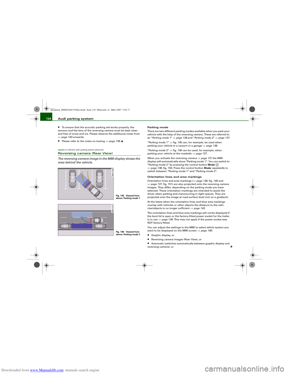
“Parking mode 1” ⇒fig. 145 can, for example, be used when
parking your vehicle in a carport or a garage ⇒page 136.
“Parking mode 2” ⇒fig. 146 can be used, for example, when
parking your vehicle at the roadside ⇒page 137.
When you activate the reversing camera ⇒page 131 the MMI
display will automatically show “Parking mode 1”. You can switch to
“Parking mode 2” by pressing the control button Mode
⇒page 136, fig. 150. Press the control button Mode repeatedly to
switch between “Parking mode 1” and “Parking mode 2”.
Orientation lines and area markings
Orientation lines and area markings (⇒page 136, fig. 149 and
⇒page 137, fig. 151) are also projected onto the reversing camera
images. They differ, depending on the parking mode you have
selected. These orientation markings are intended to assist the
driver when parking and manoeuvring in tight spaces. They are
projected onto the image at road surface level (not on a gradient).
At the latest when the orientation lines and blue area markings
overlap with vehicles or other objects the distance to the vehi-
cles/objects is no longer sufficient ⇒page 142.
The orientation lines and blue area markings will not be displayed if
the boot lid is open or the factory-fitted power socket for the trailer
is in use ⇒page 138. This may not apply if the power socket was
NOT factory-fitted.
You can adjust the settings in the MMI to select which system you
want to be displayed on the MMI screen ⇒page 140:•
Graphic display, or
•
Reversing camera images (Rear View), or
•
Automatic (switches automatically between graphic display and
reversing camera), or
Fig. 145 Viewed from
above: Parking mode 1Fig. 146 Viewed from
above: Parking mode 2
AA
document_0900452a81793dcc.book Seite 134 Mittwoch, 21. März 2007 5:42 17
Page 137 of 294
Downloaded from www.Manualslib.com manuals search engine Audi parking system135
Controls
Safety
Driving tips
General maintenance
Self-help
Technical data
•
Off (no display).
The reversing camera can be switched on and off in the MMI
⇒page 140. The acoustic proximity warning will, however, remain
activated.
WARNING
•
The reversing camera has blind spots in which obstacles are
not registered. It is particularly important to ensure that there are
no small children or animals near the vehicle, as the reversing
camera may not always be able to detect them (accident risk).
•
The parking aid cannot replace the full concentration of the
driver. The driver is always responsible for safety during parking
and other manoeuvres. Always keep a close watch on the area
around the vehicle.
•
Please note that low obstacles detected by the system may no
longer be registered by the sensors as the car moves closer, so the
system will not give any further warning. Certain kinds of obsta-
cles (such as wire fences, chains, thin painted posts or trailer draw
bars, etc.) may not always be detected by the system (accident
risk).Note
•
There is a slight delay in the picture display.
•
To ensure that the reversing camera works properly, the lens of
the camera ⇒page 131, fig. 143 must be kept clean and free of
snow and ice. Please observe the additional notes on ⇒page 143.
•
If the boot lid is open the angle covered by the camera will
change. For this reason, the image of the reversing camera will then
be shown without orientation lines and blue area markings.
•
Please refer to the notes on towing ⇒page 138.
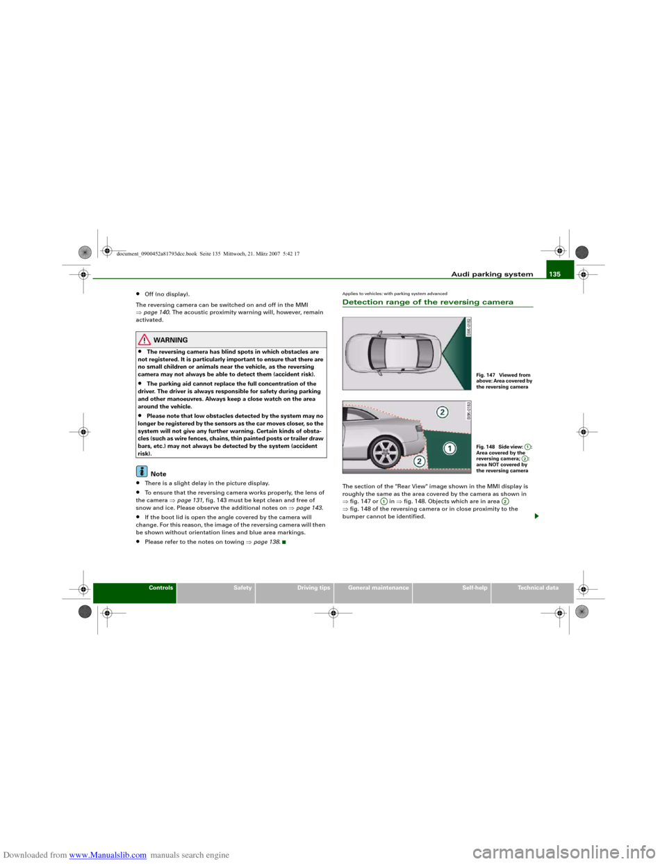
Applies to vehicles: with parking system advancedDetection range of the reversing cameraThe section of the "Rear View" image shown in the MMI display is
roughly the same as the area covered by the camera as shown in
⇒fig. 147 or in ⇒fig. 148. Objects which are in area
⇒fig. 148 of the reversing camera or in close proximity to the
bumper cannot be identified.
Fig. 147 Viewed from
above: Area covered by
the reversing cameraFig. 148 Side view: :
Area covered by the
reversing camera; :
area NOT covered by
the reversing camera
A1A2
A1
A2
document_0900452a81793dcc.book Seite 135 Mittwoch, 21. März 2007 5:42 17
Page 146 of 294
Downloaded from www.Manualslib.com manuals search engine Audi parking system 144•
Do not allow the camera images in the MMI display to distract
you from watching the traffic.
•
When parking or manoeuvring do not rely solely on the MMI
display. Some objects (e.g. narrow posts or bars) may - due to the
resolution of the display screen - not be displayed in a satisfactory
manner or may not be displayed at all.
•
Only use the reversing camera to assist you if it is supplying
you with a good and clear picture. The quality of the picture could
be impaired by adverse light, dirt on the lens or a defect (accident
risk).
•
If the MMI display is switched on and the picture is obscured or
the area behind the vehicle is not visible (e.g. due to a dirty or
defective lens) you must not use the reversing camera to assist
you when manoeuvring (accident risk).
•
The reversing camera produces two-dimensional images.
Please remember that ridges in the ground, parts protruding on
other vehicles or fixed objects jutting out are all more difficult to
detect on the MMI display screen due to a lack of spatial depth. In
some cases it may not be possible to detect them at all.
•
For safety reasons, you should not use the system if the posi-
tion and installation angle of the camera have been changed, e.g.
in a rear-end collision. Have it checked by a qualified workshop.
•
Only use the reversing camera when the boot lid is completely
c lo s e d . P l e a se m a k e su re t h a t t here are no objects mounted to the
rear end of the vehicle which could block the view of the reversing
camera.Caution
•
Never remove snow and ice from the lens of the reversing
camera using warm or hot water - danger of cracks appearing on the
lens.
•
Never use abrasive cleaning agents on the lens.WARNING (continued)
document_0900452a81793dcc.book Seite 144 Mittwoch, 21. März 2007 5:42 17
Page 160 of 294
Downloaded from www.Manualslib.com manuals search engine Safe driving 158
WARNING
Any obstructions that restrict pedal travel can cause loss of
vehicle control and critical situations on the road.•
Never place objects in the driver's footwell. Such objects could
move under the pedals and interfere with their proper function. In
the event of sudden braking or a change of direction, you would
not be able to use the pedals. This could result in a loss of control
and possibly cause an accident.
Floor mats on the driver's side
Use only floor mats which can be securely fastened in the
footwell and do not obstruct the pedals.– Make sure that floor mats are securely fastened and
cannot interfere with the pedals ⇒.Use only floor mats that leave the pedal area unobstructed and are
firmly secured to prevent them from slipping. You can obtain suit-
able floor mats from your dealer or a specialist retailer.
WARNING
Any obstructions that restrict pedal travel can cause loss of
vehicle control and increase the risk of serious personal injury. •
Always make sure that floor mats are properly secured.
•
Never lay or install additional floor mats or other floor cover-
ings over the existing floor mats; this would restrict the pedal area
and possibly obstruct the pedals, which could cause an
accident.
Stowing luggage safelyLuggage compartment
All luggage and other objects must be safely secured in
the luggage compartment.Loose items in the luggage compartment can shift suddenly
and cause a safety hazard or impair the handling of the
vehicle by changing the weight distribution.
– Distribute the load evenly in the luggage compartment
⇒page 75.
– Place heavy items as far forward as possible in the
luggage compartment and secure them properly.
– Use the fastening rings* provided ⇒page 159 or the
luggage net* for securing heavy items.
WARNING
•
Loose items in the luggage compartment can shift suddenly
and cause a safety hazard or impair the handling of the vehicle by
changing the weight distribution.
•
Always stow objects in the luggage compartment and secure
them on the fastening rings*.
•
Transporting heavy objects may affect the vehicle's handling by
shifting the centre of gravity – this could cause an accident. Take
extra care when driving and adjust your speed accordingly.
•
Never exceed the maximum axle loads or the maximum gross
weight for the vehicle ⇒page 281, “Performance, weights and
dimensions”. Exceeding the permitted axle loads or gross weight
limit can affect the vehicle's handling characteristics, and increase
the risk of accidents, personal injuries or damage to the vehicle.
•
Never leave your vehicle unattended when the boot lid is open.
Children could climb into the boot and close the boot lid from the
document_0900452a81793dcc.book Seite 158 Mittwoch, 21. März 2007 5:42 17
Page 161 of 294
Downloaded from www.Manualslib.com manuals search engine Safe driving159
Controls
Safety
Driving tips
General maintenance
Self-help
Technical data inside. In this case the child would be unable to get out of the
vehicle without help. This could have fatal consequences.
•
Never allow children to play in or around the vehicle. Always
close and lock the boot lid and all the doors when you leave the
vehicle.
•
Never let passengers ride in the luggage compartment. All
occupants must be properly restrained by the seat belts at all
times ⇒page 160.Note
•
Air circulation in the vehicle helps reduce fogging of the
windows. Used air escapes through ventilation slots in the rear of
the vehicle. Make sure that these ventilation slots are not
obstructed.
•
Suitable belts for securing loads to the fastening rings* are
commercially available.
Applies to vehicles: with fastening ringsFastening rings
Unsecured loads are a hazard to all vehicle occupants.There are fastening rings in the luggage compartment
which can be used to secure luggage and other objects
⇒page 76.
– Use the fastening rings to secure items safely in the
luggage compartment ⇒ in “Loading the luggage
compartment” on page 75.During a collision or an accident, even small and light objects can
possess so much energy that they can cause very severe injuries.
The amount of this “kinetic energy” depends on the speed of the vehicle and the weight of the object. The most significant factor,
however, is the speed of the vehicle.
An example: An object weighing 4.5 kg is lying unsecured in the
vehicle. During a frontal collision at a speed of 50 km/h, this object
generates a force corresponding to 20 times its weight. That means
that the effective weight of the object increases to about 90 kg. You
can imagine the severity of the injuries which might be sustained if
this “projectile” strikes an occupant as it flies through the
passenger compartment.
WARNING
If items of luggage or other objects are secured to the fastening
rings with inappropriate or damaged retaining cords, injuries
could result in the event of sudden braking or a collision.•
To prevent pieces of luggage or other objects from flying
forward, always use appropriate retaining cords which are prop-
erly secured to the fastening rings.
•
Never secure a child seat on the fastening rings.
WARNING (continued)
document_0900452a81793dcc.book Seite 159 Mittwoch, 21. März 2007 5:42 17
Page 246 of 294
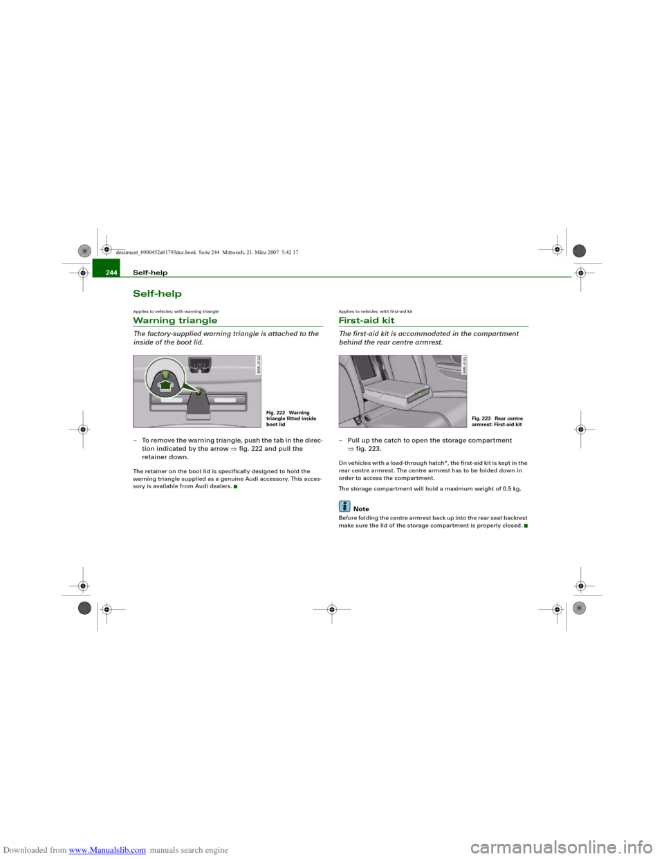
Downloaded from www.Manualslib.com manuals search engine Self-help 244Self-helpApplies to vehicles: with warning triangleWarning triangleThe factory-supplied warning triangle is attached to the
inside of the boot lid.– To remove the warning triangle, push the tab in the direc-
tion indicated by the arrow ⇒fig. 222 and pull the
retainer down.The retainer on the boot lid is specifically designed to hold the
warning triangle supplied as a genuine Audi accessory. This acces-
sory is available from Audi dealers.
Applies to vehicles: with first-aid kitFirst-aid kitThe first-aid kit is accommodated in the compartment
behind the rear centre armrest.– Pull up the catch to open the storage compartment
⇒fig. 223.On vehicles with a load-through hatch*, the first-aid kit is kept in the
rear centre armrest. The centre armrest has to be folded down in
order to access the compartment.
The storage compartment will hold a maximum weight of 0.5 kg.
Note
Before folding the centre armrest back up into the rear seat backrest
make sure the lid of the storage compartment is properly closed.
Fig. 222 Warning
triangle fitted inside
boot lid
Fig. 223 Rear centre
armrest: First-aid kit
document_0900452a81793dcc.book Seite 244 Mittwoch, 21. März 2007 5:42 17
Page 248 of 294
Downloaded from www.Manualslib.com manuals search engine Self-help 246If you need the tools, the Tyre Mobility System or the jack*, you will
have to open the floor panel and take out the spare wheel*
⇒page 246.
The tool kit includes:•
A hook for removing hub caps
•
Pin for mounting a wheel
•
Screwdriver with reversible blade
•
Tool for changing bulbs
•
Interchangeable socket (Torx socket for changing bulbs)
•
Crank handle for jack
•
Adapter for anti-theft wheel bolts*
•
Jack*
•
Box spanner for wheel bolts
•
Towline anchorage
Some of the parts listed are only fitted on certain models or are
optional extras.
Before stowing the jack* again, wind down the arm of the jack as far
as it will go.
WARNING
•
Do not use the hexagonal socket in the screwdriver handle to
tighten the wheel bolts. It is not possible to tighten the bolts with
the required torque – risk of accident.
•
The jack supplied by the factory is only designed for changing
wheels on this model. On no account attempt to use it for lifting
heavier vehicles or other loads – risk of injury.
•
Never start the engine when the vehicle is on the jack - risk of
accident.
•
If work has to be done under the veh i cl e , e n su re t h a t i t is sa fe l y
supported on stands designed for the purpose, otherwise there is
a risk of injury.
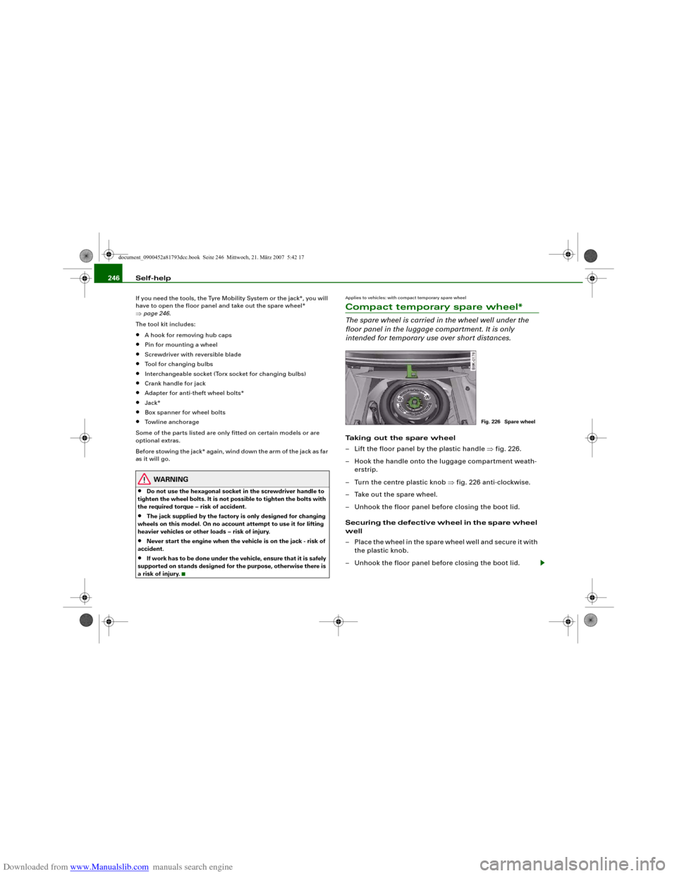
Applies to vehicles: with compact temporary spare wheelCompact temporary spare wheel*The spare wheel is carried in the wheel well under the
floor panel in the luggage compartment. It is only
intended for temporary use over short distances.Taking out the spare wheel
– Lift the floor panel by the plastic handle ⇒fig. 226.
– Hook the handle onto the luggage compartment weath-
erstrip.
– Turn the centre plastic knob ⇒fig. 226 anti-clockwise.
– Take out the spare wheel.
– Unhook the floor panel before closing the boot lid.
Securing the defective wheel in the spare wheel
well
– Place the wheel in the spare wheel well and secure it with
the plastic knob.
– Unhook the floor panel before closing the boot lid.
Fig. 226 Spare wheel
document_0900452a81793dcc.book Seite 246 Mittwoch, 21. März 2007 5:42 17
Page 263 of 294
Downloaded from www.Manualslib.com manuals search engine Fuses and bulbs261
Controls
Safety
Driving tips
General maintenance
Self-help
Technical data
Fuses and bulbsFusesChanging a fuse
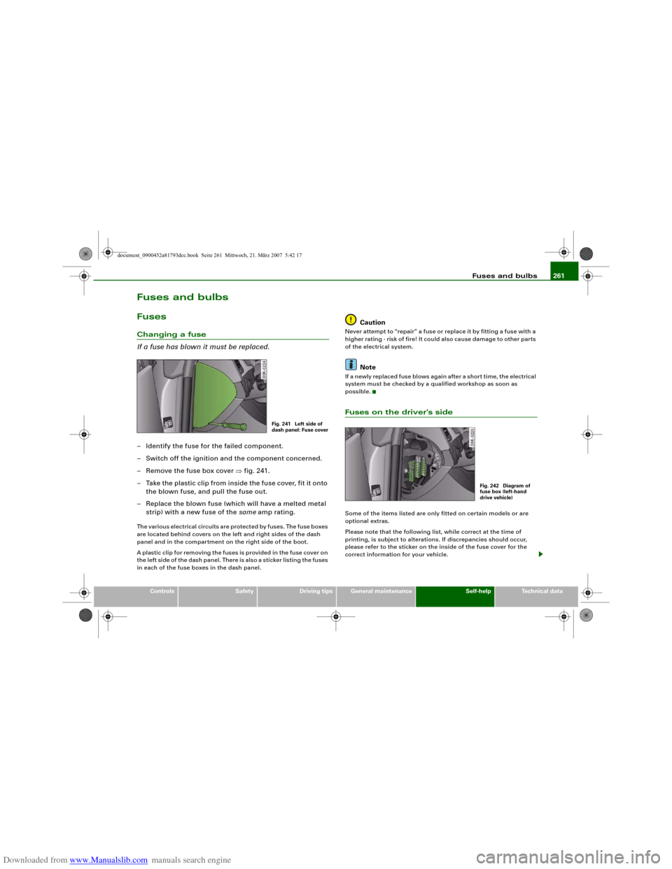
If a fuse has blown it must be replaced.– Identify the fuse for the failed component.
– Switch off the ignition and the component concerned.
– Remove the fuse box cover ⇒fig. 241.
– Take the plastic clip from inside the fuse cover, fit it onto
the blown fuse, and pull the fuse out.
– Replace the blown fuse (which will have a melted metal
strip) with a new fuse of the same amp rating.The various electrical circuits are protected by fuses. The fuse boxes
are located behind covers on the left and right sides of the dash
panel and in the compartment on the right side of the boot.
A plastic clip for removing the fuses is provided in the fuse cover on
the left side of the dash panel. There is also a sticker listing the fuses
in each of the fuse boxes in the dash panel.
Caution
Never attempt to “repair” a fuse or replace it by fitting a fuse with a
higher rating - risk of fire! It could also cause damage to other parts
of the electrical system.
Note
If a newly replaced fuse blows again after a short time, the electrical
system must be checked by a qualified workshop as soon as
possible.Fuses on the driver's sideSome of the items listed are only fitted on certain models or are
optional extras.
Please note that the following list, while correct at the time of
printing, is subject to alterations. If discrepancies should occur,
please refer to the sticker on the inside of the fuse cover for the
correct information for your vehicle.
Fig. 241 Left side of
dash panel: Fuse cover
Fig. 242 Diagram of
fuse box (left-hand
drive vehicle)
document_0900452a81793dcc.book Seite 261 Mittwoch, 21. März 2007 5:42 17