2008 AUDI A5 steering
[x] Cancel search: steeringPage 137 of 313
Automatic gearbox135
Controls
Safety
Driving tips
General maintenance
Self-help
Technical data When the vehicle slows down (for instance when braking), the
gearbox automatically shifts down into the next gear when the
minimum engine speed is reached.
Changing down to a lower gear increases the engine braking effect
on downhill gradients.
When the accelerator pedal is pressed right down past the point of
resistance at full throttle, the gearbox will select a lower gear,
depending on road speed and engine speed.
Applies to vehicles: with multitronic®Back-up programme
A back-up system is in place should a fault occur in the
control system.The automatic gearbox switches to the back-up programme if a fault
should occur in the control system. This is indicated by all segments
of the display panel either lighting up together or going out
completely.
It is still possible to move the selector lever to all positions. The
manual shift programme (tiptronic) is not available when the back-
up programme is active.
It will still be possible to use reverse gear in the normal way.
However, the electronic lock for reverse gear will be switched off.
Caution
Should the gearbox ever switch into the back-up programme, you
should take the vehicle to an Audi dealer or qualified workshop as
soon as possible.
Applies to vehicles: Tiptronic controls on steering wheelSteering wheel with tiptronic controls
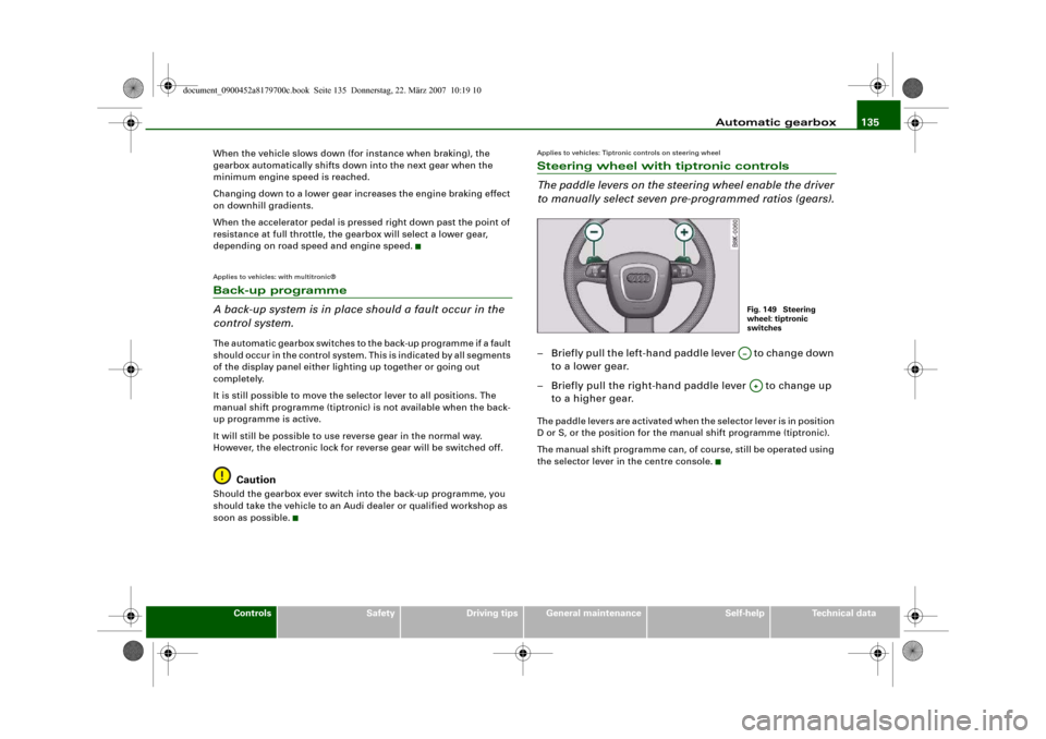
The paddle levers on the steering wheel enable the driver
to manually select seven pre-programmed ratios (gears).– Briefly pull the left-hand paddle lever to change down
to a lower gear.
– Briefly pull the right-hand paddle lever to change up
to a higher gear.The paddle levers are activated when the selector lever is in position
D or S, or the position for the manual shift programme (tiptronic).
The manual shift programme can, of course, still be operated using
the selector lever in the centre console.
Fig. 149 Steering
wheel: tiptronic
switchesA…A+
document_0900452a8179700c.book Seite 135 Donnerstag, 22. März 2007 10:19 10
Page 147 of 313
Audi parking system145
Controls
Safety
Driving tips
General maintenance
Self-help
Technical data
WARNING
Please note that objects which are not touching the ground may
appear to be further away than they actually are (e.g. the bumper
of a parked vehicle, a towing bracket or the rear end of a truck). In
this case you should not use the orientation lines for judging the
distance (accident risk).Applies to vehicles: with parking system advancedParking mode 1
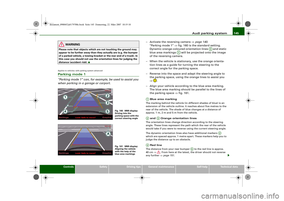
“Parking mode 1” can, for example, be used to assist you
when parking in a garage or carport.
– Activate the reversing camera ⇒page 140.
“Parking mode 1” ⇒fig. 160 is the standard setting.
Dynamic orange-coloured orientation lines and static
blue area markings will be projected onto the image
of the reversing camera.
– When the vehicle is stationary, use the orange orienta-
tion lines as a guide for turning the steering to the
correct angle for the parking space.
– Reverse into the space and adapt the steering angle to
the parking space, using the orange lines to assist you
⇒.
– Align your vehicle according to the blue area marking.
The blue area marking should be parallel to the lines of
the parking space ⇒fig. 161. Blue area marking
The marking behind the vehicle (in different shades of blue) is an
extension of the vehicle outline. It reaches about five metres to the
rear of the vehicle. The shade of blue changes at a distance of
approx. 1m, 2m and 5m from the vehicle.
and Orange orientation lines
The orientation lines change direction according to the steering
angle. These lines represent the path which the rear of the vehicle
would take if you were to reverse using the current steering angle.
The dynamic orientation lines also have additional markers
which are spaced approx. 1 metre apart. These markers help you to
judge the distance up to an obstacle.
Red line
The distance from your rear bumper to the red line is approx.
40 cm ⇒. From here at the latest, the driver should not reverse
any further ⇒page 151.
Fig. 160 MMI display:
Driving into the
parking space with the
correct steering angleFig. 161 MMI display:
Aligning the vehicle
with the help of the
blue area markings
A3
A1
A1A2
A3
A2
A4
A5
document_0900452a8179700c.book Seite 145 Donnerstag, 22. März 2007 10:19 10
Page 148 of 313
Audi parking system 146 Rear bumper
For better orientation the rear bumper of your vehicle is also shown
in the MMI display.
WARNING
Please note that objects which are not touching the ground may
appear to be further away than they actually are (e.g. the bumper
of a parked vehicle, a towing bracket or the rear end of a truck). In
this case you should not use the orientation lines for judging the
distance (accident risk).
Caution
The MMI display shows the path of the rear end of the vehicle if you
were to reverse using the current steering angle. NB: The front end
of the vehicle swings out further than the rear.
Note
•
To ensure that the reversing camera works properly, the lens of
the camera ⇒page 140, fig. 154 must be kept clean and free of
snow and ice. Please observe the additional notes on ⇒page 152.
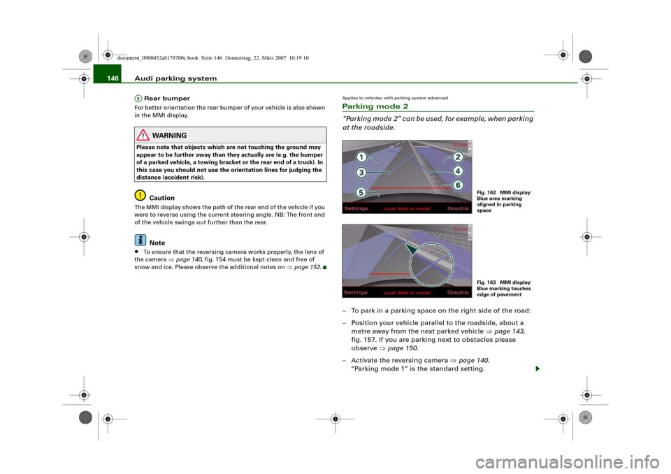
Applies to vehicles: with parking system advancedParking mode 2
“Parking mode 2” can be used, for example, when parking
at the roadside.– To park in a parking space on the right side of the road:
– Position your vehicle parallel to the roadside, about a
metre away from the next parked vehicle ⇒page 143,
fig. 157. If you are parking next to obstacles please
observe ⇒page 150.
– Activate the reversing camera ⇒page 140.
“Parking mode 1” is the standard setting.
A5
Fig. 162 MMI display:
Blue area marking
aligned in parking
spaceFig. 163 MMI display:
Blue marking touches
edge of pavement
document_0900452a8179700c.book Seite 146 Donnerstag, 22. März 2007 10:19 10
Page 149 of 313
Audi parking system147
Controls
Safety
Driving tips
General maintenance
Self-help
Technical data
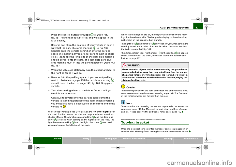
– Press the control button for Mode ⇒page 145,
fig. 161. “Parking mode 2” ⇒fig. 162 will appear in the
MMI display.
– Reverse and align the position of your vehicle in such a
way that the dark blue area marking ⇒fig. 162
borders onto the vehicle behind or onto the parking
space line marking. If you are not parking next to obsta-
cles ⇒page 150 the long side of the dark blue marking
should border onto the kerb. The complete dark blue
area marking must fit into the parking space ⇒page 143,
fig. 157.
– When the vehicle is stationary turn the steering wheel to
the right as far as it will go.
– Reverse into the parking space. If you are not parking
next to obstacles ⇒page 150 the dark blue marking
should touch the kerb ⇒page 146, fig. 163. Stop your
vehicle.
– Turn the steering wheel to the left as far as it will go
(vehicle is stationary).
– Continue to reverse into the parking space until the
vehicle is standing parallel to the kerb. When reversing
you must also keep a close watch on the front end of the
vehicle ⇒.You can use “Parking mode 2” to park on the left or the right side of
the road. For this reason, the blue markings are shown in various
shades of blue. The dark blue area marking and the dark blue
curve are used when parking on the right side of the road. The
light blue area marking and the light blue curve are used
when parking on the left side of the road.When the turn signals are on, the display will only show the mark-
ings for the relevant side. To change the display to the other side,
just switch on the opposite turn signals.
The light blue and dark blue cur v e s s h o w y o u w h e n t o t u r n t h e
steering wheel in the other direction, i.e. when the curve touches
the kerb. ⇒page 146, fig. 163.
The distance from your rear bumper to the red line is approx.
40 cm. From here at the latest, the driver should not reverse any
further ⇒page 151.
WARNING
Please note that objects which are not touching the ground may
appear to be further away than they actually are (e.g. the bumper
of a parked vehicle, a towing bracket or the rear end of a truck). In
this case you should not use the orientation lines for judging the
distance (accident risk).
Caution
The MMI display shows the path of the rear end of the vehicle if you
were to reverse using the current steering angle. NB: The front end
of the vehicle swings out further than the rear.
Note
To ensure that the reversing camera works properly, the lens of the
camera ⇒page 140, fig. 154 must be kept clean and free of snow
and ice. Please observe the additional notes on ⇒page 152.Applies to vehicles: with parking system and towing bracketTo w i n g b r a c k e tOnce the electrical connector for the trailer socket is plugged in on
vehicles with a factory-fitted towing bracket the rear sensors for the
AAA2
A4
A2
A4
A1
A3
A3
A4
A5
A6
document_0900452a8179700c.book Seite 147 Donnerstag, 22. März 2007 10:19 10
Page 164 of 313
Safe driving 162Safe drivingGeneral notesSafety is the first priority
Your safety is our first priority.This chapter contains important information, tips, sugges-
tions and warnings that you should read and observe for
your own safety and the safety of your passengers.
WARNING
•
The information in this chapter is important for the driver of
the vehicle and all passengers. The other chapters in this manual
(and, where applicable, in the other literature supplied with the
vehicle) contain further important notes which you should read
and observe for your own safety and that of your passengers.
•
Ensure that the complete vehicle wallet is always in the vehicle.
This is especially important when you lend or sell the vehicle to
others.
Safety features
The safety features listed here are part of the vehicle's
occupant restraint system. They work together to help
reduce the risk of injury in a wide variety of accident situ-
ations.Your safety and the safety of your passengers should not be left to
chance. In the event of an accident, the safety features incorporated
in your vehicle are capable of reducing the risk of injury. These are
just a few of the safety features in your Audi:•
Optimised three-point seat belts for all seats,
•
Belt force limiters for the front seats,
•
Belt pre-tensioners for the front seats,
•
Head restraints for all seats,
•
Optimised protection against injuries of the cervical vertebrae,
•
Front airbags,
•
Side airbags in the backrests of the front seats,
•
Head-protection airbags (sideguard system),
•
“ISOFIX” mountings* for “ISOFIX” child safety seats on the rear
seats,
•
Height-adjustable head restraints on the seats,
•
Adjustable steering column.
These individual safety features are harmonised to provide you and
your passengers with the best possible protection in accident situ-
ations. However, they can only be effective if you and your passen-
gers sit in the correct position and adjust and use the safety equip-
ment properly.
For these reasons, this chapter explains why these safety features
are so important, how they can protect you, what you need to
remember when using them, and how you and your passengers can
gain the most benefit from them. There are also a number of impor-
tant safety warnings which you and your passengers should always
observe in order to minimise the risk of injury.
Safety is everyone's responsibility!
Before every trip
The driver is responsible for the safety of the passengers
and the safe operation of the vehicle at all times.For your own safety and the safety of your passengers,
always note the following points before every trip:
document_0900452a8179700c.book Seite 162 Donnerstag, 22. März 2007 10:19 10
Page 166 of 313
Safe driving 164Correct sitting positionsCorrect sitting position for driver
The correct driving position is important for safe and
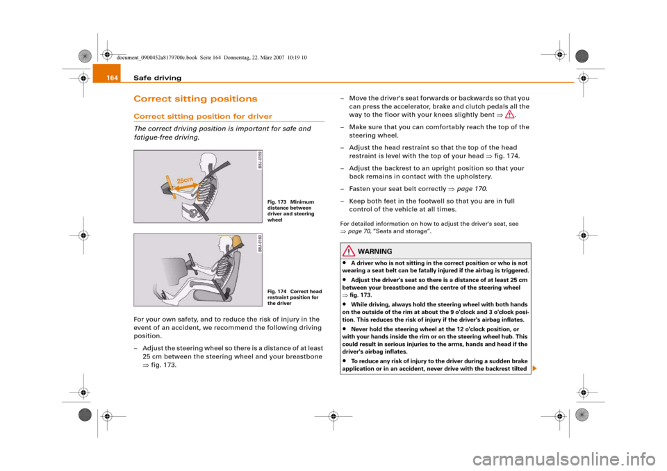
fatigue-free driving.For your own safety, and to reduce the risk of injury in the
event of an accident, we recommend the following driving
position.
– Adjust the steering wheel so there is a distance of at least
25 cm between the steering wheel and your breastbone
⇒fig. 173.– Move the driver's seat forwards or backwards so that you
can press the accelerator, brake and clutch pedals all the
way to the floor with your knees slightly bent ⇒.
– Make sure that you can comfortably reach the top of the
steering wheel.
– Adjust the head restraint so that the top of the head
restraint is level with the top of your head ⇒fig. 174.
– Adjust the backrest to an upright position so that your
back remains in contact with the upholstery.
– Fasten your seat belt correctly ⇒page 170.
– Keep both feet in the footwell so that you are in full
control of the vehicle at all times.
For detailed information on how to adjust the driver's seat, see
⇒page 70, “Seats and storage”.
WARNING
•
A driver who is not sitting in the correct position or who is not
wearing a seat belt can be fatally injured if the airbag is triggered.
•
Adjust the driver's seat so there is a distance of at least 25 cm
between your breastbone and the centre of the steering wheel
⇒fig. 173.
•
While driving, always hold the steering wheel with both hands
on the outside of the rim at about the 9 o'clock and 3 o'clock posi-
tion. This reduces the risk of injury if the driver's airbag inflates.
•
Never hold the steering wheel at the 12 o'clock position, or
with your hands inside the rim or on the steering wheel hub. This
could result in serious injuries to the arms, hands and head if the
driver's airbag inflates.
•
To reduce any risk of injury to the driver during a sudden brake
application or in an accident, never drive with the backrest tilted
Fig. 173 Minimum
distance between
driver and steering
wheelFig. 174 Correct head
restraint position for
the driver
document_0900452a8179700c.book Seite 164 Donnerstag, 22. März 2007 10:19 10
Page 174 of 313
Seat belts 172The physical principles involved in a frontal collision are relatively
simple:
Both the moving vehicle and the passengers possess energy, which
is known as “kinetic energy” ⇒page 171, fig. 178. The amount of
“kinetic energy” depends on the speed of the vehicle and the weight
of the vehicle and passengers. The higher the speed and the greater
the weight, the more energy there is to be absorbed in an accident.
The most significant factor, however, is the speed of the vehicle. If
the speed doubles from 25 km/h to 50 km/h, for example, the kinetic
energy increases by a factor of four. Because these passengers are
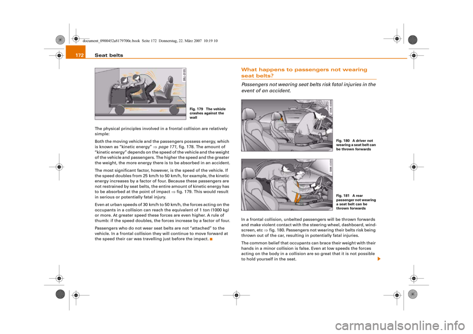
not restrained by seat belts, the entire amount of kinetic energy has
to be absorbed at the point of impact ⇒fig. 179. This would result
in serious or potentially fatal injury.
Even at urban speeds of 30 km/h to 50 km/h, the forces acting on the
occupants in a collision can reach the equivalent of 1 ton (1000 kg)
or more. At greater speed these forces are even higher. A rule of
thumb: if the speed doubles, the forces increase by a factor of four.
Passengers who do not wear seat belts are not “attached” to the
vehicle. In a frontal collision they will continue to move forward at
the speed their car was travelling just before the impact.
What happens to passengers not wearing seat belts?
Passengers not wearing seat belts risk fatal injuries in the
event of an accident.In a frontal collision, unbelted passengers will be thrown forwards
and make violent contact with the steering wheel, dashboard, wind-
screen, etc ⇒fig. 180. Passengers not wearing their belts risk being
thrown out of the car, resulting in potentially fatal injuries.
The common belief that occupants can brace their weight with their
hands in a minor collision is false. Even at low speeds the forces
acting on the body in a collision are so great that it is not possible
to hold yourself in the seat.
Fig. 179 The vehicle
crashes against the
wall
Fig. 180 A driver not
wearing a seat belt can
be thrown forwardsFig. 181 A rear
passenger not wearing
a seat belt can be
thrown forwards
document_0900452a8179700c.book Seite 172 Donnerstag, 22. März 2007 10:19 10
Page 180 of 313
Airbag system 178Front airbagsDescription of front airbags
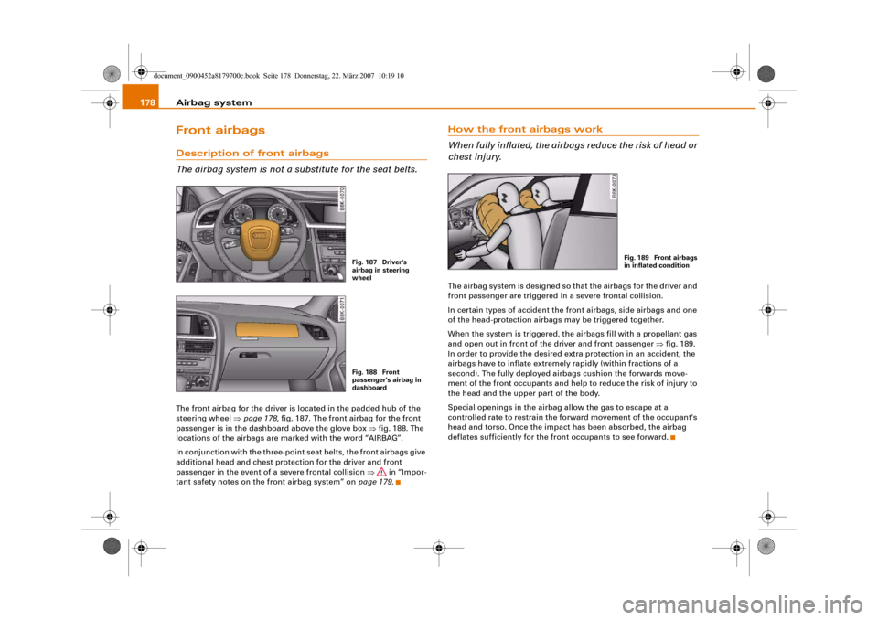
The airbag system is not a substitute for the seat belts.The front airbag for the driver is located in the padded hub of the
steering wheel ⇒page 178, fig. 187. The front airbag for the front
passenger is in the dashboard above the glove box ⇒fig. 188. The
locations of the airbags are marked with the word “AIRBAG”.
In conjunction with the three-point seat belts, the front airbags give
additional head and chest protection for the driver and front
passenger in the event of a severe frontal collision ⇒ in “Impor-
tant safety notes on the front airbag system” on page 179.
How the front airbags work
When fully inflated, the airbags reduce the risk of head or
chest injury.The airbag system is designed so that the airbags for the driver and
front passenger are triggered in a severe frontal collision.
In certain types of accident the front airbags, side airbags and one
of the head-protection airbags may be triggered together.
When the system is triggered, the airbags fill with a propellant gas
and open out in front of the driver and front passenger ⇒fig. 189.
In order to provide the desired extra protection in an accident, the
airbags have to inflate extremely rapidly (within fractions of a
second). The fully deployed airbags cushion the forwards move-
ment of the front occupants and help to reduce the risk of injury to
the head and the upper part of the body.
Special openings in the airbag allow the gas to escape at a
controlled rate to restrain the forward movement of the occupant's
head and torso. Once the impact has been absorbed, the airbag
deflates sufficiently for the front occupants to see forward.
Fig. 187 Driver's
airbag in steering
wheelFig. 188 Front
passenger's airbag in
dashboard
Fig. 189 Front airbags
in inflated condition
document_0900452a8179700c.book Seite 178 Donnerstag, 22. März 2007 10:19 10