Page 274 of 313

Fuses and bulbs 272Fuses and bulbsFusesChanging a fuse
If a fuse has blown it must be replaced.– Identify the fuse for the failed component.
– Switch off the ignition and the component concerned.
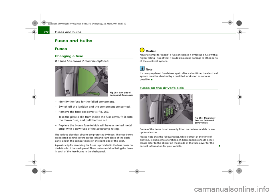
– Remove the fuse box cover ⇒fig. 253.
– Take the plastic clip from inside the fuse cover, fit it onto
the blown fuse, and pull the fuse out.
– Replace the blown fuse (which will have a melted metal
strip) with a new fuse of the same amp rating.The various electrical circuits are protected by fuses. The fuse boxes
are located behind covers on the left and right sides of the dash
panel and in the compartment on the right side of the boot.
A plastic clip for removing the fuses is provided in the fuse cover on
the left side of the dash panel. There is also a sticker listing the fuses
in each of the fuse boxes in the dash panel.
Caution
Never attempt to “repair” a fuse or replace it by fitting a fuse with a
higher rating - risk of fire! It could also cause damage to other parts
of the electrical system.
Note
If a newly replaced fuse blows again after a short time, the electrical
system must be checked by a qualified workshop as soon as
possible.Fuses on the driver's sideSome of the items listed are only fitted on certain models or are
optional extras.
Please note that the following list, while correct at the time of
printing, is subject to alterations. If discrepancies should occur,
please refer to the sticker on the inside of the fuse cover for the
correct information for your vehicle.
Fig. 253 Left side of
dash panel: Fuse cover
Fig. 254 Diagram of
fuse box (left-hand
drive vehicle)
document_0900452a8179700c.book Seite 272 Donnerstag, 22. März 2007 10:19 10
Page 276 of 313

Fuses and bulbs 274Fuses on the passenger's sideSome of the items listed are only fitted on certain models or are
optional extras.
Please note that the following list, while correct at the time of
printing, is subject to alterations. If discrepancies should occur,
please refer to the sticker on the inside of the fuse cover for the
correct information for your vehicle.
The seats with electrical adjustment are protected by circuit
breakers. These reset automatically after a few seconds when the
overload has been corrected.
Fuse listFuse listNo.
Electrical equipment
amps
Fuse carrier (black)1
Vacant
2
Vacant
3
Vacant
4
Vacant
5
Steering column switch module
5
6
Switch for ASR, ESP and parking aid
5
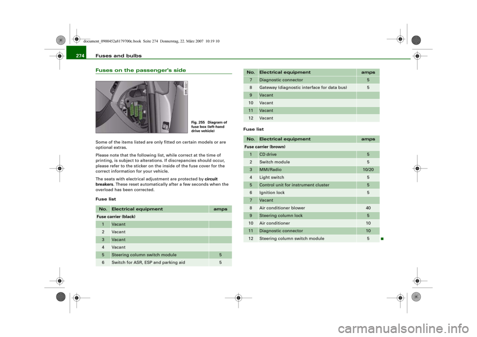
Fig. 255 Diagram of
fuse box (left-hand
drive vehicle)
7
Diagnostic connector
5
8
Gateway (diagnostic interface for data bus)
5
9
Vacant
10
Vacant
11
Vacant
12
Vacant
No.
Electrical equipment
amps
Fuse carrier (brown)1
CD drive
5
2
Switch module
5
3
MMI/Radio
10/20
4
Light switch
5
5
Control unit for instrument cluster
5
6
Ignition lock
5
7
Vacant
8
Air conditioner blower
40
9
Steering column lock
5
10
Air conditioner
10
11
Diagnostic connector
10
12
Steering column switch module
5
No.
Electrical equipment
amps
document_0900452a8179700c.book Seite 274 Donnerstag, 22. März 2007 10:19 10
Page 277 of 313

Fuses and bulbs275
Controls
Safety
Driving tips
General maintenance
Self-help
Technical data
Fuse list for luggage compartment– Remove the trim.
– Open the fuse cover.Fuse listFuse list
Fuse listNo.
Electrical equipment
amps
Fuse carrier (black)
1
Vacant
2
Control unit for trailer
15
3
Control unit for trailer
20
4
Control unit for trailer
20
5
Electronic parking brake
5
6
Electronic suspension control
15
7
Electronic parking brake
30
8
Control unit 2 for vehicle's electrical system
30
9
Vacant
Fig. 256 Diagram of
fuse panel
10
Control unit 2 for vehicle's electrical system
30
11
Control unit 2 for vehicle's electrical system
20
12
Vacant
No.
Electrical equipment
amps
Fuse carrier (brown)
1
Electrical socket
15
2
Vacant
3
Radio/navigation
7.5
4
Control unit for digital sound system
30
5
MMI
5
6
Door control unit (driver's side)
30
7
Electronic parking brake
30
8
Seat heating, rear
30
9
Electric window (right)
30
10
Remote control receiver for auxiliary heating
5
11
Door control unit (passenger side)
15
12
Control unit for reversing camera
5
No.
Electrical equipment
amps
Fuse carrier (red)
1
Socket, centre console, rear
15
2
Socket, centre console, front
15
3
Socket, luggage compartment
15
No.
Electrical equipment
amps
document_0900452a8179700c.book Seite 275 Donnerstag, 22. März 2007 10:19 10
Page 280 of 313

Fuses and bulbs 278Bulb holders with a bayonet fastenerIn the case of bulb holders with a bayonet fastener please
proceed as follows:
Removing the bulb holder
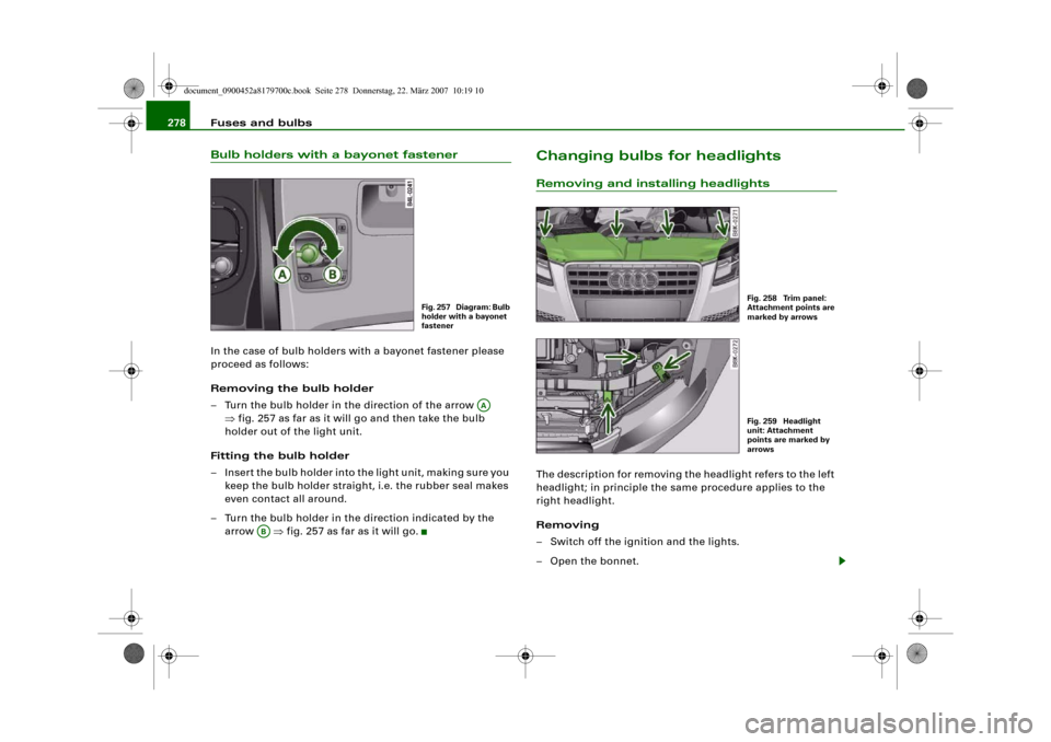
– Turn the bulb holder in the direction of the arrow
⇒fig. 257 as far as it will go and then take the bulb
holder out of the light unit.
Fitting the bulb holder
– Insert the bulb holder into the light unit, making sure you
keep the bulb holder straight, i.e. the rubber seal makes
even contact all around.
– Turn the bulb holder in the direction indicated by the
arrow ⇒fig. 257 as far as it will go.
Changing bulbs for headlightsRemoving and installing headlightsThe description for removing the headlight refers to the left
headlight; in principle the same procedure applies to the
right headlight.
Removing
– Switch off the ignition and the lights.
– Open the bonnet.
Fig. 257 Diagram: Bulb
holder with a bayonet
fastener
AA
AB
Fig. 258 Trim panel:
Attachment points are
marked by arrowsFig. 259 Headlight
unit: Attachment
points are marked by
arrows
document_0900452a8179700c.book Seite 278 Donnerstag, 22. März 2007 10:19 10