2008 AUDI A4 maintenance
[x] Cancel search: maintenancePage 229 of 342
Intelligent technology227
Controls
Safety
Driving tips
General maintenance
Self-help
Technical data current even when the ignition is off. In some cases there may not
be enough power available to start the engine.
Your vehicle is equipped with an intelligent power management
system to control the distribution of electrical energy. This signifi-
cantly improves reliability when starting the engine, and also
prolongs the life of the battery.
The main functions incorporated in the power management system
are battery diagnosis, residual current management and dynamic
power management.
Battery diagnosis
The battery diagnosis function constantly registers the condition of
the battery. Sensors detect the battery voltage, battery current and
battery temperature. This enables the system to calculate the
current power level and charge condition of the battery.
Residual current management
The residual current management reduces power consumption
while the vehicle is parked. It controls the supply of power to the
various electrical components while the ignition is switched off. The
system takes the battery diagnosis data into consideration.
Depending on the power level of the battery, the individual electrical
components are switched off one after the other to prevent the
battery from losing too much charge and to ensure that the engine
can be started reliably.
Dynamic power management
While the vehicle is moving, this function distributes the available
power to the various electrical components and systems according
to their requirements. The power management ensures that on-
board systems do not consume more electrical power than the
alternator can supply, and thus maintains the maximum possible
battery power level.
Note
•
The power management system is not able to overcome the
given physical limits. Please remember that the power and life of
the battery are limited.
•
A warning message will appear ⇒page 228, “Driver message in
the instrument cluster display” if the battery power has dropped to
a level where reliable starting is impaired.
Points to remember
Starting ability has first priority.Short trips, city traffic and low temperatures all place a heavy load
on the battery. In these conditions a large amount of power is
consumed, but only a small amount is supplied. The situation is also
critical if electrical equipment is in use when the engine is not
running. In this case power is consumed when none is being gener-
ated.
In these situations you will be aware that the power management
system is intervening to control the distribution of electrical power.
When the vehicle is parked for long periods
If you do not drive your vehicle for a period of several days or weeks,
the power management will gradually shut off the on-board
systems one by one, or reduce the amount of current they are using.
This limits the amount of power consumed and helps to ensure reli-
able starting even after a long period.
Please note that certain convenience features, such as the Audi
advanced key*, the remote control key or the electrical seat adjust-
ment may not be available when you unlock the vehicle. These func-
tions will be restored when you switch on the ignition and start the
engine.
document_0900452a81b1b9de.book Seite 227 Donnerstag, 26. Juli 2007 9:16 09
Page 231 of 342
Your vehicle and the environment229
Controls
Safety
Driving tips
General maintenance
Self-help
Technical data
Your vehicle and the environmentRunning inA new vehicle should be run in over a distance of 1,500 km. For the
first 1,000 km the engine speed should not exceed 2/3 of the
maximum permissible engine speed – do not use full throttle and do
not tow a trailer or caravan. From 1,000 to 1,500 km you can gradu-
ally increase the engine rpm and road speed.
During its first few hours of running, the internal friction in the
engine is greater than later on when all the moving parts have
bedded down.
How the vehicle is driven for the first 1,500 km also influences the
engine quality. After the first 1,500 km you should continue driving
at moderate engine speeds, in particular when the engine is cold.
This helps to reduce wear and tear on the engine and increases the
potential mileage which can be covered by the engine.
You should also avoid driving with the engine speed too low.
Change down to a lower gear when the engine no longer runs
“smoothly”. Excessively high engine speeds are prevented by an
automatic rev limiter.Emission control systemsCatalytic converter
Applies to vehicles with petrol engine: The vehicle must only be
used with unleaded petrol, otherwise the catalytic converter will be
destroyed.
Never run the tank completely dry. The irregular fuel supply can
cause misfiring, which would allow unburnt fuel to enter the
exhaust system, which could cause overheating and damage the
catalytic converter.Diesel particulate filter
Applies to vehicles with diesel engine: The diesel particulate filter
can filter out almost all soot particles contained in the exhaust gas.
In normal driving conditions the filter is self-cleaning. Should the
self-cleaning function of the filter not be able to operate, e.g. when
the vehicle is continuously used only for short trips, the filter
becomes obstructed with soot and the symbol
for the diesel
particulate filter lights up ⇒page 38.
WARNING
•
Because of the high temperatures which can occur in the emis-
sion control system (catalytic converter or diesel particulate
filter), do not park the vehicle where the exhaust can come into
contact with flammable materials under the car (e.g. on grass or
at the forest edge). - Fire hazard!
•
Do not apply any underseal agents in the area around the
exhaust system - fire hazard!
How to improve economy and minimise pollutionFuel economy, environmental impact and wear on the engine,
brakes and tyres depend largely on the way you drive the vehicle. By
adopting an economical driving style and anticipating the traffic
situation ahead, you can reduce fuel consumption by 10-15%. The
following section gives you some tips on lessening the impact on
the environment and reducing your operating costs at the same
time.
document_0900452a81b1b9de.book Seite 229 Donnerstag, 26. Juli 2007 9:16 09
Page 233 of 342
Your vehicle and the environment231
Controls
Safety
Driving tips
General maintenance
Self-help
Technical data Save electrical energy
The engine drives the alternator to generate electricity. This means
that fuel consumption rises when more power is required for elec-
trical equipment. Switch off electrical equipment when it is not
needed. Electrical equipment which uses a lot of electricity includes
the blower (at a high setting), the rear window heating and the seat
heating*.
Environmental compatibilityEnvironmental protection is a top priority in the design, choice of
materials and production of your new Audi.
Design measures for economical recycling•
Joints and connections designed for ease of dismantling
•
Modular construction to facilitate dismantling
•
Increased use of single-grade materials
•
Plastic parts and elastomers are labelled in accordance with ISO
1043, ISO 11469 and ISO 1629
Choice of materials
•
Nearly all materials used can be recycled
•
Similar types of plastics grouped together for easy recycling
•
Recycled materials used in manufacture
•
Reduced vapour emissions from plastics
•
CFC-free refrigerant in air conditioner
Compliance with the laws prohibiting the use of: Cadmium,
asbestos, lead, mercury and chrome VI.
Manufacturing methods
•
Using recycling material for manufacturing plastic parts
•
Solvent-free cavity sealing
•
Solvent-free wax for protecting the vehicles in transit
•
Solvent-free adhesives
•
No CFCs used in production
•
Surplus materials used extensively for energy conversion and
building materials
•
Overall water consumption reduced
•
Heat recovery systems
•
Water-soluble paint
document_0900452a81b1b9de.book Seite 231 Donnerstag, 26. Juli 2007 9:16 09
Page 235 of 342
Towing a trailer233
Controls
Safety
Driving tips
General maintenance
Self-help
Technical data additional mirrors fitted. Both exterior mirrors should be mounted
on hinged extension brackets. Adjust the mirrors to give sufficient
vision to the rear.
Headlights
Before starting a journey, check the headlight beam settings with
the trailer hitched up. If necessary, alter the height of the headlight
beams by means of the headlight range control ⇒page 60.
Power supply
When you remove the ignition key the power supply to the trailer is
interrupted.
Removable ball joint coupling
Vehicles with a factory-fitted towing bracket are equipped with a
removable ball joint coupling. It is carried under the floor panel on
the left-hand side of the luggage compartment and is secured by a
strap.
Note
We recommend having the car serviced between the normal inspec-
tion intervals if it used frequently for towing a trailer.Applies to vehicles: with towing bracketTrailer stabilisation system
Trailer stabilisation helps to reduce the risk of the vehicle
skidding when towing a trailer.The trailer stabilisation system is operational only when the ESP is
switched on and there is no malfunction in the ESP ⇒page 17.
When is the trailer stabilisation system activated?
Trailer stabilisation is active when the following requirements are
met:•
The ESP must NOT be switched off ⇒page 222,
•
The trailer connector must be properly secured in the vehicle
socket.
•
Vehicle speed must be higher than approx. 60 km/h.
How trailer stabilisation works:
In many cases, the driver can stabilise a swaying trailer by manually
braking the vehicle.
However, if the ESP detects that the trailer is swaying and this is
affecting the towing vehicle, it will automatically brake the vehicle
to stabilise the trailer by slowing it down. The warning lamp
will
light up in the instrument cluster. If possible, do not turn the
steering wheel at this stage.
In order to warn traffic behind you, the brake lights will come on
during this automatic braking operation.
A trailer weighing less than 70% of the kerb weight of the towing
vehicle may sway quite considerably without the trailer stabilisation
system intervening. This can happen when the swaying movements
of the light-weight trailer are not or hardly passed on to the towing
vehicle and are therefore not detected by the ESP.
If the system for activating the trailer brake lights is defective, this
will be indicated in the instrument cluster display ⇒page 37, “Bulb
monitor ”.
Requirements for correct functioning of the trailer
stabilisation system
If these conditions are not met in full, the trailer stabilisation system
will only intervene to a limited extent or not at all ⇒.
•
The electrical connection between the towing vehicle and the
trailer must be functioning correctly, without any defects.
•
The load on the trailer must be properly secured.
•
The tyre pressures on both the vehicle and the trailer must be
adapted to the load that is being carried.
•
Where possible, operate the trailer with the maximum permitted
draw bar weight.
document_0900452a81b1b9de.book Seite 233 Donnerstag, 26. Juli 2007 9:16 09
Page 237 of 342
Towing a trailer235
Controls
Safety
Driving tips
General maintenance
Self-help
Technical data
Applies to vehicles: with towing bracketAccessories
Before mounting equipment and accessories (e.g. bicycle
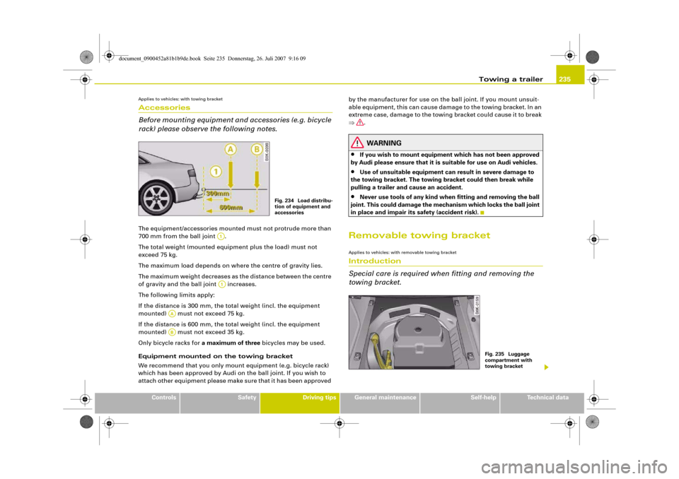
rack) please observe the following notes.The equipment/accessories mounted must not protrude more than
700 mm from the ball joint .
The total weight (mounted equipment plus the load) must not
exceed 75 kg.
The maximum load depends on where the centre of gravity lies.
The maximum weight decreases as the distance between the centre
of gravity and the ball joint increases.
The following limits apply:
If the distance is 300 mm, the total weight (incl. the equipment
mounted) must not exceed 75 kg.
If the distance is 600 mm, the total weight (incl. the equipment
mounted) must not exceed 35 kg.
Only bicycle racks for a maximum of three bicycles may be used.
Equipment mounted on the towing bracket
We recommend that you only mount equipment (e.g. bicycle rack)
which has been approved by Audi on the ball joint. If you wish to
attach other equipment please make sure that it has been approved by the manufacturer for use on the ball joint. If you mount unsuit-
able equipment, this can cause damage to the towing bracket. In an
extreme case, damage to the towing bracket could cause it to break
⇒.
WARNING
•
If you wish to mount equipment which has not been approved
by Audi please ensure that it is suitable for use on Audi vehicles.
•
Use of unsuitable equipment can result in severe damage to
the towing bracket. The towing bracket could then break while
pulling a trailer and cause an accident.
•
Never use tools of any kind when fitting and removing the ball
joint. This could damage the mechanism which locks the ball joint
in place and impair its safety (accident risk).
Removable towing bracketApplies to vehicles: with removable towing bracketIntroduction
Special care is required when fitting and removing the
towing bracket.
Fig. 234 Load distribu-
tion of equipment and
accessories
A1A1
AAAB
Fig. 235 Luggage
compartment with
towing bracket
document_0900452a81b1b9de.book Seite 235 Donnerstag, 26. Juli 2007 9:16 09
Page 239 of 342
Towing a trailer237
Controls
Safety
Driving tips
General maintenance
Self-help
Technical data
– Also check the shaft section of the ball joint and its asso-
ciated mechanical parts to make sure they are clean and
undamaged.Continued ⇒page 237, “Fitting the ball joint (step 2)”.
WARNING
It is important to keep the mounting fixture clean. Otherwise the
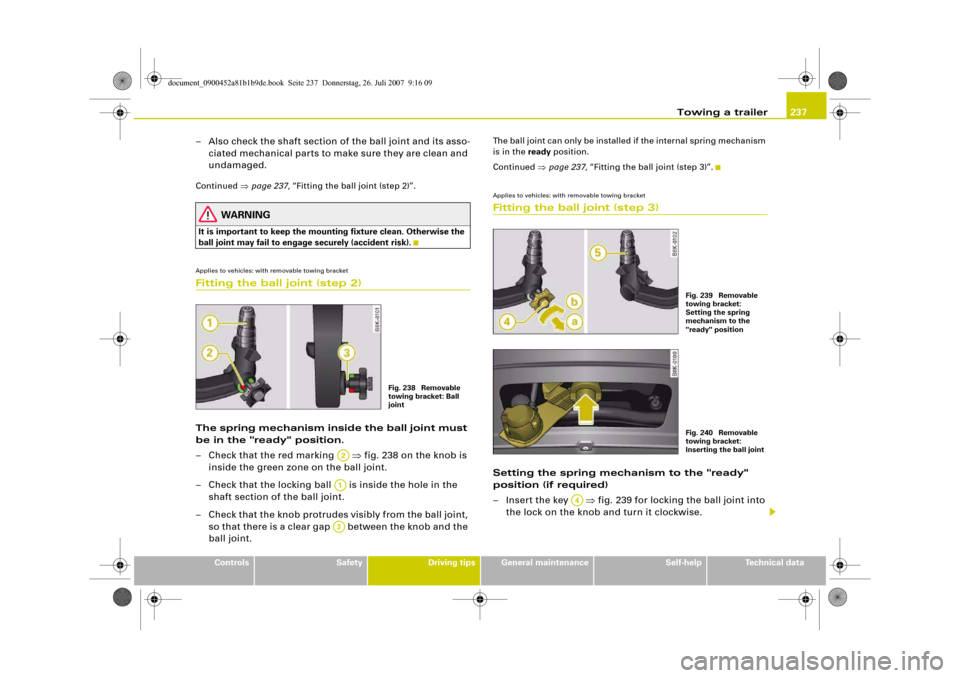
ball joint may fail to engage securely (accident risk).Applies to vehicles: with removable towing bracketFitting the ball joint (step 2)The spring mechanism inside the ball joint must
be in the "ready" position.
– Check that the red marking ⇒fig. 238 on the knob is
inside the green zone on the ball joint.
– Check that the locking ball is inside the hole in the
shaft section of the ball joint.
– Check that the knob protrudes visibly from the ball joint,
so that there is a clear gap between the knob and the
ball joint.
The ball joint can only be installed if the internal spring mechanism
is in the ready position.
Continued ⇒page 237, “Fitting the ball joint (step 3)”.Applies to vehicles: with removable towing bracketFitting the ball joint (step 3)Setting the spring mechanism to the "ready"
position (if required)
– Insert the key ⇒fig. 239 for locking the ball joint into
the lock on the knob and turn it clockwise.
Fig. 238 Removable
towing bracket: Ball
joint
A2A1A3
Fig. 239 Removable
towing bracket:
Setting the spring
mechanism to the
"ready" positionFig. 240 Removable
towing bracket:
Inserting the ball joint
A4
document_0900452a81b1b9de.book Seite 237 Donnerstag, 26. Juli 2007 9:16 09
Page 241 of 342
Towing a trailer239
Controls
Safety
Driving tips
General maintenance
Self-help
Technical data
– Check that the ball joint fits tightly in the mounting
fixture (try moving it about to check).
Electrical socket for trailer
– The cable of the towing bracket can be connected to the
socket ⇒page 238, fig. 242.If the safety check is not satisfactory, the ball joint must be fitted
again properly.
WARNING
To avoid accidents, the ball joint must meet all the safety require-
ments listed in the safety check. The towing bracket must not be
used if any one of these requirements is not met. If this is the case,
you should contact a qualified workshop.Applies to vehicles: with removable towing bracketRemoving the ball joint
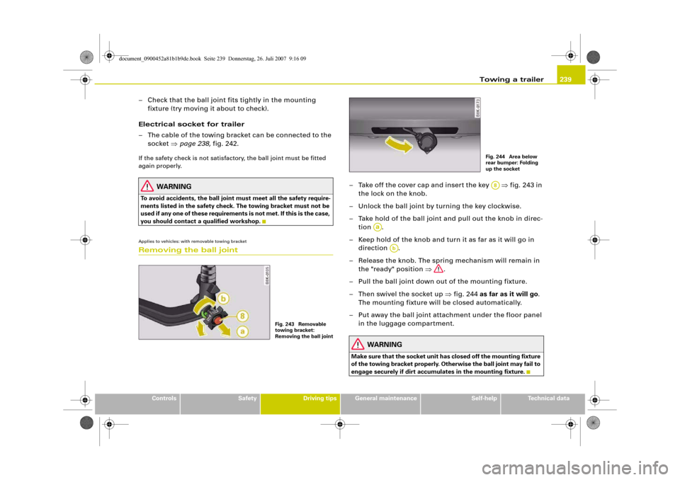
– Take off the cover cap and insert the key ⇒fig. 243 in
the lock on the knob.
– Unlock the ball joint by turning the key clockwise.
– Take hold of the ball joint and pull out the knob in direc-
tion .
– Keep hold of the knob and turn it as far as it will go in
direction .
– Release the knob. The spring mechanism will remain in
the "ready" position ⇒.
– Pull the ball joint down out of the mounting fixture.
– Then swivel the socket up ⇒fig. 244 as far as it will go.
The mounting fixture will be closed automatically.
– Put away the ball joint attachment under the floor panel
in the luggage compartment.
WARNING
Make sure that the socket unit has closed off the mounting fixture
of the towing bracket properly. Otherwise the ball joint may fail to
engage securely if dirt accumulates in the mounting fixture.
Fig. 243 Removable
towing bracket:
Removing the ball joint
Fig. 244 Area below
rear bumper: Folding
up the socketA8
Aa
Ab
document_0900452a81b1b9de.book Seite 239 Donnerstag, 26. Juli 2007 9:16 09
Page 243 of 342
Towing a trailer241
Controls
Safety
Driving tips
General maintenance
Self-help
Technical data
document_0900452a81b1b9de.book Seite 241 Donnerstag, 26. Juli 2007 9:16 09