2008 AUDI A4 rear lever
[x] Cancel search: rear leverPage 39 of 342
Driver information system37
Controls
Safety
Driving tips
General maintenance
Self-help
Technical data
Light sensor / rain sensor defective
Automatic headlights / automatic wipers defective
If the symbol appears, this means that the light sensor / rain
sensor is not functioning.For safety reasons, the dipped beam head-
lights will then be switched on permanently when the light switch
is set to the AUTO position. However, you can still switch the lights
on and off in the normal way with the light switch. If the rain sensor
is defective, the functions operated via the windscreen wiper lever
will still be available. You should have the light sensor / rain sensor
checked by a qualified workshop as soon as possible.
Brake pads worn
Brake pads!
If the symbol lights up, have the front brake pads (and, for
safety's sake the rear pads as well) inspected by a qualified
workshop.
Applies to vehicles: with bulb monitorBulb monitor
The bulb monitor checks whether the lights on the vehicle
are working.The bulb monitor checks whether the lights on the vehicle are
working. If it detects a defective bulb on the vehicle it will show a
yellow warning symbol together with a message indicating which
light is not working.
Bulb failure
If the symbol
lights up, this means that one of the turn signals
(front or rear), headlights, brake lights, rear lights, fog lights or the
rear fog light is not working.
WARNING
•
Bulbs are sensitive to pressure. The glass can break when you
touch the bulb, causing injury.
•
Incorrect handling of the high-voltage element of xenon gas-
discharge bulbs* can have potentially fatal consequences.Note
Have the components repaired or replaced by a qualified
workshop.Applies to vehicles: with washer fluid warning systemWasher fluid level low
Please top up washer fluid
If the symbol lights up, top up the fluid for the windscreen
washer and headlight washer system* ⇒page 267.
Fuel level low
Please refuel
When this symbol
comes on for the first time, there are about
8 litres of fuel left in the tank. You should fill up as soon as possible
⇒page 252.
If this warning symbol lights up although the fuel tank is sufficiently
filled, there is a malfunction in the fuel tank system. The display will
also show the driver message Tank system malfunction ! Contact
workshop. Please contact a qualified workshop.
document_0900452a81b1b9de.book Seite 37 Donnerstag, 26. Juli 2007 9:16 09
Page 64 of 342
Lights and vision 62•
When reaching the tail end of a traffic jam
•
If your vehicle breaks down or there is an emergency
•
If your vehicle is being towed away, or if you are towing another
vehicle.
Turn signal and main beam lever
The turn signal and main beam lever also operates the
parking lights and the headlight flasher.The turn signal and main beam headlight lever has the
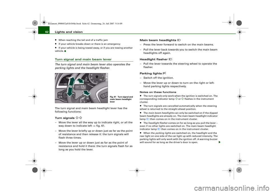
following functions:
Turn signals
– Move the lever all the way up to indicate right, or all the
way down to indicate left ⇒fig. 61.
– Move the lever briefly up or down just as far as the point
of resistance and then release it: the turn signals will
flash three times.
– Move the lever up or down just as far as the point of
resistance and hold it there: the turn signals flash for as
long as you hold the lever.Main beam headlights
– Press the lever forward to switch on the main beams.
– Pull the lever back towards you to switch the main beam
headlights off again.
Headlight flasher
– Pull the lever towards the steering wheel to operate the
flasher.
Parking lights
– Switch off the ignition.
– Move the lever up or down to turn on the right or left-
hand parking lights respectively.Notes on these functions•
The turn signals only work when the ignition is switched on. The
corresponding indicator lamp
or
flashes in the instrument
cluster.
•
The turn signals are cancelled automatically when the steering
wheel is returned to the straight-ahead position.
•
The main beam headlights can only be switched on if the dipped
beam headlights are already on. The main beam headlight indicator
lamp then comes on in the instrument cluster.
•
The headlight flasher comes on for as long as you pull the lever –
even if no other lights are switched on. The main beam headlight
indicator lamp
then comes on in the instrument cluster.
•
When the parking lights are switched on, the headlight and the
rear light on one side of the car light up with reduced intensity. The
parking lights will only work with the ignition off. A warning buzzer
will sound for as long as the driver's door is open.
Fig. 61 Turn signal and
main beam headlight
lever
document_0900452a81b1b9de.book Seite 62 Donnerstag, 26. Juli 2007 9:16 09
Page 67 of 342
Lights and vision65
Controls
Safety
Driving tips
General maintenance
Self-help
Technical data
– To retract the sun blind automatically when reversing,
select: Function selector button > Windows >
Automatic rear blind > on.If you switch the Automatic rear blind function on in the sound
system or MMI*, the raised sun blind will be retracted automatically
when reverse gear is engaged ⇒page 55. In this way, the rear blind
will not obstruct your vision when reversing. The rear blind returns
to its raised position when reverse gear is disengaged and the
vehicle is driven forwards at a speed above about 15 km/h. The
current setting is automatically stored and assigned to the remote
control key.
If the rear blind was rolled in automatically when reversing and then
the ignition was switched off and on again, the blind will not roll
back out again when you select a forward gear and the speed
exceeds 15 km/h. You will then have to press the button
on the
centre console to extend the blind again.
The sun blind for the rear window switches off automatically when
it reaches the end position. It can be made to move in the other
direction before it reaches its end position by briefly pressing the
switch a second time. If the ignition is turned off while the blind is
still moving, it continues until it reaches the end position before
switching off.
Note
•
An overload cut-out may be activated if the sun blind is operated
repeatedly. There will then be a short delay before the blind can be
operated again.
•
As the material of the sun blind is less flexible at low tempera-
tures the electric actuator is switched off when the temperature in
the car is below -5°C. The blind can only be operated when the
temperature in the car's interior rises above this level.
Windscreen wipersWindscreen wipers
The windscreen wiper lever controls the windscreen
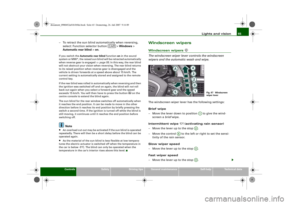
wipers and the automatic wash and wipe.The windscreen wiper lever has the following settings:
Brief wipe
– Move the lever down to position to give the wind-
screen a brief wipe.
Intermittent wipe
(activating rain sensor)
– Move the lever up to the stop .
– Move the control to the left or right to set the sensi-
tivity of the rain sensor.
Slow wiper speed
– Move the lever up to the stop .
Fast wiper speed
– Move the lever up to the stop .
CAR
Fig. 67 Windscreen
wiper lever
A1
A2
AA
A3A4
document_0900452a81b1b9de.book Seite 65 Donnerstag, 26. Juli 2007 9:16 09
Page 70 of 342
Lights and vision 68when they are in the service position you will also avoid damaging
the paintwork on the bonnet.•
off - the windscreen wipers will be moved back to their original
position.Caution
Never move the vehicle with the front wiper arms in a raised posi-
tion as they are automatically moved back to their normal park posi-
tion above a speed of 6 km/h. The paintwork on the bonnet may be
damaged as a result.
Note
•
You can also use the service position, for example, if you want to
fix a cover over the windscreen in the winter to keep it clear of ice.
•
The service position is automatically set to off when you operate
the windscreen wiper lever or the road speed exceeds 6 km/h.
Changing wiper blades
Good wiper blades are essential for clear vision.Taking off the wiper blade
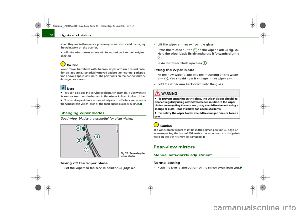
– Set the wipers to the service position ⇒page 67.– Lift the wiper arm away from the glass.
– Press the release button on the wiper blade ⇒fig. 70.
Hold the wiper blade firmly and press it forwards slightly
.
– Slide the wiper blade upwards .
Fitting the wiper blade
– Fit the new wiper blade into the mounting on the wiper
arm . You should hear it engage in the wiper arm.
– Fold the wiper arm back down onto the glass.
WARNING
•
To prevent smearing on the glass, the wiper blades should be
cleaned regularly using a window cleaner solution. If the wiper
blades are very dirty (insects etc.), they should be cleaned using a
sponge or cloth – bad visibility can cause accidents.
•
For safety, the wiper blades should be changed once or twice a
year.Caution
The windscreen wipers must be in the service position ⇒page 67
when replacing the blades! Otherwise the wiper motor or the paint-
work on the bonnet may be damaged.Rear-view mirrorsManual anti-dazzle adjustmentNormal setting
– Push the lever at the bottom of the mirror away from you.
Fig. 70 Removing the
wiper blades
A1
A2
A3
A4
document_0900452a81b1b9de.book Seite 68 Donnerstag, 26. Juli 2007 9:16 09
Page 71 of 342
Lights and vision69
Controls
Safety
Driving tips
General maintenance
Self-help
Technical data
Anti-dazzle setting
– Pull the lever at the bottom of the mirror towards you.Applies to vehicles: with automatic anti-dazzle adjustment for interior mirrorAutomatic anti-dazzle adjustment
The automatic anti-dazzle function can be switched on
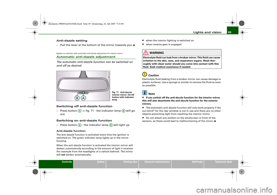
and off as desired.Switching off anti-dazzle function
– Press button ⇒fig. 71 - the indicator lamp will go
out.
Switching on anti-dazzle function
– Press button - the indicator lamp will light up.Anti-dazzle function
The anti-dazzle function is activated every time the ignition is
switched on. The green indicator lamp lights up in the mirror
housing.
When the anti-dazzle function is activated the interior mirror will
darken automatically according to the amount of light it receives
(for example from the headlights of a vehicle behind). The mirror
will not darken automatically:
•
when the interior lighting is switched on
•
when reverse gear is engaged
WARNING
Electrolyte fluid can leak from a broken mirror. This fluid can cause
irritation to the skin, eyes, and respiratory organs. Wash thor-
oughly with clean water should you come into contact with this
fluid. Seek medical assistance if needed.
Caution
Electrolyte fluid leaking from a broken mirror can cause damage to
plastic surfaces. Use a sponge or similar to remove the fluid as soon
as possible.
Note
•
If you switch off the anti-dazzle function for the interior mirror,
this will also deactivate the anti-dazzle function for the exterior
mirrors.
•
The automatic anti-dazzle function will only work properly if the
sun blind* for the rear window is not in use and there are no other
objects preventing light from reaching the interior mirror.
•
Do not attach any stickers to the windscreen in front of the
sensors, as these could lead to malfunctioning of the mirror.
Fig. 71 Anti-dazzle
interior mirror: On/off
button with indicator
lamp
AA
AB
AA
AB
document_0900452a81b1b9de.book Seite 69 Donnerstag, 26. Juli 2007 9:16 09
Page 75 of 342
Seats and storage73
Controls
Safety
Driving tips
General maintenance
Self-help
Technical data
Seats and storageManual adjustment of front seatsApplies to vehicles: with manual seat adjustmentSeat adjuster controls
There are several seat adjustment functions for your
comfort and convenienceSome of the controls shown are only fitted on certain models or are
optional extras.
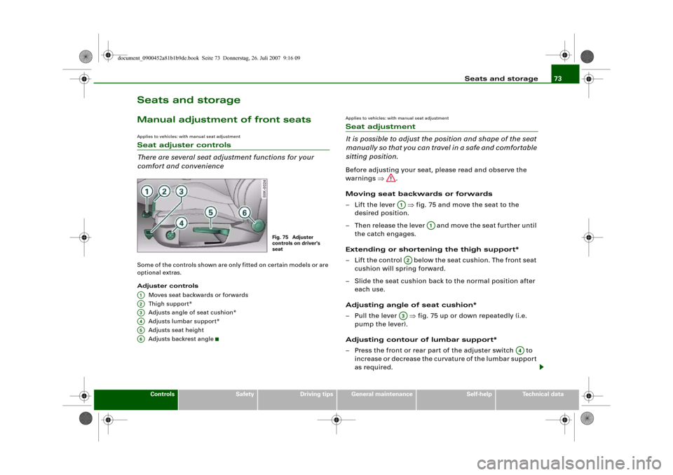
Adjuster controls
Moves seat backwards or forwards
Thigh suppor t*
Adjusts angle of seat cushion*
Adjusts lumbar support*
Adjusts seat height
Adjusts backrest angle
Applies to vehicles: with manual seat adjustmentSeat adjustment
It is possible to adjust the position and shape of the seat
manually so that you can travel in a safe and comfortable
sitting position.Before adjusting your seat, please read and observe the
warnings ⇒.
Moving seat backwards or forwards
– Lift the lever ⇒fig. 75 and move the seat to the
desired position.
– Then release the lever and move the seat further until
the catch engages.
Extending or shortening the thigh support*
– Lift the control below the seat cushion. The front seat
cushion will spring forward.
– Slide the seat cushion back to the normal position after
each use.
Adjusting angle of seat cushion*
– Pull the lever ⇒fig. 75 up or down repeatedly (i.e.
pump the lever).
Adjusting contour of lumbar support*
– Press the front or rear part of the adjuster switch to
increase or decrease the curvature of the lumbar support
as required.
Fig. 75 Adjuster
controls on driver's
seat
A1A2A3A4A5A6
A1
A1
A2A3
A4
document_0900452a81b1b9de.book Seite 73 Donnerstag, 26. Juli 2007 9:16 09
Page 83 of 342
Seats and storage81
Controls
Safety
Driving tips
General maintenance
Self-help
Technical data
– To open the storage compartment, pull the handle
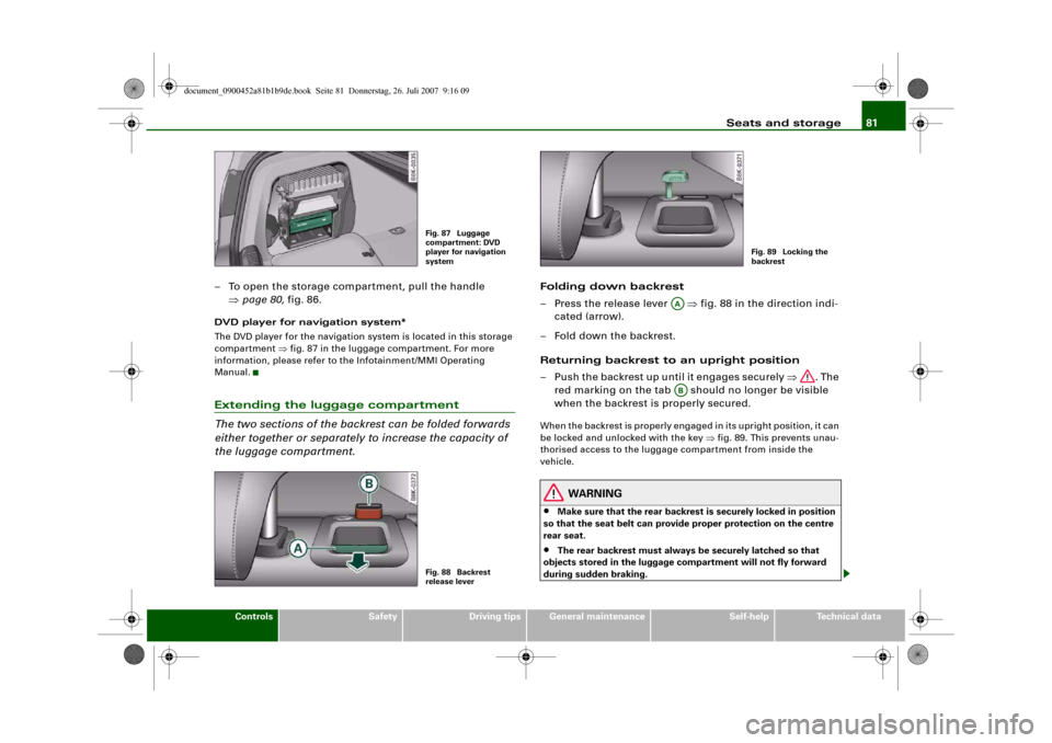
⇒page 80, fig. 86.DVD player for navigation system*
The DVD player for the navigation system is located in this storage
compartment ⇒fig. 87 in the luggage compartment. For more
information, please refer to the Infotainment/MMI Operating
Manual.Extending the luggage compartment
The two sections of the backrest can be folded forwards
either together or separately to increase the capacity of
the luggage compartment.
Folding down backrest
– Press the release lever ⇒fig. 88 in the direction indi-
cated (arrow).
– Fold down the backrest.
Returning backrest to an upright position
– Push the backrest up until it engages securely ⇒. The
red marking on the tab should no longer be visible
when the backrest is properly secured.When the backrest is properly engaged in its upright position, it can
be locked and unlocked with the key ⇒fig. 89. This prevents unau-
thorised access to the luggage compartment from inside the
vehicle.
WARNING
•
Make sure that the rear backrest is securely locked in position
so that the seat belt can provide proper protection on the centre
rear seat.
•
The rear backrest must always be securely latched so that
objects stored in the luggage compartment will not fly forward
during sudden braking.
Fig. 87 Luggage
compartment: DVD
player for navigation
systemFig. 88 Backrest
release lever
Fig. 89 Locking the
backrest
AAAB
document_0900452a81b1b9de.book Seite 81 Donnerstag, 26. Juli 2007 9:16 09
Page 299 of 342
Self-help297
Controls
Safety
Driving tips
General maintenance
Self-help
Technical data
Rear towline anchorage
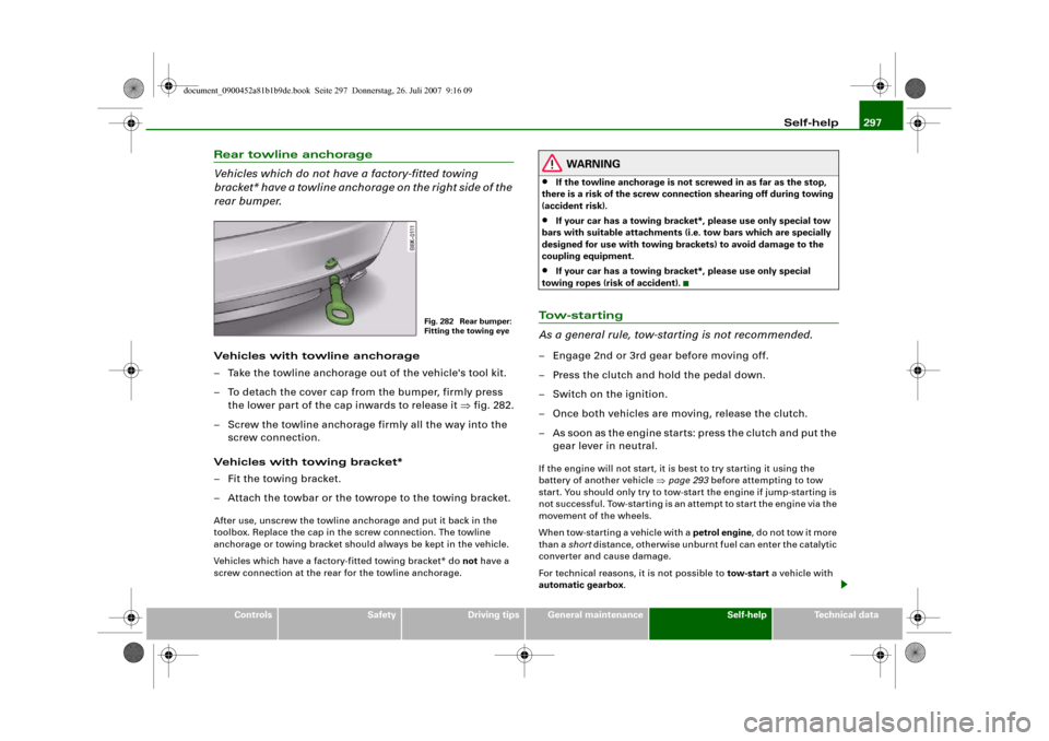
Vehicles which do not have a factory-fitted towing
bracket* have a towline anchorage on the right side of the
rear bumper.Vehicles with towline anchorage
– Take the towline anchorage out of the vehicle's tool kit.
– To detach the cover cap from the bumper, firmly press
the lower part of the cap inwards to release it ⇒fig. 282.
– Screw the towline anchorage firmly all the way into the
screw connection.
Vehicles with towing bracket*
– Fit the towing bracket.
– Attach the towbar or the towrope to the towing bracket.After use, unscrew the towline anchorage and put it back in the
toolbox. Replace the cap in the screw connection. The towline
anchorage or towing bracket should always be kept in the vehicle.
Vehicles which have a factory-fitted towing bracket* do not have a
screw connection at the rear for the towline anchorage.
WARNING
•
If the towline anchorage is not screwed in as far as the stop,
there is a risk of the screw connection shearing off during towing
(accident risk).
•
If your car has a towing bracket*, please use only special tow
bars with suitable attachments (i.e. tow bars which are specially
designed for use with towing brackets) to avoid damage to the
coupling equipment.
•
If your car has a towing bracket*, please use only special
towing ropes (risk of accident).
To w - s t a r t i n g
As a general rule, tow-starting is not recommended.– Engage 2nd or 3rd gear before moving off.
– Press the clutch and hold the pedal down.
– Switch on the ignition.
– Once both vehicles are moving, release the clutch.
– As soon as the engine starts: press the clutch and put the
gear lever in neutral.If the engine will not start, it is best to try starting it using the
battery of another vehicle ⇒page 293 before attempting to tow
start. You should only try to tow-start the engine if jump-starting is
not successful. Tow-starting is an attempt to start the engine via the
movement of the wheels.
When tow-starting a vehicle with a petrol engine, do not tow it more
than a short distance, otherwise unburnt fuel can enter the catalytic
converter and cause damage.
For technical reasons, it is not possible to tow-start a vehicle with
automatic gearbox.
Fig. 282 Rear bumper:
Fitting the towing eye
document_0900452a81b1b9de.book Seite 297 Donnerstag, 26. Juli 2007 9:16 09