Page 265 of 291

RIGHT HAND DRIVE VERSION
263
MILEAGE RECORDER
Odometer display with double counter for
showing the total and trip meter in miles
and showing the headlamp aiming.
The display shows:
– the miles travelled on the first line (6
digits)
– the trip meter in miles on the second
line (4 digits)
– at the side the position of the headlamp
aiming device.
fig. 5
A0A0304m
To reset the trip meter in miles, keep but-
ton (A-fig. 5) on the panel at the side of
the steering column pressed for a few mo-
ments.
IMPORTANTIf the battery is discon-
nected the distance of the trip meter is not
stored.STEERING WHEEL
ADJUSTMENTS
The driver can adjust the steering wheel
position in rake and height.
To do this, release the lever (A-fig. 6)
pulling it towards the steering wheel.
After moving the steering wheel to the
most suitable position, lock it pushing the
lever fully forwards.
fig. 6
A0A0307m
Any adjustment of the
steering wheel position
must be carried out only with the
vehicle stationary.
WARNING
Page 266 of 291

RIGHT HAND DRIVE VERSION
264
Driver’s side (fig. 8)
The driver’s door panel contains the but-
tons that control the following windows,
with the ignition key at MAR:
A- left window
B- right window.
Press the button to lower the window. Pull
to raise it.
IMPORTANTThe driver’s power window
is fitted with the “continuous automatic op-
eration” device for both lowering and raising
the window. A brief press on the upper or
lower part of the button will cause it to move
and continue automatically: the window
stops in the required position by pressing ei-
ther the upper or lower part of the button
again.
fig. 8
A0A0309m
WING MIRROR
ADJUSTMENT
Electric adjustment (fig. 7)
– use the switch (A) to select the mirror
required (right or left);
– pressing the button (B), in one of the
four directions, move the mirror selected pre-
viously;
– Position the switch (A) in the interme-
diate locking position.
IMPORTANTAdjustment is possible on-
ly with the ignition key at MAR.
fig. 7
A0A0308m
POWER WINDOWS
For some versions, the power windows are
fitted with a safety system with crush-pre-
vention seals. The electronic control unit that
operates the system is capable of detect-
ing the presence of an obstacle during the
window closing motion through the special
seals. Should this occur, the system stops
the movement of the window and reverses
it immediately.
IMPORTANTIf the crush-prevention
function is operated for 3 times in 1 minute,
the system automatically sets to the recov-
ery mode (self-protection). To reset the cor-
rect system operating logic, use the control
button. The window will rise in predefined
steps until closing completely. The logic is re-
set and if there are no faults, the window
winder automatically resumes normal oper-
ation; if not, contact Alfa Romeo Authorised
Services.
With the ignition key at STOPor removed,
the power windows remain activated for
about 3 minutes and are deactivated im-
mediately the moment a door is opened.
Page 267 of 291

RIGHT HAND DRIVE VERSION
265
Do not keep the button
pressed when the window
is completely raised or
lowered.
fig. 9
A0A0310m
IMPORTANTIf the car is fitted with
safety seals, after locking the doors, keep-
ing the corresponding button on the remote
control pressed for about 2 seconds the win-
dows and sunroof (if present) are closed au-
tomatically. The remote control button must
be kept pressed until the windows have
completed their stroke, releasing the button
before, the windows stop in the position
they are in at that moment.
On all versions, after unlocking the doors,
keeping the remote control button pressed
for about 2 seconds the windows and sun-
roof (if present) are opened. Passenger’s side (fig. 9)
The button (A) controls the passenger’s
side window.
IMPORTANTThe passenger’s power
window is fitted with the “automatic con-
tinuous operation” device for lowering the
window only. The device works in the same
way as the one on the driver’s side.
Improper use of power
windows can be danger-
ous. Before and during use, always
make sure that the passengers are
not exposed to the risk of harm ei-
ther directly by the moving win-
dows or by personal objects drawn
or knocked by them. When leaving
the car, always remove the igni-
tion key to prevent the power
windows from being operated in-
advertently, and harming anyone
left on board.
WARNING
Page 268 of 291

RIGHT HAND DRIVE VERSION
266
FRONT SEATS
fig. 10
A0A0477m
LENGTHWISE
ADJUSTMENT
(fig. 10)
Raise the lever (A) and push the seat
backwards or forwards; in the driving posi-
tion the arms should be slightly flexed and
the hands should rest on the rim of the steer-
ing wheel.
DRIVER’S SEAT
HEIGHT ADJUSTMENT
(fig. 10)
To raise the seat, pull the lever (B) up-
wards, then work the lever (up and down)
until reaching the required height, then re-
lease it. To lower the seat, push the lever
(B) downwards then work the lever (up and
down) until reaching the required height.
IMPORTANTAdjustment must be car-
ried out only seated in the driver’s seat.
BACK REST ANGLE
ADJUSTMENT
(fig. 10)
Turn the knob (C) until reaching the posi-
tion required.
TILTING THE BACK REST (fig. 10)
(3-door versions)
To gain access to the rear seats, pull the
handle (E), the back rest folds and the seat
is free to run forwards.
A recovery mechanism with memory
makes it possible to take the seat back to
its previous position.
Once the seat back has been returned to
the travelling condition, make sure that it
is correctly clamped, checking that the “red
band” on the upper part of the handle (E)
is concealed. In fact, this “red band” indi-
cates that the seat back is not camped.
Also check that the seat is firmly locked on
the runners, trying to move it to and fro.
DRIVER’S SEAT
LUMBAR ADJUSTMENT
(fig. 10)
Turn the knob (D) until obtaining the most
comfortable position.
Any adjustments are to be
carried out only with the
vehicle stationary.
WARNING
After releasing the adjust-
ment lever, always check
that the seat is locked on the run-
ners, trying to move it to and fro.
The lack of this clamping action
could cause the seat to move un-
expectedly and cause loss of ve-
hicle control.
WARNING
Page 269 of 291

RIGHT HAND DRIVE VERSION
267
FRONT AND SIDE
AIR BAGS
The car is fitted with front Air bags for the
driver (fig. 11), for the passenger (fig. 12)
and side bag (fig. 13) and window bag
(fig. 14).
fig. 11
A0A0311m
fig. 12
A0A0312m
DEACTIVATING THE
PASSENGER’S
FRONT AIR BAG MANUALLY
Should it be absolutely necessary to car-
ry a child on the front seat, the passenger’s
Air bag on the vehicle can be deactivated.
Deactivation takes place using the car ig-
nition key to operate the special switch on
the left hand side of the dashboard
fig. 13
A0A0478m
fig. 14
A0A0479m
(fig. 15). Access to the switch is only pos-
sible with the door open.
The key-operated switch (fig. 15) has
two positions:
1) Passenger’s front Air bag activated:
(ONposition
P) warning light on instru-
ment cluster off; it is absolutely prohibited
to carry a child on the front seat.
2) Passenger’s front Air bag deactivated:
(OFFposition
F) warning light on in-
strument cluster on; it is possible to carry a
child protected by special restraint systems
on the front seat.
The warning light
Fon the cluster stays
on permanently until the passenger’s Air bag
is reactivated.
Deactivation of the passenger’s front Air bag
does not inhibit operation of the side Air bag.
When the door is open, the key can be in-
serted and removed in both positions.
fig. 15
A0A0313m
Page 270 of 291
RIGHT HAND DRIVE VERSION
268
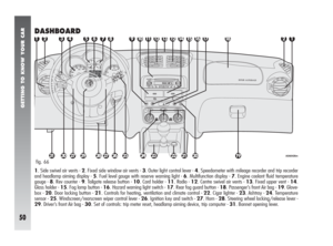
1Upper stationary vent for defrosting or demisting windscreen - 2Upper centre adjustable vent - 3Stationary vents for defrosting or demist-
ing side windows - 4Adjustable centre, swivel vents - 5Side adjustable and swivel outlets - 6Front feet area fixed vents - 7Rear feet area
fixed vents - 8Rear adjustable swivel outlet.
CLIMATE CONTROL SYSTEM
fig. 16
A0A0480m
Page 271 of 291

RIGHT HAND DRIVE VERSION
269
UPPER CENTRE VENT
ADJUSTMENT
(fig. 17)
The vent (1) has an opening/closing con-
trol (A).
•= Completely closed.
I= Completely open.
CENTRE SWIVEL VENTS
ADJUSTMENT
(fig. 17)
Each vent (2) has a lever (B) which
makes it possible to direct the flow of air (in
the 4 directions: up/down, right/left).
To adjust the air flow, use control (C):
•= Completely closed.
I= Completely open.
SIDE SWIVEL OUTLETS
ADJUSTMENT
(fig. 18)
To direct the flow of air, turn the knurled
ring (A) and/or directly use control (B) as
required.
To adjust the air flow, use control (C):
•= Completely closed.
I= Partially open.
II= Completely open.
D- fixed vent for defrosting or demisting
side windows.
REAR SWIVEL OUTLET
ADJUSTMENT
(fig. 19)
To direct the flow of air, turn the knurled
ring (A) and/or directly use control (B) as
required.
To adjust the air flow, use control (C):
•= Completely closed.
I= Partially open.
II= Completely open.
fig. 17
A0A0085m
fig. 18
A0A0315m
fig. 19
A0A0087m
Page 272 of 291

RIGHT HAND DRIVE VERSION
270
If no leaks are found the vehicle can be
restarted. Press button (A) to activate the
fuel supply system again.
fig. 22
A0A0318m
CONTROLS
INERTIAL FUEL CUT-OFF
SWITCH
(fig. 22)
This is an automatic safety switch, to be
found on the floor next to the driver’s door
pillar, which is triggered in the event of a
crash of a certain magnitude to interrupt the
flow of fuel.
The cutting in of the inertial switch is shown
on the display of the instrument cluster.
INTERIOR FITTINGS
GLOVEBOX
On the dashboard there is a glovebox with
lid and light.
To open use handle (A-fig. 20).
When the glovebox is opened with the ig-
nition key at MARa courtesy light inside
is turned on (A-fig. 21).
The fitting is completed by a recess (B) on
the lid for inserting a pen or pencil.
fig. 20
A0A0316m
fig. 21
A0A0317m
If a smell of fuel is noted
following an accident, or
the fuel system is leaking, to avoid
the risk of fire do not reset the
switch.
WARNING
Do not travel with the
glovebox open: the lid could
harm the passenger in the event of
an accident.
WARNING