2007 YAMAHA YZ250F Specification
[x] Cancel search: SpecificationPage 11 of 676

WICHTIGER HINWEIS
AN DEN
EIGENTÜMER
Damit Sie alle Vorzüge dieses Motor-
rades nutzen können, lesen Sie bitte
diese Anleitung sorgfältig durch,
auch wenn dies Ihre wertvolle Zeit in
Anspruch nimmt. Denn Sie erfahren
nicht nur, wie Sie Ihre Maschine am
besten bedienen, inspizieren und
warten, sondern auch wie Sie sich
vor Unfällen schützen.
Wenn Sie die vielen Tipps der Bedie-
nungsanleitung nutzen, garantieren
wir den bestmöglichen Werterhalt
dieses Motorrades. Sollten Sie darü-
ber hinaus noch weitere Fragen
haben, wenden Sie sich an den
nächsten Yamaha-Händler Ihres
Vertrauens.
HINWEIS:
Die Anleitung ist ein wichtiger Be-
standteil des Fahrzeugs und sollte
daher beim eventuellen Weiterver-
kauf an den neuen Eigentümer über-
geben werden.
ANMERKUNG
Die Angaben dieser Anleitung
befinden sich zum Zeitpunkt der
Drucklegung auf dem neuesten
Stand. Aufgrund der kontinuierli-
chen Bemühungen von Yamaha
um technischen Fortschritt und
Qualitätssteigerung können einige
Angaben jedoch für Ihr Modell
nicht mehr zutreffen. Richten Sie
Fragen zu dieser Anleitung bitte
an Ihren Yamaha-Händler.
Gewicht der Maschine ohne
Kraftstoff
Das Mindestgewicht für eine
Motocross- Maschine ist:
für 125 cc Klasse ............ Mindest
88 kg (194 lb)
für 250 cc Klasse ............ Mindest
98 kg (216 lb)
für 500 cc Klasse ............ Mindest
102 kg (225 lb)
Falls Sie Modifikationen an lhrer
Maschine vornehmen (z.B. zur
Gewichtsverringerung), unbe-
dingt das oben angeführte Min-
destgewicht lhre Klasse einhalten.
AU NOUVEAU
PROPRIETAIRE
Ce manuel vous apportera une connais-
sance de base des caractéristiques, du
fonctionnement, et des entretiens de base
et des délais d’inspection de cette
machine.
Veuillez lire soigneusement et entière-
ment ce manuel avant d’utiliser votre
nouvelle machine. Si vous avez des
questions concernant le fonctionnement
ou l’entretien de votre machine, veuillez
consulter votre concessionnaire Yamaha.
N.B.:
Ce manuel doit être considéré comme
partie permanente de la machine et doit
rester avec celle-ci si elle est revendue à
une tierce personne.
AVERTISSEMENT
Certaines données contenues dans ce
manuel risquent de devenir périmées
du fait d’améliorations apportées à ce
modèle dans le futur. Pour toute ques-
tion concernant ce manuel ou la
machine, consulter un concessionnaire
Yamaha.
Poids des machines sans carburant
Poids minimum admis pour les moto-
cross:
pour la catégorie 125 cc .... minimum
88 kg (194 lb)
pour la catégorie 250 cc .... minimum
98 kg (216 lb)
pour la catégorie 500 cc .... minimum
102 kg (225 lb)
En cas de modification de la machine
(par exemple pour réduction de
poids), tenir compte des limites de
poids spécifiées ci-dessus.
POIDS DES MACHINES,
SPECIFICATION F.I.M.:
GEWICHT DER
F.I.M.-MASCHINE:
PER IL NUOVO PRO-
PRIETARIO
Questo manuale consente di acquisire
una buona conoscenza delle caratteristi-
che, del funzionamento e degli interventi
di manutenzione ed ispezione fondamen-
tali di questo veicolo. Leggere attenta-
mente e completamente questo manuale
prima di mettere in funzione il nuovo
veicolo. In caso di domande in relazione
al funzionamento o alla manutenzione
del veicolo, consultare il proprio rivendi-
tore Yamaha.
NOTA:
Questo manuale va considerato parte
integrante del veicolo e deve accompa-
gnare il veicolo anche se in seguito que-
sta venisse rivenduta.
AVVERTENZA
Alcuni dati di questo manuale potreb-
bero risultare obsoleti a causa di
aggiornamenti apportati a questo
modello in futuro. In caso di domande
in relazione a questo manuale o al vei-
colo, rivolgersi al proprio rivenditore
Yamaha.
Peso del veicolo senza carburante
I pesi minimi per le motociclette da
motocross sono:
per la classe 125 cc............... minimo
88 kg (194 lb)
per la classe 250 cc............... minimo
98 kg (216 lb)
per la classe 500 cc............... minimo
102 kg (225 lb)
Se si apportano modifiche al veicolo,
(ad es.: per ridurne il peso), tenere
presenti i limiti di peso di cui sopra.
PESO MOTOCICLETTA:
Page 12 of 676

EC080000
HOW TO USE
THIS MANUAL
EC081000
PARTICULARLY IMPORTANT
INFORMATION
The Safety Alert Symbol means ATTENTION!
BECOME ALERT! YOUR SAFETY IS
INVOLVED!
Failure to follow WARNING instructions could
result in severe injury or death to the machine
operator, a bystander, or a person inspecting
or repairing the machine.
A CAUTION indicates special precautions that
must be taken to avoid damage to the
machine.
NOTE:
A NOTE provides key information to make pro-
cedures easier or clearer.
WA R N I N G
CAUTION:
EC082000
FINDING THE REQUIRED PAGE
1. This manual consists of seven chapters;
“General information”, “Specifications”,
“Regular inspection and adjustments”,
“Engine”, “Chassis”, “Electrical” and “Tun-
ing”.
2. The table of contents is at the beginning of
the manual. Look over the general layout of
the book before finding then required chap-
ter and item.
Bend the book at its edge, as shown, to
find the required fore edge symbol mark
and go to a page for required item and
description.
Page 16 of 676

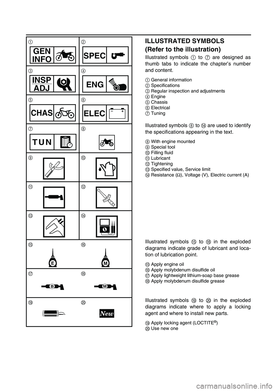
ILLUSTRATED SYMBOLS
(Refer to the illustration)
Illustrated symbols 1 to 7 are designed as
thumb tabs to indicate the chapter’s number
and content.
1General information
2Specifications
3Regular inspection and adjustments
4Engine
5Chassis
6Electrical
7Tuning
Illustrated symbols 8 to D are used to identify
the specifications appearing in the text.
8With engine mounted
9Special tool
0Filling fluid
ALubricant
BTightening
CSpecified value, Service limit
DResistance (
Ω), Voltage (V), Electric current (A)
Illustrated symbols E to H in the exploded
diagrams indicate grade of lubricant and loca-
tion of lubrication point.
EApply engine oil
FApply molybdenum disulfide oil
GApply lightweight lithium-soap base grease
HApply molybdenum disulfide grease
Illustrated symbols I to J in the exploded
diagrams indicate where to apply a locking
agent and where to install new parts.
IApply locking agent (LOCTITE®)
JUse new one 12
34
56
78
90
AB
CD
EF
GH
IJ
GEN
INFOSPEC
INSP
ADJ
ENG
CHAS–+ELEC
TUN
T R..
EM
BM
Page 17 of 676

ABGEBILDETEN SYM-
BOL
(Siehe Abbildung)
Die unter 1 bis 7 abgebildeten
Symbole weisen auf die Themen der
einzelnen Kapitel hin.
1Allgemeine Angaben
2Technische Daten
3Regelmässige Wartungs- und Einstel-
larbeiten
4Motor
5Fahrwerk
6Elektrische Anlage
7Abstimmung
Die Symbole 8 bis D weisen auf
wichtige Angaben im Text hin.
8Wartung mit montiertem Motor mög-
lich
9Spezialwerkzeug
0Art und Menge einzufüllender Flüssig-
keiten
ASchmiermittel
BAnzugsmoment
CVerschleißgrenzen, Toleranzen
DElektrische Sollwerte
Die Symbole E bis H werden in den
Explosionszeichnungen verwendet
und weisen auf Schmier- und Klebe-
mittel sowie die entsprechenden
Stellen hin.
EMotoröl
FMolybdändisulfidöl
GLeichtes Lithiumfett
HMolybdändisulfidfett
Die Symbole I und J werden eben-
falls in den Explosionszeichnungen
verwendet.
IKlebemittel (LOCTITE®)
JNeues Bauteil verwenden
SYMBOLES GRAPHI-
QUES
(Voir l’illustration)
Les symboles graphiques 1 à 7 servent
à repérer les différents chapitres et à
indiquer leur contenu.
1
Renseignements généraux
2
Caractéristiques
3
Controles et réglages periodiques
4
Moteur
5
Chassis
6
Partie électrique
7
Mise au point
Les symboles graphiques 8 à D per-
mettent d’identifier les spécifications
encadrées dans le texte.
8
Avec de montage du moteur
9
Outil spécial
0
Liquide de remplissage
A
Lubrifiant
B
Serrage
C
Valeur spécifiée, limite de service
D
Résistance (Ω
), tension (V), intensité (A)
Les symboles graphiques E à H utilisés
dans les vues en éclaté indiquent les
endroit à lubrifier et le type de lubrifiant.
E
Appliquer de l’huile moteur
F
Appliquer de l’huile au bisulfure de moly-
bdène
G
Appliquer de la graisse fluide à base de
savon au lithium
H
Appliquer de la graisse au bisulfure de
molybdène
Les symboles graphiques I à J dans
les vues en éclaté indiquent le produit de
blocage à appliquer et les pièces qui
nécessitent un remplacement.
I
Appliquer un agent de blocage (LOC-
TITE®)
J
Utiliser une pièce neuve.
SIMBOLI ILLUSTRATI
(Fare riferimento all’illu-
strazione)
I simboli illustrati da 1 a 7 vengono
realizzati come linguette per indicare il
numero del capitolo ed il suo contenuto.
1
Informazioni generali
2
Dati tecnici
3
Controlli e regolazioni periodiche
4
Motore
5
Parte ciclistica
6
Impianto elettrico
7
Messa a punto
I simboli illustrati da 8 a D vengono
impiegati per identificare le specifiche
che compaiono nel testo.
8
A motore montato
9
Utensile speciale
0
Fluido
A
Lubrificante
B
Serraggio
C
Valore specificato, limite
D
Resistenza (Ω
), Tensione (V), Corrente
elettrica (A)
I simboli illustrati da E a H nella rap-
presentazione esplosa indicano il tipo di
lubrificante e l’ubicazione dei punti di
lubrificazione.
E
Impiegare olio motore
F
Impiegare olio di bisolfuro molibdeno
G
Impiegare grasso a base di sapone di litio
leggero
H
Impiegare grasso di bisolfuro di molib-
deno
I simboli illustrati da I a J nella rap-
presentazione esplosa indicano dove
applicare un agente bloccante e dove
installare i nuovi pezzi.
I
Applicare un agente bloccante (LOC-
TITE®)
J
Usare un pezzo nuovo
Page 18 of 676

EC090010
INDEX
GENERAL INFORMATION
SPECIFICATIONS
REGULAR INSPECTION AND ADJUSTMENTS
ENGINE
CHASSIS
ELECTRICAL
TUNING
Page 20 of 676

EC0A0000
CONTENTS
CHAPTER 1
GENERAL INFORMATION
DESCRIPTION
............................................1-1
MACHINE IDENTIFICATION
......................1-2
IMPORTANT INFORMATION
.....................1-3
CHECKING OF CONNECTION
..................1-6
SPECIAL TOOLS
.......................................1-7
CONTROL FUNCTIONS
...........................1-10
FUEL
.........................................................1-13
STARTING AND BREAK-IN
.....................1-14
TORQUE-CHECK POINTS
.......................1-18
CLEANING AND STORAGE
....................1-19
CHAPTER 2
SPECIFICATIONS
GENERAL SPECIFICATIONS
....................2-1
MAINTENANCE SPECIFICATIONS
...........2-4
GENERAL TORQUE
SPECIFICATIONS
....................................2-17
DEFINITION OF UNITS
............................2-17
LUBRICATION DIAGRAMS
.....................2-18
CABLE ROUTING DIAGRAM
..................2-20
CHAPTER 3
REGULAR INSPECTION AND
ADJUSTMENTS
MAINTENANCE INTERVALS
....................3-1
PRE-OPERATION INSPECTION
AND MAINTENANCE
.................................3-4
ENGINE
.......................................................3-5
CHASSIS
..................................................3-23
ELECTRICAL
............................................3-45
Page 26 of 676

GEN
INFO
1 - 1
DESCRIPTION
EC100000
GENERAL INFORMATION
EC110000
DESCRIPTION
1Clutch lever
2Hot starter lever
3Front brake lever
4Throttle grip
5Radiator cap
6Fuel tank cap
7Engine stop switch
8Kickstarter crank
9Fuel tank
0Radiator
ACoolant drain bolt
BRear brake pedal
CValve joint
DFuel cock
ECold starter knob
FDrive chain
GAir filter
HOil level check window
IShift pedal
JFront forkNOTE:
The machine you have purchased may differ
slightly from those shown in the following.
Designs and specifications are subject to
change without notice.
Page 39 of 676

GEN
INFO
1 - 8
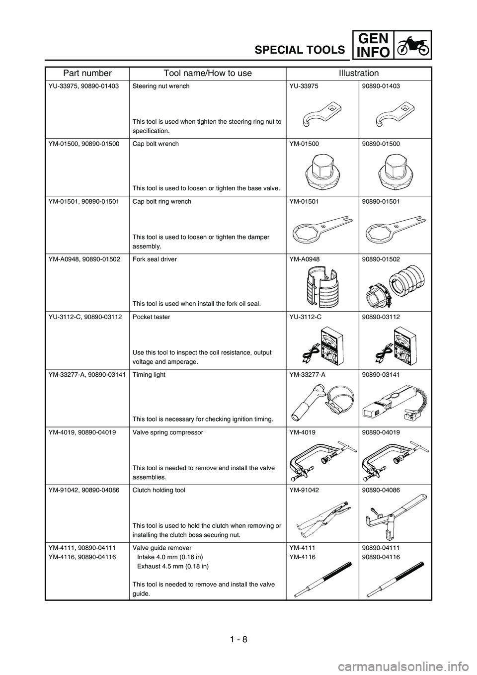
SPECIAL TOOLS
YU-33975, 90890-01403 Steering nut wrench
This tool is used when tighten the steering ring nut to
specification.YU-33975 90890-01403
YM-01500, 90890-01500 Cap bolt wrench
This tool is used to loosen or tighten the base valve.YM-01500 90890-01500
YM-01501, 90890-01501 Cap bolt ring wrench
This tool is used to loosen or tighten the damper
assembly.YM-01501 90890-01501
YM-A0948, 90890-01502 Fork seal driver
This tool is used when install the fork oil seal.YM-A0948 90890-01502
YU-3112-C, 90890-03112 Pocket tester
Use this tool to inspect the coil resistance, output
voltage and amperage.YU-3112-C 90890-03112
YM-33277-A, 90890-03141 Timing light
This tool is necessary for checking ignition timing.YM-33277-A 90890-03141
YM-4019, 90890-04019 Valve spring compressor
This tool is needed to remove and install the valve
assemblies.YM-4019 90890-04019
YM-91042, 90890-04086 Clutch holding tool
This tool is used to hold the clutch when removing or
installing the clutch boss securing nut.YM-91042 90890-04086
YM-4111, 90890-04111
YM-4116, 90890-04116Valve guide remover
Intake 4.0 mm (0.16 in)
Exhaust 4.5 mm (0.18 in)
This tool is needed to remove and install the valve
guide.YM-4111
YM-411690890-04111
90890-04116
Part number Tool name/How to use Illustration