Page 198 of 676

3 - 16
INSP
ADJ
ENGINE OIL REPLACEMENT
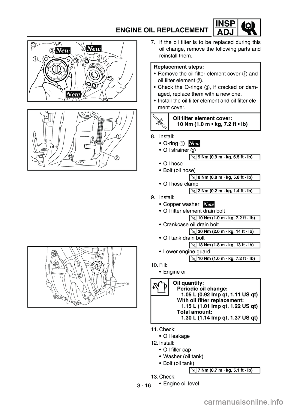
7. If the oil filter is to be replaced during this
oil change, remove the following parts and
reinstall them.
8. Install:
O-ring 1
Oil strainer 2
Oil hose
Bolt (oil hose)
Oil hose clamp
9. Install:
Copper washer
Oil filter element drain bolt
Crankcase oil drain bolt
Oil tank drain bolt
Lower engine guard
10. Fill:
Engine oil
11. Check:
Oil leakage
12. Install:
Oil filler cap
Washer (oil tank)
Bolt (oil tank)
13. Check:
Engine oil level Replacement steps:
Remove the oil filter element cover 1 and
oil filter element 2.
Check the O-rings 3, if cracked or dam-
aged, replace them with a new one.
Install the oil filter element and oil filter ele-
ment cover.
T R..
Oil filter element cover:
10 Nm (1.0 m kg, 7.2 ft lb)
Oil quantity:
Periodic oil change:
1.05 L (0.92 Imp qt, 1.11 US qt)
With oil filter replacement:
1.15 L (1.01 Imp qt, 1.22 US qt)
Total amount:
1.30 L (1.14 Imp qt, 1.37 US qt)
1
2
T R..9 Nm (0.9 m · kg, 6.5 ft · lb)
T R..8 Nm (0.8 m · kg, 5.8 ft · lb)
T R..2 Nm (0.2 m · kg, 1.4 ft · lb)
T R..10 Nm (1.0 m · kg, 7.2 ft · lb)
T R..20 Nm (2.0 m · kg, 14 ft · lb)
T R..18 Nm (1.8 m · kg, 13 ft · lb)
T R..10 Nm (1.0 m · kg, 7.2 ft · lb)
T R..7 Nm (0.7 m · kg, 5.1 ft · lb)
Page 378 of 676
4 - 59
ENG
OIL FILTER ELEMENT, WATER PUMP AND RIGHT
CRANKCASE COVER
REMOVAL POINTS
Impeller shaft
1. Remove:
Impeller 1
Washer 2
Impeller shaft 3
NOTE:
Hold the impeller shaft on its width across the
flats a with spanners, etc. and remove the
impeller.
EC4G3210
Oil seal
NOTE:
It is not necessary to disassemble the water
pump, unless there is an abnormality such as
excessive change in coolant level, discolora-
tion of coolant, or milky transmission oil.
1. Remove:
Bearing 1
2. Remove:
Oil seal 1
INSPECTION
Oil delivery pipe
1. Inspect:
Oil delivery pipe 1
Bend/damage → Replace.
Clogged → Blow.
Page 512 of 676
5 - 24
CHASFRONT BRAKE AND REAR BRAKE
2. Install:
Brake hose holder 1
Screw (brake hose holder) 2
CAUTION:
After installing the brake hose holders,
make sure the brake hose does not contact
the spring (rear shock absorber). If it does,
correct its twist.
Brake fluid
1. Fill:
Brake fluid
Until the fluid level reaches “LOWER”
level line a.
WARNING
Use only the designated quality brake
fluid:
otherwise, the rubber seals may deterio-
rate, causing leakage and poor brake per-
formance.
Refill with the same type of brake fluid;
mixing fluids may result in a harmful
chemical reaction and lead to poor perfor-
mance.
Be careful that water does not enter the
master cylinder when refilling. Water will
significantly lower the boiling point of the
fluid and may result in vapor lock.
CAUTION:
Brake fluid may erode painted surfaces or
plastic parts. Always clean up spilled fluid
immediately.
È
Front
ÉRear
Recommended brake fluid:
DOT #4
T R..2 Nm (0.2 m · kg, 1.4 ft · lb)
È
É
Page 532 of 676
5 - 34
CHASFRONT FORK
5. Measure:
Oil level (left and right) a
Out of specification → Adjust.
Standard oil level:
145 ~ 148 mm (5.71 ~ 5.83 in)
From top of fully stretched
damper assembly.
6. Tighten:
Locknut 1
NOTE:
Fully finger tighten the locknut onto the
damper assembly.
7. Loosen:
Compression damping adjuster 1
NOTE:
Loosen the compression damping adjuster
finger tight.
Record the set position of the adjuster (the
amount of turning out the fully turned in posi-
tion).
8. Install:
Base valve 1
To damper assembly 2.
NOTE:
First bring the damper rod pressure to a maxi-
mum. Then install the base valve while releas-
ing the damper rod pressure.