Page 498 of 794
4 - 89
ENGENGINE REMOVAL
EC4M0000
ENGINE REMOVAL
Extent of removal Order Part name Q’ty Remarks
ENGINE REMOVAL
Preparation for removal Hold the machine by placing the
suitable stand under the frame.
WARNING
Support the machine securely so there is nodanger of it falling over.
Drain the engine oil Refer to “ENGINE OIL REPLACEMENT”
section in the CHAPTER 3.
Seat, fuel tank and side cover Refer to “SEAT, FUEL TANK AND SIDE
COVERS” section.
Radiator Refer to “RADIATOR” section.
Exhaust pipe and silencer Refer to “EXHAUST PIPE AND
SILENCER” section.
Air cut-off valve assembly Refer to “AIR INDUCTION SYSTEM”
section.
Clutch cable and guide Disconnect at the engine side.
Shift pedal Refer to “AC MAGNETO AND
STARTER CLUTCH” section.
Rear shock absorber Refer to “REAR SHOCK ABSORBER”
section in the CHAPTER 6
Carburetor Refer to “CARBURETOR” section.
Page 500 of 794
4 - 90
ENGENGINE REMOVAL
Extent of removal:
1 Engine removal
Extent of removal Order Part name Q’ty Remarks
Cylinder head breather hose Refer to “CAMSHAFTS” section.
Ignition coil
Disconnect the AC magneto lead.
Disconnect the starter motor
lead.Refer to “ELECTRIC STARTING SYS-
TEM” section in the CHAPTER 6.
Negative battery lead Disconnect at the starter motor side.
1 Engine guard 1
2 Neutral switch 1
3 Chain cover 1
4 Nut (drive sprocket) 1
Refer to “REMOVAL POINTS”. 5 Lock washer 1
6 Drive sprocket 1
7Clip 1
8 Bolt (brake pedal) 1
9 Brake pedal 1
1
Page 526 of 794
4 - 103
ENGCRANKCASE AND CRANKSHAFT
5. Install:
Dowel pin 1
O-ring 2
Crankcase (right)
To crankcase (left).
NOTE:
Fit the crankcase (right) onto the crankcase
(left). Tap lightly on the case with soft ham-
mer.
When installing the crankcase, the connect-
ing rod should be positioned at TDC (top
dead center).
New
6. Tighten:
Hose guide 1
Clutch cable holder 2
Bolt (clutch cable holder)
Bolt (crankcase)
NOTE:
Tighten the crankcase tightening bolts in
stage, using a crisscross pattern.
7. Install:
Timing chain
Timing chain guide (rear)
Bolt (timing chain guide)
8. Remove:
Sealant
Forced out on the cylinder mating surface.
9. Apply:
Engine oil
To the crank pin, bearing and oil delivery
hole.
10. Check:
Crankshaft and transmission operation.
Unsmooth operation → Repair.
T R..10 Nm (1.0 m · kg, 7.2 ft · lb)
T R..12 Nm (1.2 m · kg, 8.7 ft · lb)
T R..10 Nm (1.0 m · kg, 7.2 ft · lb)
Page 538 of 794
4 - 109
ENGTRANSMISSION, SHIFT CAM AND SHIFT FORK
6. Install:
Transmission assembly 1
To crankcase (left) 2.
NOTE:
Apply the engine oil on the bearings and guide
bars.
7. Check:
Shifter operation
Transmission operation
Unsmooth operation → Repair.
Page 540 of 794
5 - 1
CHAS
EC500000
CHASSIS
EC590000
FRONT WHEEL AND REAR WHEEL
EC598000
FRONT WHEEL
FRONT WHEEL AND REAR WHEEL
Extent of removal:
1 Front wheel removal
2 Wheel bearing removal
3 Brake disc removal
Extent of removal Order Part name Q’ty Remarks
FRONT WHEEL REMOVAL
WARNING
Support the machine securely so there is nodanger of it falling over.
Preparation for removal Hold the machine by placing the
suitable stand under the engine.
1 Bolt (axle holder) 4 Only loosening.
2 Nut (front wheel axle) 1
3 Front wheel axle 1
4 Front wheel 1
5 Speed sensor 1
6 Collar 1
7 Oil seal 1
8 Bearing 2 Refer to “REMOVAL POINTS”.
9 Brake disc 1
2
13
3
Page 542 of 794
5 - 2
CHAS
EC598100
REAR WHEEL
Extent of removal:
1 Rear wheel removal
2 Wheel bearing removal
3 Brake disc removal
Extent of removal Order Part name Q’ty Remarks
REAR WHEEL REMOVAL
WARNING
Support the machine securely so there is nodanger of it falling over.
Preparation for removal Hold the machine by placing the
suitable stand under the engine.
1 Nut (rear wheel axle) 1
2 Rear wheel axle 1
3 Chain puller 2
4 Rear wheel 1 Refer to “REMOVAL POINTS”.
5 Collar 2
6 Driven sprocket 1
7 Oil seal 2
8 Circlip 1
9 Bearing 2 Refer to “REMOVAL POINTS”.
10 Brake disc 1
3
3
1
2
FRONT WHEEL AND REAR WHEEL
Page 676 of 794

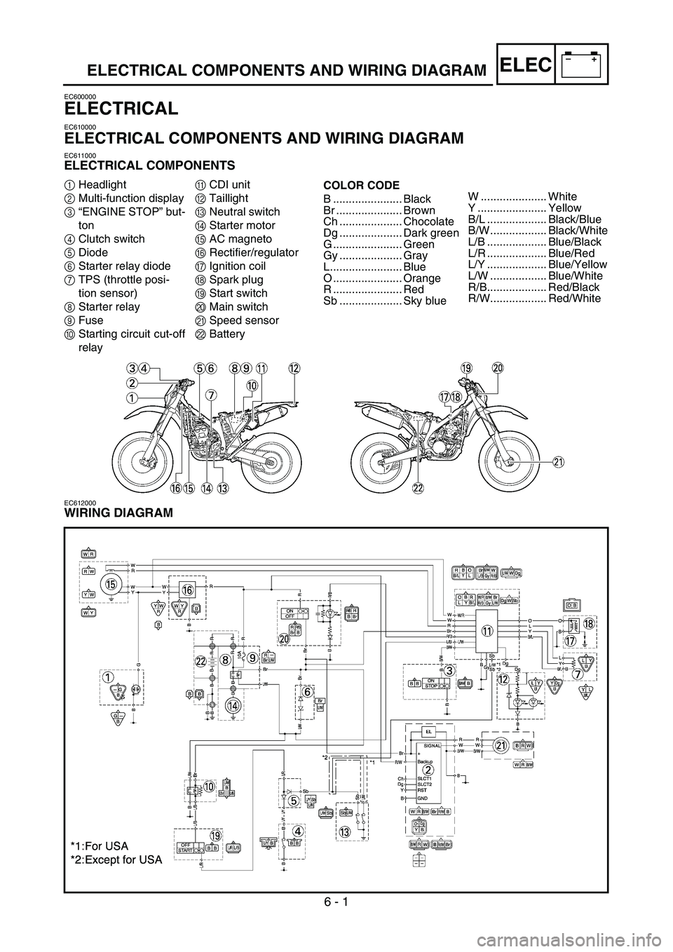
6 - 1
–+ELECELECTRICAL COMPONENTS AND WIRING DIAGRAM
EC600000
ELECTRICAL
EC610000
ELECTRICAL COMPONENTS AND WIRING DIAGRAM
EC611000
ELECTRICAL COMPONENTS
1Headlight
2Multi-function display
3“ENGINE STOP” but-
ton
4Clutch switch
5Diode
6Starter relay diode
7TPS (throttle posi-
tion sensor)
8Starter relay
9Fuse
0Starting circuit cut-off
relayACDI unit
BTaillight
CNeutral switch
DStarter motor
EAC magneto
FRectifier/regulator
GIgnition coil
HSpark plug
IStart switch
JMain switch
KSpeed sensor
LBatteryCOLOR CODE
B ...................... Black
Br ..................... Brown
Ch .................... Chocolate
Dg .................... Dark green
G ...................... Green
Gy .................... Gray
L....................... Blue
O ...................... Orange
R ...................... Red
Sb .................... Sky blue
EC612000
WIRING DIAGRAM
W ..................... White
Y ...................... Yellow
B/L ................... Black/Blue
B/W .................. Black/White
L/B ................... Blue/Black
L/R ................... Blue/Red
L/Y ................... Blue/Yellow
L/W .................. Blue/White
R/B................... Red/Black
R/W.................. Red/White
Page 678 of 794

–+ELEC
6 - 2
IGNITION SYSTEM
EC620000
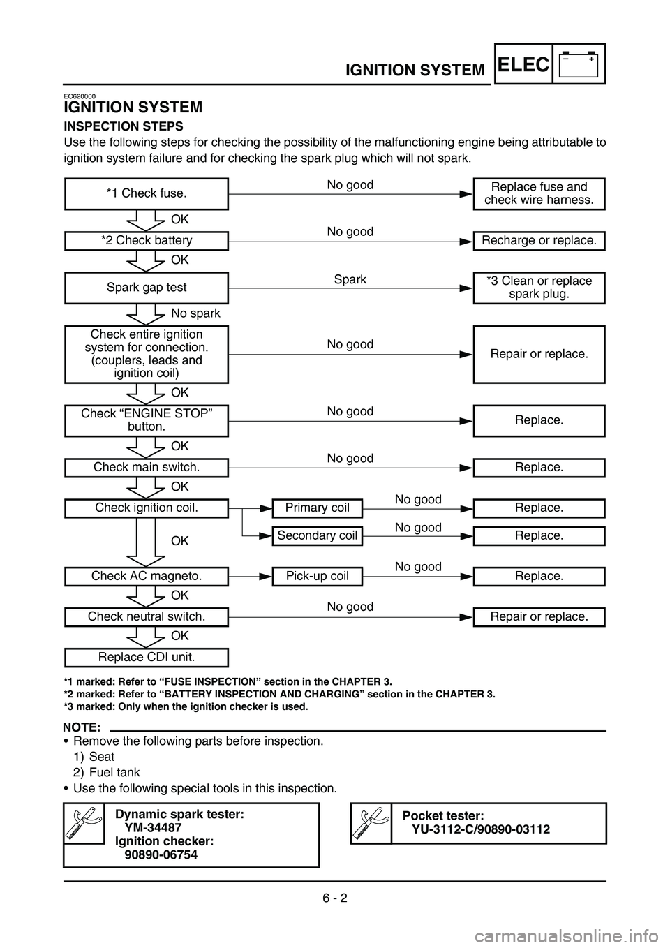
IGNITION SYSTEM
INSPECTION STEPS
Use the following steps for checking the possibility of the malfunctioning engine being attributable to
ignition system failure and for checking the spark plug which will not spark.
*1 marked: Refer to “FUSE INSPECTION” section in the CHAPTER 3.
*2 marked: Refer to “BATTERY INSPECTION AND CHARGING” section in the CHAPTER 3.
*3 marked: Only when the ignition checker is used.
NOTE:
•Remove the following parts before inspection.
1) Seat
2) Fuel tank
•Use the following special tools in this inspection.
Dynamic spark tester:
YM-34487
Ignition checker:
90890-06754Pocket tester:
YU-3112-C/90890-03112
*1 Check fuse.Replace fuse and
check wire harness.
*2 Check battery Recharge or replace.
Spark gap test*3 Clean or replace
spark plug.
Check entire ignition
system for connection.
(couplers, leads and
ignition coil)Repair or replace.
Check “ENGINE STOP”
button.Replace.
Check main switch. Replace.
Check ignition coil. Primary coil Replace.
Secondary coil Replace.
Check AC magneto. Pick-up coil Replace.
Check neutral switch. Repair or replace.
Replace CDI unit.
OK
OK
No spark
OK
OK
OK
OK
OK
OK
Spark No good
No good
No good
No good
No good No good
No good
No good
No good