Page 92 of 794
SPEC
2 - 3 Brake:
Front brake type Single disc brake
Operation Right hand operation
Rear brake type Single disc brake
Operation Right foot operation
Suspension:
Front suspension Telescopic fork
Rear suspension Swingarm (link type monocross suspension)
Shock absorber:
Front shock absorber Coil spring/oil damper
Rear shock absorber Coil spring/gas, oil damper
Wheel travel:
Front wheel travel 300 mm (11.8 in)
Rear wheel travel 305 mm (12.0 in)
Electrical:
Ignition system CDI
Generator system AC magneto
Battery type YTZ7S
Battery voltage/capacity 12 V/6 AH
Specific gravity 1.310
Headlight type: Quartz bulb (halogen)
Bulb wattage × quantity:
Headlight 12 V 35/36.5 W × 1
Taillight 12 V 1.6/0.3 W × 1
GENERAL SPECIFICATIONS
Page 694 of 794

6 - 8
–+ELECELECTRIC STARTING SYSTEM
EC624000
COUPLERS AND LEADS CONNECTION
INSPECTION
1. Check:
•Couplers and leads connection
Rust/dust/looseness/short-circuit →
Repair or replace.
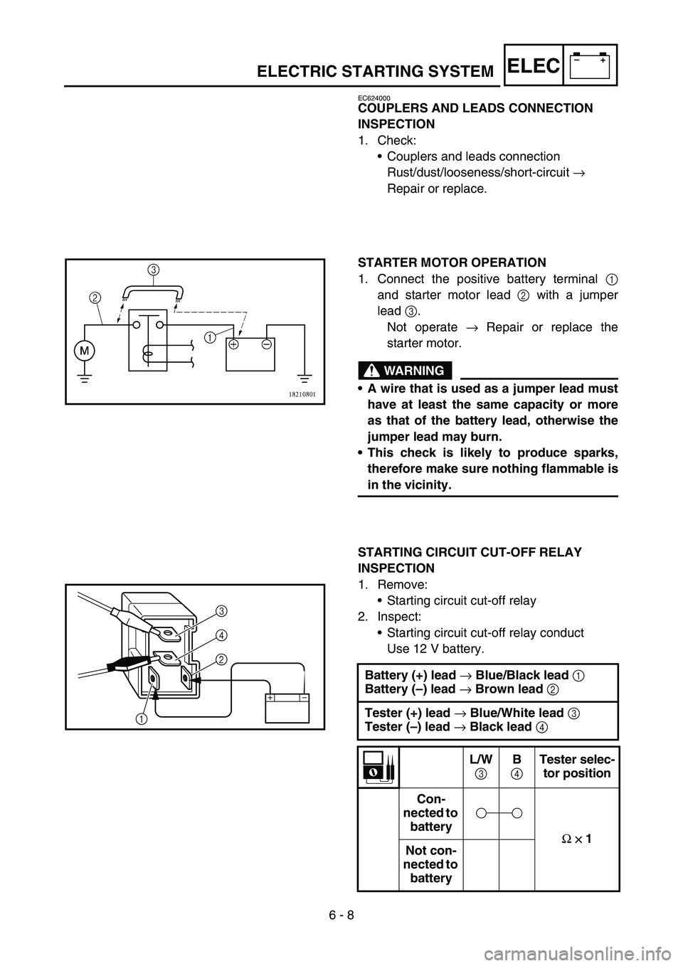
STARTER MOTOR OPERATION
1. Connect the positive battery terminal 1
and starter motor lead 2 with a jumper
lead 3.
Not operate → Repair or replace the
starter motor.
WARNING
A wire that is used as a jumper lead must
have at least the same capacity or more
as that of the battery lead, otherwise the
jumper lead may burn.
This check is likely to produce sparks,
therefore make sure nothing flammable is
in the vicinity.
STARTING CIRCUIT CUT-OFF RELAY
INSPECTION
1. Remove:
•Starting circuit cut-off relay
2. Inspect:
•Starting circuit cut-off relay conduct
Use 12 V battery.
Battery (+) lead
→ Blue/Black lead
1
Battery (–) lead
→ Brown lead
2
Tester (+) lead
→ Blue/White lead
3
Tester (–) lead
→ Black lead
4
L/W
3 B
4 Tester selec-
tor position
Con-
nected to
battery
Ω
×
×× × 1
Not con-
nected to
battery
2 4
3
1
Page 732 of 794
6 - 24
–+ELECLIGHTING SYSTEM
CHECKING THE TAILLIGHT (LEDs)
1. Disconnect the taillight coupler.
2. Connect two jumper leads 1 from the bat-
tery terminals to the respective coupler ter-
minal as shown.
3. Check:
•LED (for proper operation)
Does not light → Replace the taillight
assembly.
WARNING
A wire that is used as a jumper lead must
have at least the same capacity of the bat-
tery lead, otherwise the jumper lead may
burn.
This check is likely to produce sparks,
therefore, make sure no flammable gas or
fluid is in the vicinity.
Battery (+) terminal →
Blue lead
2
Battery (–) terminal →
Black lead
3
AC MAGNETO INSPECTION
1. Inspect:
•Lighting coil resistance
Out of specification → Replace.
Tester (+) lead
→ Yellow lead
1
Tester (–) lead
→ Ground
2
Lighting coil
resistanceTester selector
position
0.224 ~ 0.336
Ω
at 20 °C (68 °F)Ω
× 1