Page 38 of 794
GEN
INFO
1 - 7
EC140001
SPECIAL TOOLS
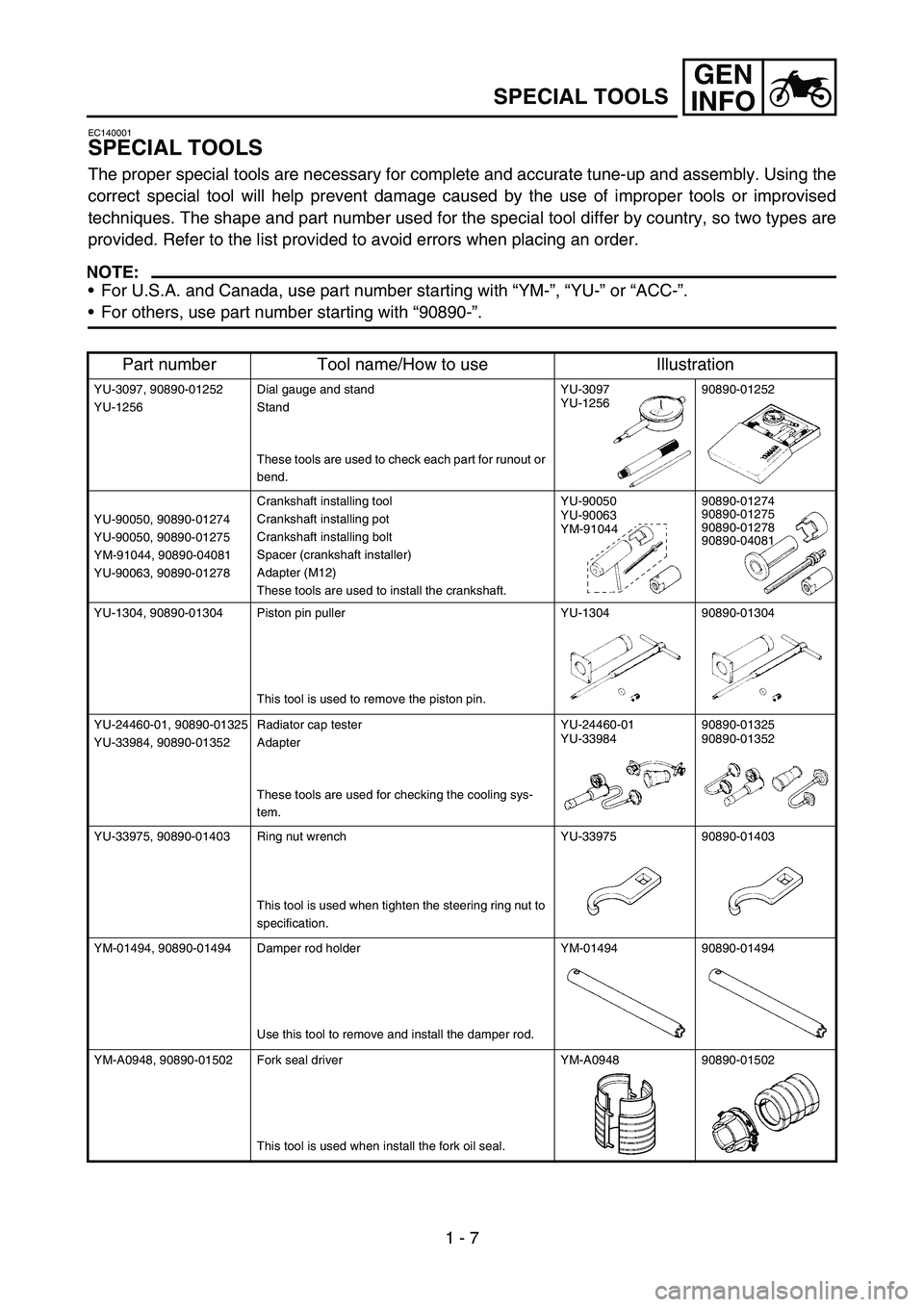
The proper special tools are necessary for complete and accurate tune-up and assembly. Using the
correct special tool will help prevent damage caused by the use of improper tools or improvised
techniques. The shape and part number used for the special tool differ by country, so two types are
provided. Refer to the list provided to avoid errors when placing an order.
NOTE:
For U.S.A. and Canada, use part number starting with “YM-”, “YU-” or “ACC-”.
For others, use part number starting with “90890-”.
Part number Tool name/How to use Illustration
YU-3097, 90890-01252
YU-1256Dial gauge and stand
Stand
These tools are used to check each part for runout or
bend.YU-3097
YU-125690890-01252
YU-90050, 90890-01274
YU-90050, 90890-01275
YM-91044, 90890-04081
YU-90063, 90890-01278Crankshaft installing tool
Crankshaft installing pot
Crankshaft installing bolt
Spacer (crankshaft installer)
Adapter (M12)
These tools are used to install the crankshaft.YU-90050
YU-90063
YM-9104490890-01274
90890-01275
90890-01278
90890-04081
YU-1304, 90890-01304 Piston pin puller
This tool is used to remove the piston pin.YU-1304 90890-01304
YU-24460-01, 90890-01325
YU-33984, 90890-01352Radiator cap tester
Adapter
These tools are used for checking the cooling sys-
tem.YU-24460-01
YU-3398490890-01325
90890-01352
YU-33975, 90890-01403 Ring nut wrench
This tool is used when tighten the steering ring nut to
specification.YU-33975 90890-01403
YM-01494, 90890-01494 Damper rod holder
Use this tool to remove and install the damper rod.YM-01494 90890-01494
YM-A0948, 90890-01502 Fork seal driver
This tool is used when install the fork oil seal.YM-A0948 90890-01502
SPECIAL TOOLS
Page 39 of 794
GEN
INFO
1 - 8
SPECIAL TOOLS
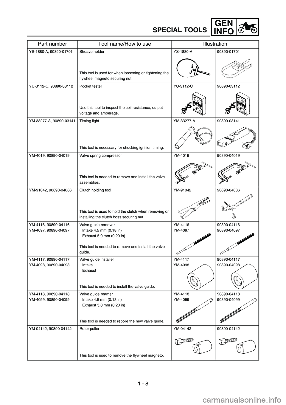
YS-1880-A, 90890-01701 Sheave holder
This tool is used for when loosening or tightening the
flywheel magneto securing nut.YS-1880-A 90890-01701
YU-3112-C, 90890-03112 Pocket tester
Use this tool to inspect the coil resistance, output
voltage and amperage.YU-3112-C 90890-03112
YM-33277-A, 90890-03141 Timing light
This tool is necessary for checking ignition timing.YM-33277-A 90890-03141
YM-4019, 90890-04019 Valve spring compressor
This tool is needed to remove and install the valve
assemblies.YM-4019 90890-04019
YM-91042, 90890-04086 Clutch holding tool
This tool is used to hold the clutch when removing or
installing the clutch boss securing nut.YM-91042 90890-04086
YM-4116, 90890-04116
YM-4097, 90890-04097Valve guide remover
Intake 4.5 mm (0.18 in)
Exhaust 5.0 mm (0.20 in)
This tool is needed to remove and install the valve
guide.YM-4116
YM-409790890-04116
90890-04097
YM-4117, 90890-04117
YM-4098, 90890-04098Valve guide installer
Intake
Exhaust
This tool is needed to install the valve guide.YM-4117
YM-409890890-04117
90890-04098
YM-4118, 90890-04118
YM-4099, 90890-04099Valve guide reamer
Intake 4.5 mm (0.18 in)
Exhaust 5.0 mm (0.20 in)
This tool is needed to rebore the new valve guide.YM-4118
YM-4099 90890-04118
90890-04099
YM-04142, 90890-04142 Rotor puller
This tool is used to remove the flywheel magneto.YM-04142 90890-04142
Part number Tool name/How to use Illustration
Page 226 of 794
3 - 14
INSP
ADJ
ENGINE OIL LEVEL INSPECTION
ENGINE OIL LEVEL INSPECTION
1. Stand the machine on a level surface.
NOTE:
When checking the oil level make sure that
the machine is upright.
Place the machine on a suitable stand.
WARNING
Never remove the oil tank cap just after
high speed operation. The heated oil could
spurt out. causing danger. Wait until the oil
cools down to approximately 70 °C (158 °F).
2. Idle the engine more than 3 minutes while
keeping the machine upright. Then stop the
engine and inspect the oil level.
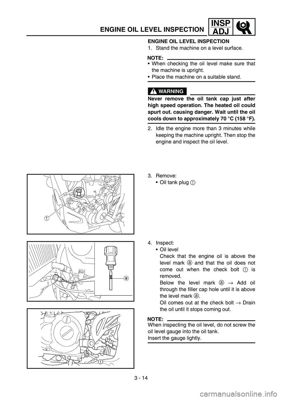
3. Remove:
Oil tank plug 1
4. Inspect:
Oil level
Check that the engine oil is above the
level mark a and that the oil does not
come out when the check bolt 1 is
removed.
Below the level mark a → Add oil
through the filler cap hole until it is above
the level mark a.
Oil comes out at the check bolt → Drain
the oil until it stops coming out.
NOTE:
When inspecting the oil level, do not screw the
oil level gauge into the oil tank.
Insert the gauge lightly.
Page 234 of 794
3 - 18
INSP
ADJ
IDLE SPEED ADJUSTMENT
9. Check:
Oil pressure
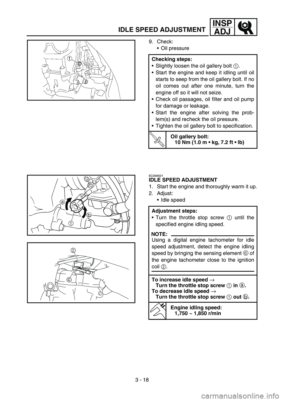
Checking steps:
Slightly loosen the oil gallery bolt 1.
Start the engine and keep it idling until oil
starts to seep from the oil gallery bolt. If no
oil comes out after one minute, turn the
engine off so it will not seize.
Check oil passages, oil filter and oil pump
for damage or leakage.
Start the engine after solving the prob-
lem(s) and recheck the oil pressure.
Tighten the oil gallery bolt to specification.
T R..
Oil gallery bolt:
10 Nm (1.0 m kg, 7.2 ft lb)
EC35M021
IDLE SPEED ADJUSTMENT
1. Start the engine and thoroughly warm it up.
2. Adjust:
Idle speed
Adjustment steps:
Turn the throttle stop screw 1 until the
specified engine idling speed.
NOTE:
Using a digital engine tachometer for idle
speed adjustment, detect the engine idling
speed by bringing the sensing element c of
the engine tachometer close to the ignition
coil 2.
To increase idle speed
→
Turn the throttle stop screw
1 in
a.
To decrease idle speed
→
Turn the throttle stop screw
1 out
b.
Engine idling speed:
1,750 ~ 1,850 r/min
c2
Page 378 of 794
4 - 29
ENGCAMSHAFTS
Decompression system
1. Check:
Decompression system
Checking steps:
Check that the decompressor cam 1
moves smoothly.
Check that the decompressor lever pin 2
projects from the camshaft.
Timing chain tensioner
1. Check:
While pressing the tensioner rod lightly
with fingers, use a thin screwdriver 1
and wind the tensioner rod up fully clock-
wise.
When releasing the screwdriver by press-
ing lightly with fingers, make sure that the
tensioner rod will come out smoothly.
If not, replace the tensioner assembly.
ASSEMBLY AND INSTALLATION
1. Install:
Exhaust camshaft 1
Intake camshaft 2
Installation steps:
Turn the crankshaft counterclockwise until
the “I” mark a on the rotor is aligned with
the stationary pointer b on the crankcase
cover.
NOTE:
Apply the molybdenum disulfide oil on the
camshafts.
Apply the engine oil on the decompression
system.
Page 608 of 794
5 - 35
CHASFRONT FORK
19. Wait ten minutes until the air bubbles have
been removed from the front fork, and the
oil has dispense evenly in system before
setting recommended oil level.
NOTE:
Fill with the fork oil up to the top end of the
outer tube, or the fork oil will not spread over to
every part of the front forks, thus making it
impossible to obtain the correct level.
Be sure to fill with the fork oil up to the top of
the outer tube and bleed the front forks.
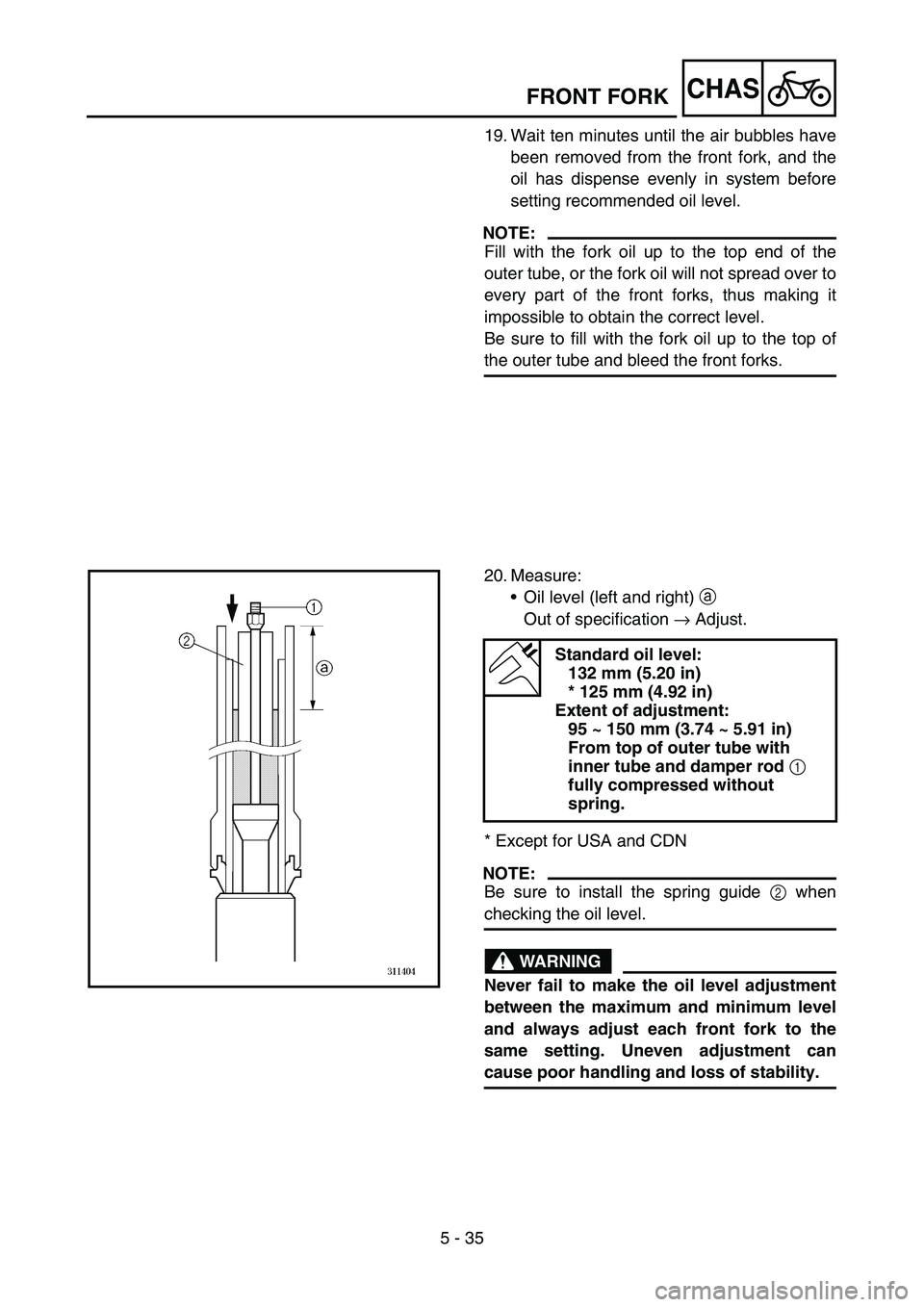
20. Measure:
Oil level (left and right) a
Out of specification → Adjust.
* Except for USA and CDN
NOTE:
Be sure to install the spring guide 2 when
checking the oil level.
WARNING
Never fail to make the oil level adjustment
between the maximum and minimum level
and always adjust each front fork to the
same setting. Uneven adjustment can
cause poor handling and loss of stability.
Standard oil level:
132 mm (5.20 in)
* 125 mm (4.92 in)
Extent of adjustment:
95 ~ 150 mm (3.74 ~ 5.91 in)
From top of outer tube with
inner tube and damper rod
1
fully compressed without
spring.
Page 678 of 794
–+ELEC
6 - 2
IGNITION SYSTEM
EC620000
IGNITION SYSTEM
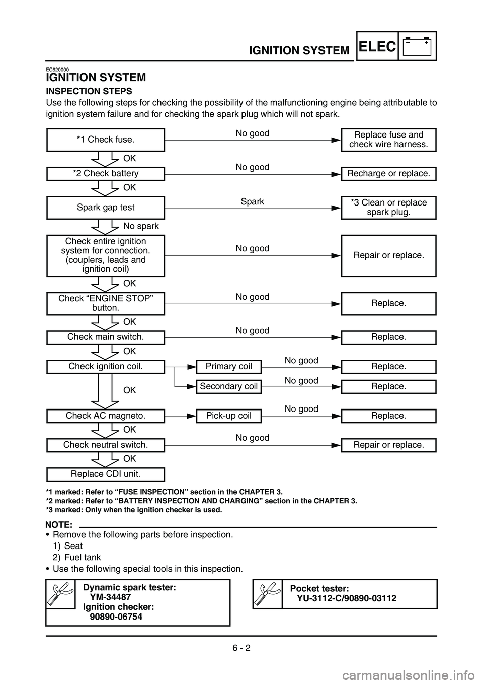
INSPECTION STEPS
Use the following steps for checking the possibility of the malfunctioning engine being attributable to
ignition system failure and for checking the spark plug which will not spark.
*1 marked: Refer to “FUSE INSPECTION” section in the CHAPTER 3.
*2 marked: Refer to “BATTERY INSPECTION AND CHARGING” section in the CHAPTER 3.
*3 marked: Only when the ignition checker is used.
NOTE:
•Remove the following parts before inspection.
1) Seat
2) Fuel tank
•Use the following special tools in this inspection.
Dynamic spark tester:
YM-34487
Ignition checker:
90890-06754Pocket tester:
YU-3112-C/90890-03112
*1 Check fuse.Replace fuse and
check wire harness.
*2 Check battery Recharge or replace.
Spark gap test*3 Clean or replace
spark plug.
Check entire ignition
system for connection.
(couplers, leads and
ignition coil)Repair or replace.
Check “ENGINE STOP”
button.Replace.
Check main switch. Replace.
Check ignition coil. Primary coil Replace.
Secondary coil Replace.
Check AC magneto. Pick-up coil Replace.
Check neutral switch. Repair or replace.
Replace CDI unit.
OK
OK
No spark
OK
OK
OK
OK
OK
OK
Spark No good
No good
No good
No good
No good No good
No good
No good
No good
Page 714 of 794
6 - 17
–+ELECCHARGING SYSTEM
EC624000
COUPLERS AND LEADS CONNECTION
INSPECTION
1. Check:
•Couplers and leads connection
Rust/dust/looseness/short-circuit →
Repair or replace.
CHARGING VOLTAGE INSPECTION
1. Start the engine.
2. Inspect:
•Charging voltage
Out of specification → If no failure is
found in checking the source coil resis-
tance, replace the rectifier/regulator.
Tester (+) lead
→ Red lead
1
Tester (–) lead
→ Black lead
2
Charging
voltageTester selector
position
14.0 ~ 15.0 V at
5,000 r/minDCV-20
R
BW Y1
2
3. Inspect:
•Charging coil resistance
Out of specification → Replace.
Tester (+) lead
→ White lead
1
Tester (–) lead
→ Ground
2
Charging coil
resistanceTester selector
position
0.288 ~ 0.432
Ω
at 20 °C (68 °F)Ω
× 1