Page 78 of 156
 are interconnected by the
drive train. This means that applying either the
front brake or the rear brake will brake all wheels.
W")
7-18
7When this ATV is in 4WD or 4WD-LOCK, all
wheels (front and rear) are interconnected by the
drive train. This means that applying either the
front brake or the rear brake will brake all wheels.
When descending hills, using either brake lever or
the brake pedal will brake the wheels on the down-
hill side. Avoid sudden application of either the
front or rear brake because the wheels on the up-
hill side could come off the ground. Apply both the
front and rear brakes gradually.
Whenever possible, ride your ATV straight down-
hill. Avoid sharp angles which could allow the ATV
to tip or roll over. Carefully choose your path and
ride no faster than you will be able to react to ob-
stacles which may appear.
WARNING
EWB01620Always follow proper procedures for going
down hills as described in this Owner’s Manu-
al.
Note: a special technique is required when
braking as you go down a hill.�Always check the terrain carefully before
you start down any hill.�Shift your weight backward.�Never go down a hill at high speed.
�Avoid going down a hill at an angle that
would cause the ATV to lean sharply to one
side. Go straight down the hill where possi-ble.
CROSSING A SLOPE
Traversing a sloping surface on your ATV requires
you to properly position your weight to maintain
proper balance. Be sure that you have learned the
basic riding skills on flat ground before attempting
U2C661E0.book Page 18 Thursday, March 16, 2006 10:45 AM
Page 114 of 156
8-30
84. Remove the sponge material from the air filter
element frame.
5. Wash the sponge material gently but thor-
oughly in solvent.
WARNING
EWB01940Always use parts cleaning solvent to clean the
sponge material. Never use low-flash-point
solvents or gasoline to clean the sponge mate-
rial because the engine could catch fire or ex-plode.
6. Squeeze the excess solvent out of the sponge
material and let it dry.
1. Air filter element
1. Unlock.
1. Air filter element frame
2. Sponge material
U2C661E0.book Page 30 Thursday, March 16, 2006 10:45 AM
Page 119 of 156

8-35
8 4. Check the engine idling speed and, if neces-
sary, adjust it to specification by turning the
throttle stop screw at the carburetor. To in-
crease the engine idling speed, turn the throt-
tle stop screw in direction (a), and to decrease
it, turn the screw in direction (b).
NOTE:If the specified idling speed cannot be obtained as
described above, have a Yamaha dealer make theadjustment.5. Install the panel.
EBU24043Adjusting the throttle cable free play The throttle cable free play should be checked
and, if necessary, adjusted at the intervals speci-
fied in the periodic maintenance and lubrication
chart.
The throttle cable free play should measure 3.0–
5.0 mm (0.12–0.20 in) at the throttle lever. Period-
ically check the throttle cable free play and, if nec-
essary, adjust it as follows.NOTE:The engine idling speed must be checked, and ad-
justed if necessary, before adjusting the throttle ca-ble free play.
1. Loosen the locknut.
2. To increase the throttle cable free play, turn
the adjusting bolt in direction (a). To decrease
the throttle cable free play, turn the adjusting
bolt in direction (b).
1. Throttle stop screwEngine idling speed:
1450–1550 r/min
U2C661E0.book Page 35 Thursday, March 16, 2006 10:45 AM
Page 120 of 156

8-36
83. Tighten the locknut.
EBU24060Valve clearance The valve clearance changes with use, resulting in
improper air-fuel mixture and/or engine noise. To
prevent this from occurring, the valve clearance
must be adjusted by a Yamaha dealer at the inter-
vals specified in the periodic maintenance and lu-
brication chart.
EBU24070Adjusting the drive select lever safety
system cable The drive select lever safety system cable stretch-
es with use, which can result in improper function.
Therefore, the safety system cable should be
checked and adjusted at the intervals specified in
the periodic maintenance and lubrication chart.EBU24130Checking the front and rear brake pads The front and rear brake pads must be checked for
wear at the intervals specified in the periodic main-
tenance and lubrication chart.EBU24171Front brake pads
Check each front brake pad for damage and mea-
sure the lining thickness. If a brake pad is dam-
aged or if the lining thickness is less than 1.0 mm
(0.04 in), have a Yamaha dealer replace the brake
pads as a set.
1. Locknut
2. Throttle cable free play adjusting bolt
3. Throttle cable free playU2C661E0.book Page 36 Thursday, March 16, 2006 10:45 AM
Page 122 of 156
8-38
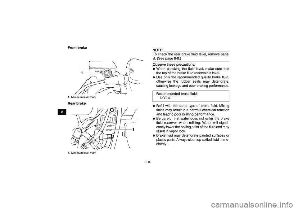
8Front brake
Rear brake
NOTE:To check the rear brake fluid level, remove panelB. (See page 8-8.)
Observe these precautions:�When checking the fluid level, make sure that
the top of the brake fluid reservoir is level.�Use only the recommended quality brake fluid,
otherwise the rubber seals may deteriorate,
causing leakage and poor braking performance.�Refill with the same type of brake fluid. Mixing
fluids may result in a harmful chemical reaction
and lead to poor braking performance.�Be careful that water does not enter the brake
fluid reservoir when refilling. Water will signifi-
cantly lower the boiling point of the fluid and may
result in vapor lock.�Brake fluid may deteriorate painted surfaces or
plastic parts. Always clean up spilled fluid imme-
diately.
1. Minimum level mark
1. Minimum level mark
Recommended brake fluid:
DOT 4
U2C661E0.book Page 38 Thursday, March 16, 2006 10:45 AM
Page 124 of 156
8-40
8
EBU27140Adjusting the rear brake lever free play
and checking the brake pedal position The brake lever free play must be adjusted and
brake pedal position must be checked and, if nec-
essary, adjusted at the intervals specified in the
periodic maintenance and lubrication chart.NOTE:�Always perform this maintenance completely in
the following order whenever adjusting the rear
brake.�Before adjusting the brake lever free play and
checking the brake pedal position, check therear brake pads for wear.
Adjusting the brake lever free play
The brake lever free play should measure 0.5–2.0
mm (0.02–0.08 in) as shown. If the free play is in-
correct, adjust it as follows.1. Loosen the locknut.
2. Turn the brake lever free play adjusting bolt in
direction (a) to increase the free play, and in
direction (b) to decrease it.
1. Brake lever free play
U2C661E0.book Page 40 Thursday, March 16, 2006 10:45 AM
Page 125 of 156
8-41
8 3. Tighten the locknut.
If the correct free play cannot be obtained, have a
Yamaha dealer adjust it.
NOTE:When adjusting the rear brake lever free play:�Be sure not to step on the brake pedal.�Make sure the brake pedal does not move.Checking the brake pedal position
The top of the brake pedal should be positioned
72.0 mm (2.83 in) above the top of the footboard.
If the brake pedal position is incorrect, have a
Yamaha dealer adjust it.
WARNING
EWB02070Operating with improperly serviced or adjust-
ed brakes could cause loss of braking ability,
which could lead to an accident.
After servicing:�Make sure the brakes operate smoothly and
that the free play is correct.�Make sure the brakes do not drag.
1. Locknut
2. Brake lever free play adjusting bolt
1. Distance between brake pedal and footboard
U2C661E0.book Page 41 Thursday, March 16, 2006 10:45 AM
Page 132 of 156
8-48
8
EBU25322Replacing a fuse The main fuse and the fuse box are located under
the seat. (See page 4-18.)
If a fuse is blown, replace it as follows.
1. Turn the key to “OFF” and turn off all electrical
circuits.
CAUTION:ECB00640To prevent accidental short-circuiting, turn off
the main switch when checking or replacing afuse.
2. Remove the blown fuse, and then install a
new fuse of the specified amperage.
1. Main fuse
2. Spare main fuse
3. Headlight fuse
4. Ignition fuse
5. Auxiliary DC jack fuse
6. Four-wheel-drive motor fuse
7. Signaling system fuse
8. Backup fuse (for odometer and clock)
9. Spare fuse
Specified fuses:
Main fuse:
30.0 A
Headlight fuse:
15.0 A
Ignition fuse:
10.0 A
Four-wheel-drive motor fuse:
3.0 A
Signaling system fuse:
10.0 A
Auxiliary DC jack fuse:
10.0 A
Backup fuse:
10.0 A
U2C661E0.book Page 48 Thursday, March 16, 2006 10:45 AM


If a fuse is blown, replace it as follows.
1. Turn the key to “OFF” and turn off all ele")