Page 25 of 94

INSTRUMENT AND CONTROL FUNCTIONS
3-11
3
EAU12733
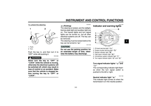
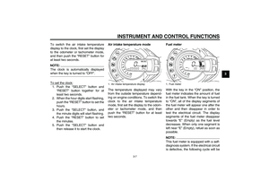
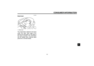
Hazard switch “”
With the key in the “ON” or “” posi-
tion, use this switch to turn on the haz-
ard lights (simultaneous flashing of all
turn signal lights).
The hazard lights are used in case of
an emergency or to warn other drivers
when your vehicle is stopped where it
might be a traffic hazard.CAUTION:
ECA10061
Do not use the hazard lights for an
extended length of time with the en-
gine not running, otherwise the bat-tery may discharge.
EAU12820
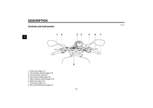
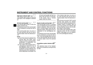
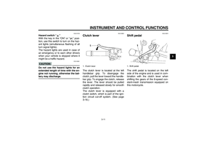
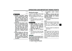
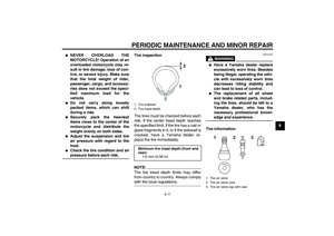
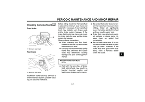
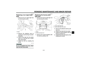
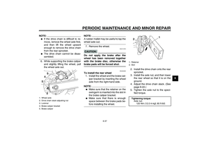
Clutch lever The clutch lever is located at the left
handlebar grip. To disengage the
clutch, pull the lever toward the handle-
bar grip. To engage the clutch, release
the lever. The lever should be pulled
rapidly and released slowly for smooth
clutch operation.
The clutch lever is equipped with a
clutch switch, which is part of the igni-
tion circuit cut-off system. (See page
3-18.)
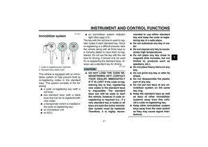
EAU12870
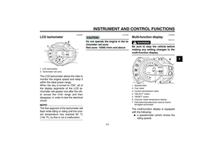
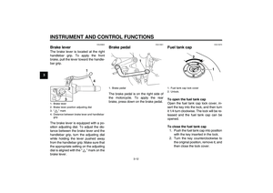
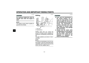
Shift pedal The shift pedal is located on the left
side of the engine and is used in com-
bination with the clutch lever when
shifting the gears of the 6-speed con-
stant-mesh transmission equipped on
this motorcycle.
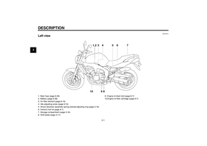
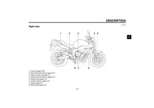
1. Clutch lever
1. Shift pedal
U1B3E3E0.book Page 11 Friday, July 14, 2006 11:34 AM
Page 26 of 94

INSTRUMENT AND CONTROL FUNCTIONS
3-12
3
EAU26822
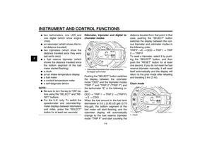
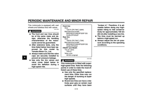
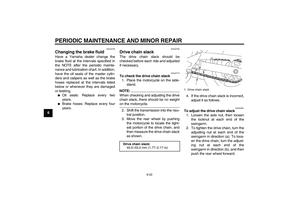
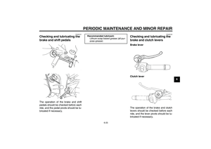
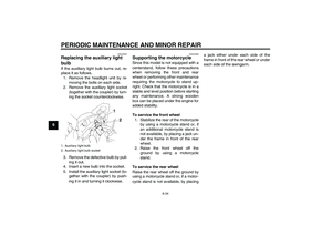
Brake lever The brake lever is located at the right
handlebar grip. To apply the front
brake, pull the lever toward the handle-
bar grip.
The brake lever is equipped with a po-
sition adjusting dial. To adjust the dis-
tance between the brake lever and the
handlebar grip, turn the adjusting dial
while holding the lever pushed away
from the handlebar grip. Make sure that
the appropriate setting on the adjusting
dial is aligned with the “” mark on the
brake lever.
EAU12941
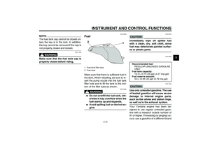
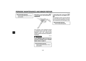
Brake pedal The brake pedal is on the right side of
the motorcycle. To apply the rear
brake, press down on the brake pedal.
EAU13070
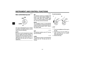
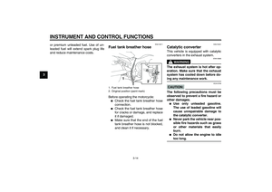
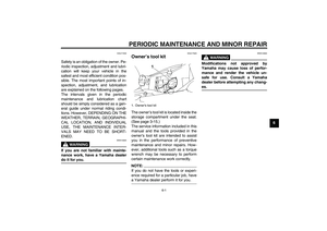
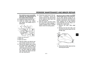
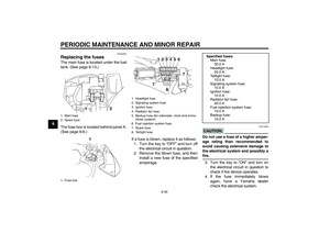
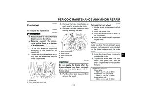
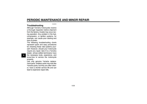
Fuel tank cap To open the fuel tank cap
Open the fuel tank cap lock cover, in-
sert the key into the lock, and then turn
it 1/4 turn clockwise. The lock will be re-
leased and the fuel tank cap can be
opened.
To close the fuel tank cap
1. Push the fuel tank cap into position
with the key inserted in the lock.
2. Turn the key counterclockwise to
the original position, remove it, and
then close the lock cover.
1. Brake lever
2. Brake lever position adjusting dial
3.“” mark
4. Distance between brake lever and handlebar
grip
1. Brake pedal
1. Fuel tank cap lock cover
2. Unlock.
U1B3E3E0.book Page 12 Friday, July 14, 2006 11:34 AM
Page 27 of 94

INSTRUMENT AND CONTROL FUNCTIONS
3-13
3
NOTE:The fuel tank cap cannot be closed un-
less the key is in the lock. In addition,
the key cannot be removed if the cap isnot properly closed and locked.
WARNING
EWA11090
Make sure that the fuel tank cap isproperly closed before riding.
EAU13220
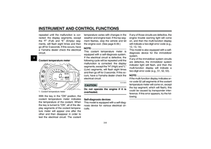
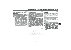
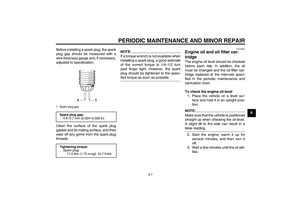
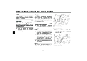
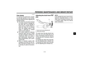
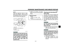
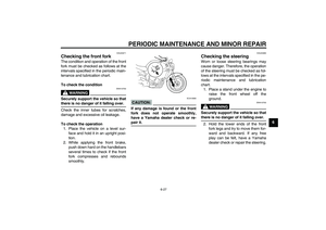
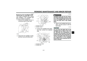
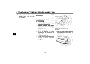
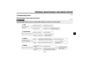
Fuel Make sure that there is sufficient fuel in
the tank. When refueling, be sure to in-
sert the pump nozzle into the fuel tank
filler hole and to fill the tank to the bot-
tom of the filler tube as shown.
WARNING
EWA10880
�
Do not overfill the fuel tank, oth-
erwise it may overflow when the
fuel warms up and expands.
�
Avoid spilling fuel on the hot en-gine.
CAUTION:
ECA10070
Immediately wipe off spilled fuel
with a clean, dry, soft cloth, since
fuel may deteriorate painted surfac-es or plastic parts.
EAU13320
CAUTION:
ECA11400
Use only unleaded gasoline. The use
of leaded gasoline will cause severe
damage to internal engine parts,
such as the valves and piston rings,as well as to the exhaust system.
Your Yamaha engine has been de-
signed to use regular unleaded gaso-
line with a research octane number of
91 or higher. If knocking (or pinging) oc-
curs, use a gasoline of a different brand
1. Fuel tank filler tube
2. Fuel level
Recommended fuel:
REGULAR UNLEADED GASOLINE
ONLY
Fuel tank capacity:
19.4 L (5.13 US gal) (4.27 Imp.gal)
Fuel reserve amount:
3.6 L (0.95 US gal) (0.79 Imp.gal)
U1B3E3E0.book Page 13 Friday, July 14, 2006 11:34 AM
Page 28 of 94

INSTRUMENT AND CONTROL FUNCTIONS
3-14
3or premium unleaded fuel. Use of un-
leaded fuel will extend spark plug life
and reduce maintenance costs.
EAU13411
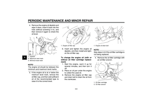
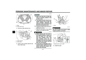
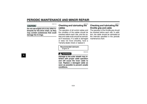
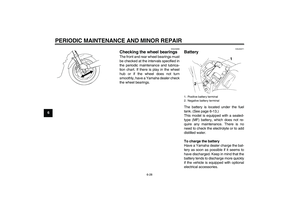
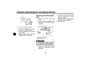
Fuel tank breather hose Before operating the motorcycle:�
Check the fuel tank breather hose
connection.
�
Check the fuel tank breather hose
for cracks or damage, and replace
it if damaged.
�
Make sure that the end of the fuel
tank breather hose is not blocked,
and clean it if necessary.
EAU13441
Catalytic converter This vehicle is equipped with catalytic
converters in the exhaust system.
WARNING
EWA10860
The exhaust system is hot after op-
eration. Make sure that the exhaust
system has cooled down before do-ing any maintenance work.CAUTION:
ECA10700
The following precautions must be
observed to prevent a fire hazard or
other damages.�
Use only unleaded gasoline.
The use of leaded gasoline will
cause unrepairable damage to
the catalytic converter.
�
Never park the vehicle near pos-
sible fire hazards such as grass
or other materials that easily
burn.
�
Do not allow the engine to idletoo long.
1. Fuel tank breather hose
2. Original position (paint mark)
U1B3E3E0.book Page 14 Friday, July 14, 2006 11:34 AM
Page 29 of 94
INSTRUMENT AND CONTROL FUNCTIONS
3-15
3
EAU32980
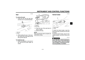
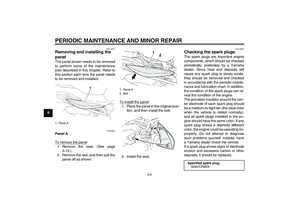
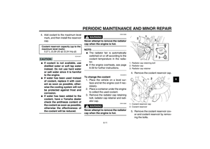
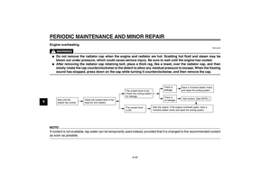
Seat To remove the seat
1. Insert the key into the seat lock,
and then turn it counterclockwise.
2. While holding the key in that posi-
tion, lift the rear of the seat up, and
then pull the seat off.
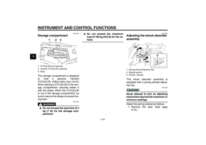
To install the seat
1. Insert the projection on the front of
the seat into the seat holder as
shown.2. Push the rear of the seat down to
lock it in place.
3. Remove the key.
NOTE:Make sure that the seat is properly se-cured before riding.
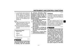
EAU14281
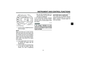
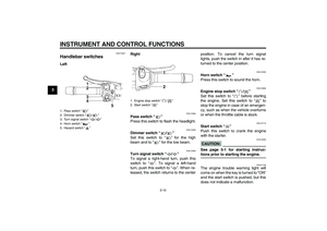
Helmet holder To open the helmet holder, insert the
key into the lock, and then turn the key
as shown.
To lock the helmet holder, place it in the
original position, and then remove the
key.
WARNING
EWA10160
Never ride with a helmet attached to
the helmet holder, since the helmet
may hit objects, causing loss of con-trol and possibly an accident.
1. Seat lock
2. Unlock.
1. Projection
2. Seat holder
1. Helmet holder
2. Unlock.
U1B3E3E0.book Page 15 Friday, July 14, 2006 11:34 AM
Page 30 of 94

When placing a CYCLELOK in the s")
INSTRUMENT AND CONTROL FUNCTIONS
3-16
3
EAU14422
Storage compartment This storage compartment is designed
to hold a genuine Yamaha
CYCLELOK. (Other locks may not fit.)
When placing a CYCLELOK in the stor-
age compartment, securely fasten it
with the straps. When the CYCLELOK
is not in the storage compartment, be
sure to secure the straps to prevent los-
ing them.
WARNING
EWA10961
�
Do not exceed the load limit of 3
kg (7 lb) for the storage com-
partment.
�
Do not exceed the maximum
load of 196 kg (432 lb) for the ve-hicle.
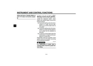
EAU36462
Adjusting the shock absorber
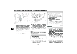
assembly This shock absorber assembly is
equipped with a spring preload adjust-
ing ring.CAUTION:
ECA10100
Never attempt to turn an adjusting
mechanism beyond the maximum orminimum settings.
Adjust the spring preload as follows.
1. Remove the seat. (See page
3-15.)
1. CYCLELOK bar (optional)
2. Yamaha CYCLELOK (optional)
3. Strap
1. Spring preload adjusting ring
2. Special wrench
3. Position indicator
U1B3E3E0.book Page 16 Friday, July 14, 2006 11:34 AM
Page 31 of 94
. To decrease the spring pre-
load and thereby soft")
INSTRUMENT AND CONTROL FUNCTIONS
3-17
3 2. To increase the spring preload and
thereby harden the suspension,
turn the adjusting ring in direction
(a). To decrease the spring pre-
load and thereby soften the sus-
pension, turn the adjusting ring in
direction (b).
NOTE:�
Align the appropriate notch in the
adjusting ring with the position in-
dicator on the shock absorber.
�
Use the special wrench included in
the owner’s tool kit to make the ad-justment.
3. Install the seat.WARNING
EWA10220
This shock absorber contains highly
pressurized nitrogen gas. For prop-
er handling, read and understandthe following information before
handling the shock absorber. The
manufacturer cannot be held re-
sponsible for property damage or
personal injury that may result from
improper handling.
�
Do not tamper with or attempt to
open the gas cylinder.
�
Do not subject the shock ab-
sorber to an open flame or other
high heat sources, otherwise it
may explode due to excessive
gas pressure.
�
Do not deform or damage the
gas cylinder in any way, as this
will result in poor damping per-
formance.
�
Always have a Yamaha dealerservice the shock absorber.
EAU15301
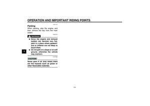
Sidestand The sidestand is located on the left side
of the frame. Raise the sidestand or
lower it with your foot while holding the
vehicle upright.NOTE:The built-in sidestand switch is part of
the ignition circuit cut-off system, which
cuts the ignition in certain situations.
(See further down for an explanation ofthe ignition circuit cut-off system.)
WARNING
EWA10240
The vehicle must not be ridden with
the sidestand down, or if the side-
stand cannot be properly moved up
(or does not stay up), otherwise the
sidestand could contact the ground
and distract the operator, resulting
in a possible loss of control.
Yamaha’s ignition circuit cut-off
system has been designed to assist
the operator in fulfilling the respon-
sibility of raising the sidestand be-
fore starting off. Therefore, check
this system regularly as described
Spring preload setting:
Minimum (soft):
1
Standard:
3
Maximum (hard):
7
U1B3E3E0.book Page 17 Friday, July 14, 2006 11:34 AM
Page 32 of 94
INSTRUMENT AND CONTROL FUNCTIONS
3-18
3below and have a Yamaha dealer re-
pair it if it does not function proper-
ly.
EAU15311
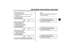
Ignition circuit cut-off system The ignition circuit cut-off system (com-
prising the sidestand switch, clutch
switch and neutral switch) has the fol-
lowing functions.�
It prevents starting when the trans-
mission is in gear and the side-
stand is up, but the clutch lever is
not pulled.
�
It prevents starting when the trans-
mission is in gear and the clutch le-
ver is pulled, but the sidestand is
still down.
�
It cuts the running engine when the
transmission is in gear and the sid-
estand is moved down.
Periodically check the operation of the
ignition circuit cut-off system according
to the following procedure.WARNING
EWA10250
If a malfunction is noted, have a
Yamaha dealer check the system be-fore riding.
U1B3E3E0.book Page 18 Friday, July 14, 2006 11:34 AM