Page 68 of 100

PERIODIC MAINTENANCE AND MINOR REPAIR
6-14
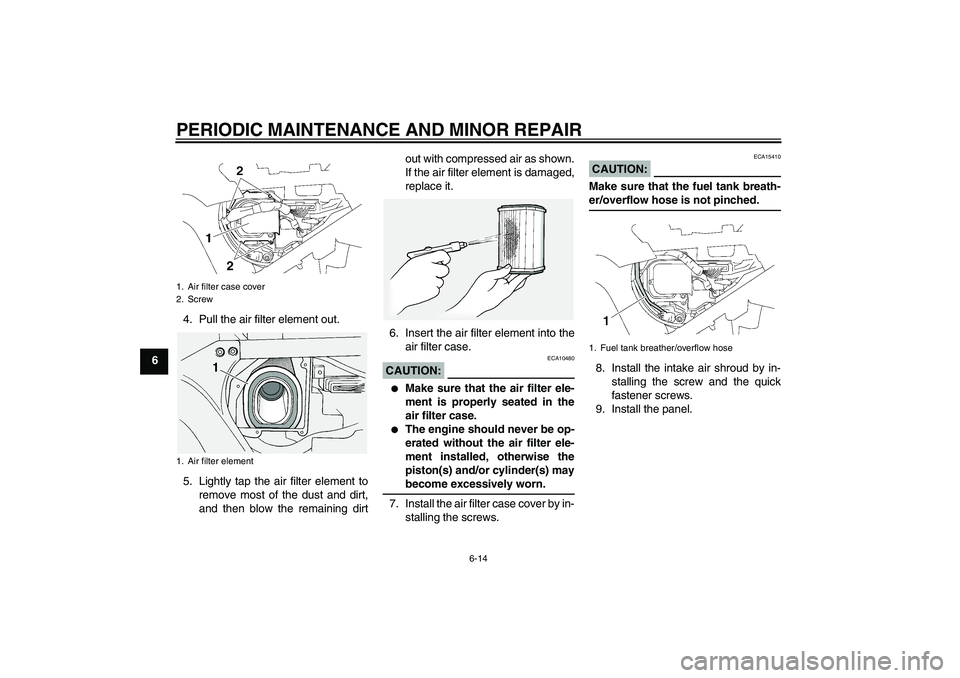
64. Pull the air filter element out.
5. Lightly tap the air filter element to
remove most of the dust and dirt,
and then blow the remaining dirtout with compressed air as shown.
If the air filter element is damaged,
replace it.
6. Insert the air filter element into the
air filter case.
CAUTION:
ECA10480
�
Make sure that the air filter ele-
ment is properly seated in the
air filter case.
�
The engine should never be op-
erated without the air filter ele-
ment installed, otherwise the
piston(s) and/or cylinder(s) maybecome excessively worn.
7. Install the air filter case cover by in-
stalling the screws.
CAUTION:
ECA15410
Make sure that the fuel tank breath-er/overflow hose is not pinched.
8. Install the intake air shroud by in-
stalling the screw and the quick
fastener screws.
9. Install the panel.
1. Air filter case cover
2. Screw
1. Air filter element
1. Fuel tank breather/overflow hose
U3P6E1E0.book Page 14 Thursday, October 5, 2006 10:13 AM
Page 73 of 100

PERIODIC MAINTENANCE AND MINOR REPAIR
6-19
6
EAU22072
Clutch lever Since this model is equipped with a hy-
draulic clutch, adjusting the clutch lever
free play is not needed. However, it is
necessary to check the clutch fluid level
and check the hydraulic system for
leakage before each ride. If the clutch
lever free play does become excessive,
and shifting becomes rough or clutch
slippage occurs, causing poor acceler-
ation, there may be air in the clutch sys-
tem. If there is air in the hydraulic
system, have a Yamaha dealer bleed
the system before operating the motor-
cycle.
EAU36501
Rear brake light switch The rear brake light switch, which is ac-
tivated by the brake pedal, is properly
adjusted when the brake light comes
on just before braking takes effect. If
necessary, have a Yamaha dealer ad-
just the brake light switch.
EAU22390
Checking the front and rear
brake pads The front and rear brake pads must be
checked for wear at the intervals spec-
ified in the periodic maintenance and
lubrication chart.
EAU22420
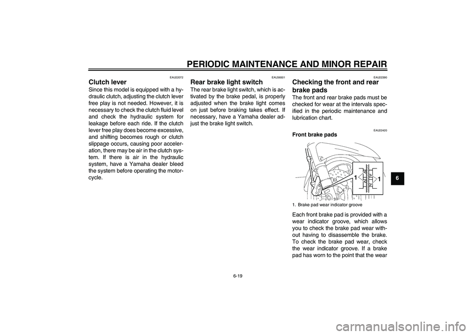
Front brake pads
Each front brake pad is provided with a
wear indicator groove, which allows
you to check the brake pad wear with-
out having to disassemble the brake.
To check the brake pad wear, check
the wear indicator groove. If a brake
pad has worn to the point that the wear1. Brake pad wear indicator groove
U3P6E1E0.book Page 19 Thursday, October 5, 2006 10:13 AM
Page 82 of 100

PERIODIC MAINTENANCE AND MINOR REPAIR
6-28
6
EAU23657
Replacing the fuses The main fuse, the fuse boxes and the
ABS motor fuse are located under pan-
el A. (See page 6-5.)
If a fuse is blown, replace it as follows.
1. Turn the key to “OFF” and turn off
the electrical circuit in question.
2. Remove the blown fuse, and then
install a new fuse of the specified
amperage.
CAUTION:
ECA10640
Do not use a fuse of a higher amper-
age rating than recommended to
avoid causing extensive damage to
the electrical system and possibly afire.
1. Main fuse
2. Fuse box
3. ABS motor fuse
4. ABS motor spare fuse
1. Fuse box
2. Right radiator fan fuse
3. Left radiator fan fuse
4. Hazard fuse
5. Backup fuse (for odometer, clock and immo-
bilizer system)
6. Headlight fuse
7. Signaling system fuse
8. ABS control unit fuse
9. Ignition fuse
10.Fuel injection system fuse
11.Auxiliary DC jack fuse
12.Spare fuse
Specified fuses:
Main fuse:
50.0 A
Headlight fuse:
25.0 A
Signaling system fuse:
15.0 A
Ignition fuse:
10.0 A
Radiator fan fuse:
15.0 A × 2
Backup fuse:
10.0 A
Hazard fuse:
10.0 A
Fuel injection system fuse:
15.0 A
ABS control unit fuse:
10.0 A
Auxiliary DC jack fuse:
3.0 A
ABS motor fuse:
30.0 A
U3P6E1E0.book Page 28 Thursday, October 5, 2006 10:13 AM
Page 83 of 100
PERIODIC MAINTENANCE AND MINOR REPAIR
6-29
6 3. Turn the key to “ON” and turn on
the electrical circuit in question to
check if the device operates.
4. If the fuse immediately blows
again, have a Yamaha dealer
check the electrical system.
EAU40360
Headlight bulb If a headlight does not come on, have a
Yamaha dealer check its electrical cir-
cuit or replace the bulb.
EAU39880
Front turn signal light If a front turn signal light does not come
on, have a Yamaha dealer check its
electrical circuit or replace the bulb.
U3P6E1E0.book Page 29 Thursday, October 5, 2006 10:13 AM
Page 84 of 100
PERIODIC MAINTENANCE AND MINOR REPAIR
6-30
6
EAU27001
Replacing a rear turn signal
light bulb or a tail/brake light
bulb 1. Remove the passenger seat. (See
page 3-20.)
2. Remove the socket (together with
the bulb) by turning it counter-
clockwise.
3. Remove the defective bulb by
pushing it in and turning it counter-
clockwise.
4. Insert a new bulb into the socket,
push it in, and then turn it clock-
wise until it stops.
5. Install the socket (together with the
bulb) by turning it clockwise.6. Install the passenger seat.
EAU24310
Replacing the license plate
light bulb 1. Remove the license plate light unit
by removing the screws.
2. Remove the socket (together with
the bulb) by pulling it out.
1. Turn signal light bulb socket
2. Tail/brake light bulb socket
1. Screw
2. License plate light unit
1. License plate light bulb
U3P6E1E0.book Page 30 Thursday, October 5, 2006 10:13 AM
Page 85 of 100

PERIODIC MAINTENANCE AND MINOR REPAIR
6-31
6 3. Remove the defective bulb by pull-
ing it out.
4. Insert a new bulb into the socket.
5. Install the socket (together with the
bulb) by pushing it in.
6. Install the license plate light unit by
installing the screws.
EAU39020
Auxiliary light bulb If the auxiliary light does not come on,
have a Yamaha dealer check the elec-
trical circuit or replace the bulb.
EAU25870
Troubleshooting Although Yamaha motorcycles receive
a thorough inspection before shipment
from the factory, trouble may occur dur-
ing operation. Any problem in the fuel,
compression, or ignition systems, for
example, can cause poor starting and
loss of power.
The following troubleshooting charts
represent quick and easy procedures
for checking these vital systems your-
self. However, should your motorcycle
require any repair, take it to a Yamaha
dealer, whose skilled technicians have
the necessary tools, experience, and
know-how to service the motorcycle
properly.
Use only genuine Yamaha replace-
ment parts. Imitation parts may look like
Yamaha parts, but they are often inferi-
or, have a shorter service life and can
lead to expensive repair bills.
U3P6E1E0.book Page 31 Thursday, October 5, 2006 10:13 AM
Page 89 of 100

MOTORCYCLE CARE AND STORAGE
7-2
7 thinner, fuel (gasoline), rust re-
movers or inhibitors, brake flu-
id, antifreeze or electrolyte.
�
Do not use high-pressure wash-
ers or steam-jet cleaners since
they cause water seepage and
deterioration in the following ar-
eas: seals (of wheel and swing-
arm bearings, fork and brakes),
electric components (couplers,
connectors, instruments,
switches and lights), breather
hoses and vents.
�
For motorcycles equipped with
a windshield: Do not use strong
cleaners or hard sponges as
they will cause dulling or
scratching. Some cleaning com-
pounds for plastic may leave
scratches on the windshield.
Test the product on a small hid-
den part of the windshield to
make sure that it does not leave
any marks. If the windshield is
scratched, use a quality plastic
polishing compound afterwashing.After normal use
Remove dirt with warm water, a mild
detergent, and a soft, clean sponge,
and then rinse thoroughly with clean
water. Use a toothbrush or bottlebrush
for hard-to-reach areas. Stubborn dirt
and insects will come off more easily if
the area is covered with a wet cloth for
a few minutes before cleaning.
After riding in the rain, near the sea oron salt-sprayed roadsSince sea salt or salt sprayed on roads
during winter are extremely corrosive in
combination with water, carry out the
following steps after each ride in the
rain, near the sea or on salt-sprayed
roads.NOTE:Salt sprayed on roads in the winter mayremain well into spring.
1. Clean the motorcycle with cold wa-
ter and a mild detergent, after the
engine has cooled down.
CAUTION:
ECA10790
Do not use warm water since it in-
creases the corrosive action of thesalt.
2. After drying the motorcycle, apply
a corrosion protection spray on all
metal, including chrome- and nick-
el-plated, surfaces to prevent cor-
rosion.
After cleaning
1. Dry the motorcycle with a chamois
or an absorbing cloth.
2. Use a chrome polish to shine
chrome, aluminum and stainless-
steel parts, including the exhaust
system. (Even the thermally in-
duced discoloring of stainless-
steel exhaust systems can be re-
moved through polishing.)
3. To prevent corrosion, it is recom-
mended to apply a corrosion pro-
tection spray on all metal,
including chrome- and nickel-plat-
ed, surfaces.
4. Use spray oil as a universal clean-
er to remove any remaining dirt.
U3P6E1E0.book Page 2 Thursday, October 5, 2006 10:13 AM
Page 94 of 100
SPECIFICATIONS
8-3
8
Voltage, capacity:
12 V, 12.0 AhHeadlight:Bulb type:
Halogen bulbBulb voltage, wattage × quantity:Headlight:
12 V, 60 W/55.0 W × 2
Tail/brake light:
12 V, 5.0 W/21.0 W × 2
Front turn signal light:
12 V, 21.0 W × 2
Rear turn signal light:
12 V, 21.0 W × 2
Auxiliary light:
12 V, 5.0 W × 2
License plate light:
12 V, 5.0 W × 1
Meter lighting:
LED
Neutral indicator light:
LED
High beam indicator light:
LED
Oil level warning light:
LED
Turn signal indicator light:
LED
Engine trouble warning light:
LED
ABS warning light:
LED
Immobilizer system indicator light:
LED
Fuses:Main fuse:
50.0 A
Headlight fuse:
25.0 A
Signaling system fuse:
15.0 A
Ignition fuse:
10.0 A
Radiator fan fuse:
15.0 A × 2
Hazard fuse:
10.0 A
Fuel injection system fuse:
15.0 A
ABS control unit fuse:
10.0 A
ABS motor fuse:
30.0 A
Auxiliary DC jack fuse:
3.0 A
Backup fuse:
10.0 A
U3P6E1E0.book Page 3 Thursday, October 5, 2006 10:13 AM