Page 36 of 140
4-14
1
2
34
5
6
7
8
9
10
11
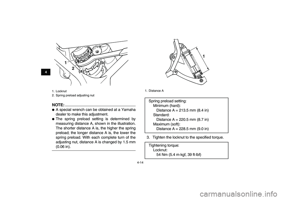
NOTE:
�
A special wrench can be obtained at a Yamaha
dealer to make this adjustment.
�
The spring preload setting is determined by
measuring distance A, shown in the illustration.
The shorter distance A is, the higher the spring
preload; the longer distance A is, the lower the
spring preload. With each complete turn of the
adjusting nut, distance A is changed by 1.5 mm
(0.06 in).3. Tighten the locknut to the specified torque.
1. Locknut
2. Spring preload adjusting nut
1
2
(a)(b)
1. Distance A
Spring preload setting:
Minimum (hard):
Distance A = 213.5 mm (8.4 in)
Standard:
Distance A = 220.5 mm (8.7 in)
Maximum (soft):
Distance A = 228.5 mm (9.0 in)
Tightening torque:
Locknut:
54 Nm (5.4 m·kgf, 39 ft·lbf)
1
Page 37 of 140
4-15
1
2
34
5
6
7
8
9
10
11
CAUTION:
ECB00080
Always tighten the locknut against the adjust-
ing nut, and then tighten it to the specified
torque.
Rebound damping force
Turn the adjusting dial in direction (a) to increase
the rebound damping force and thereby harden
the damping, and in direction (b) to decrease the
rebound damping force and thereby soften the
damping.
Compression damping force
Turn the adjusting knob in direction (a) to increase
the compression damping force and thereby hard-
en the damping, and in direction (b) to decrease
the compression damping force and thereby soft-
en the damping.
1. Rebound damping force adjusting dial
1(a) (b)
Rebound damping setting:
Minimum (soft):
20 click(s) in direction (b)*
Standard:
12 click(s) in direction (b)*
Maximum (hard):
3 click(s) in direction (b)*
* With the adjusting dial fully turned in direc-
tion (a)
Page 78 of 140
8-2
1
2
3
4
5
6
78
9
10
11
The service information included in this manual
and the tools provided in the owner’s tool kit are in-
tended to assist you in the performance of preven-
tive maintenance and minor repairs. However,
additional tools such as a torque wrench may be
necessary to perform certain maintenance work
correctly.
NOTE:
If you do not have the tools or experience required
for a particular job, have a Yamaha dealer perform
it for you.
WARNING
EWB01850
Never modify this ATV through improper in-
stallation or use of accessories, as it may
cause changes in handling, which in some sit-
uations could lead to an accident. All parts and
accessories added to this ATV should be gen-
uine Yamaha or equivalent components de-
signed for use on this ATV and should be
installed and used according to instructions. If
you have questions, consult an authorized
Yamaha ATV dealer.
Page 84 of 140
8-8
1
2
3
4
5
6
78
9
10
11
stead, have a Yamaha dealer check the ATV.
3. Check each spark plug for electrode erosion
and excessive carbon or other deposits, and
replace it if necessary.
To install a spark plug
1. Measure the spark plug gap with a wire thick-
ness gauge and, if necessary, adjust the gap
to specification.
2. Clean the surface of the spark plug gasket
and its mating surface, and then wipe off any
grime from the spark plug threads.
3. Install the spark plug with the spark plug
wrench, and then tighten it to the specified
torque.NOTE:
If a torque wrench is not available when installing Specified spark plug:
NGK/BR8ES
Spark plug gap:
0.7–0.8 mm (0.028–0.031 in)
1. Spark plug gap
Tightening torque:
Spark plug:
20 Nm (2.0 m·kgf, 14 ft·lbf)
Page 85 of 140

8-9
1
2
3
4
5
6
78
9
10
11
a spark plug, a good estimate of the correct torque
is 1/4–1/2 turn past finger tight. However, the spark
plug should be tightened to the specified torque as
soon as possible.
4. Install the spark plug cap.
EBU23341
Transmission oil
The transmission oil level should be checked be-
fore each ride. In addition, the transmission oil
must be changed at the intervals specified in the
periodic maintenance and lubrication chart.
To check the transmission oil level
1. Place the ATV on a level surface.
2. Start the engine, warm it up for several min-
utes, and then turn it off.
3. Wait a few minutes until the oil settles, remove
the oil filler cap, wipe the dipstick off with a
clean rag, insert it back into the oil filler hole
(without screwing it in), and then remove it
again to check the oil level.NOTE:
The transmission oil should be between the mini-
mum and maximum level marks.
4. If the oil is at or below the minimum level mark,
add sufficient oil of the recommended type to
raise it to the correct level.
5. Insert the dipstick into the oil filler hole, and
then tighten the oil filler cap.
To change the transmission oil
1. Place the ATV on a level surface.
1. Dipstick
2. Maximum level mark
3. Minimum level mark
12
3
Page 86 of 140

8-10
1
2
3
4
5
6
78
9
10
11
2. Start the engine, warm it up for several min-
utes, and then turn it off.
3. Place an oil pan under the transmission to col-
lect the used oil.
4. Remove the oil filler cap and the drain bolt to
drain the oil from the transmission.
5. Install the drain bolt, and then tighten it to the
specified torque.6. Add the specified amount of the recommend-
ed transmission oil, and then install and tight-
en the oil filler cap.
CAUTION:
ECB00430
�
In order to prevent clutch slippage (since the
transmission oil also lubricates the clutch),
do not mix any chemical additives. Do not
use oils with a diesel specification of “CD” or
oils of a higher quality than specified. In ad-
dition, do not use oils labeled “ENERGY
CONSERVING II” or higher.
�
Make sure that no foreign material enters the
crankcase.
7. Start the engine, and then let it idle for several
minutes while checking the transmission for
oil leakage. If oil is leaking, immediately turn
the engine off and check for the cause.
8. Turn the engine off, and then check the oil lev-
el and correct it if necessary.
1. Transmission oil drain bolt
Tightening torque:
Transmission oil drain bolt:
20 Nm (2.0 m·kgf, 14 ft·lbf)
1
Recommended transmission oil:
See page 10-1.
Oil quantity:
1.5 L (1.59 US qt) (1.32 Imp.qt)
Page 91 of 140

8-15
1
2
3
4
5
6
78
9
10
11
7. After draining the coolant, thoroughly flush the
cooling system with clean tap water.
8. Replace the coolant drain bolt washers if they
are damaged, and then tighten the coolant
drain bolts to the specified torque.
9. Connect the coolant reservoir hose.
10. Pour the recommended coolant into the reser-voir to the maximum level mark, and then in-
stall the reservoir cap.
11. Pour the recommended coolant into the radia-
tor until it is full.
CAUTION:
ECB00401
�
If coolant is not available, use distilled water
or soft tap water instead. Do not use hard wa-
ter or salt water since it is harmful to the en-
gine.
�
If water has been used instead of coolant, re-
place it with coolant as soon as possible,
otherwise the cooling system will not be pro-
1. Coolant reservoir hose
2. Coolant reservoir
Tightening torque:
Coolant drain bolt:
10 Nm (1.0 m·kgf, 7 ft·lbf)
1
2
Antifreeze/water mixture ratio:
1:1
Recommended antifreeze:
High-quality ethylene glycol antifreeze con-
taining corrosion inhibitors for aluminum en-
gines
Coolant quantity:
Radiator capacity (including all routes):
1.50 L (1.59 US qt) (1.32 Imp.qt)
Coolant reservoir capacity (up to the maxi-
mum level mark):
0.28 L (0.30 US qt) (0.25 Imp.qt)
Page 103 of 140

8-27
1
2
3
4
5
6
78
9
10
11
Assembling and installing the carburetors
Assemble and install both carburetors by the fol-
lowing steps.
1. Install the needle valve and float.
2. Install the float chamber by installing the
screws.
3. Install the carburetor and tighten the joint
screws.
4. Assemble the throttle valve.
5. Install the mixing chamber cap, and then tight-
en it securely to the specified torque.
6. Install the mixing chamber cap securing plate
by installing the screw.CAUTION:
ECB00501
Be sure to match one of the projections on the
carburetor cap with one of the slots on the se-
curing plate. If the securing plate does not
match a projection, tighten the carburetor cap
until they align. Do not loosen the carburetor
cap.
7. Tighten the mixing chamber cap securing
plate screw to the specified torque.
8. Tighten the carburetor joint screws.
Adjusting the throttle cables
1. Move the throttle lever a few times. Tightening torque:
Mixing chamber cap:
4 Nm (0.4 m·kgf, 2.9 ft·lbf)
1. Mixing chamber cap securing plate
2. Projection
3. Slot
4. Screw
Tightening torque:
Mixing chamber cap securing plate screw:
3.5 Nm (0.35 m·kgf, 2.5 ft·lbf)
12
3
4