2007 VOLKSWAGEN GOLF PLUS connector
[x] Cancel search: connectorPage 117 of 541
Securing the
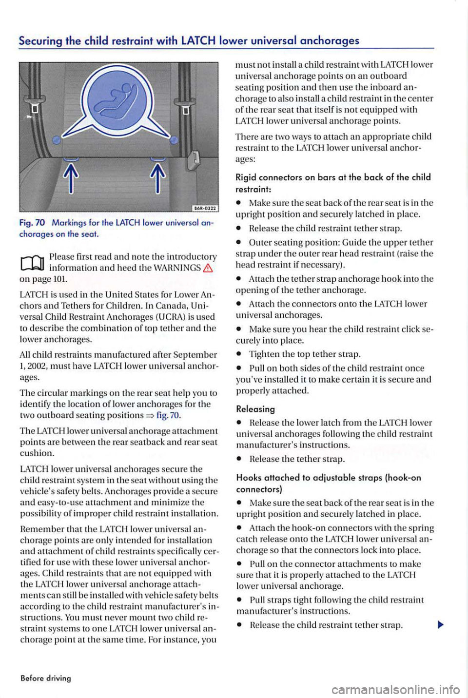
Markings for the LATCH lower universal choroges on the
firs t read and no te th e introducto ry inform ation heed th e W ARN INGS on page
In is used
to describe the combination of top tethe r a nd the
lower anc h ora ges .
All must have LATC H l ower universa l
fig.
restraint sys te m in the seat w ith out usi ng the
ve hicle's safety b elt s. Anch o rages prov ide a secure
a nd easy-to- use attachment a nd minimize the possib ility o f improper chil d restraint installa tio n.
R e m em
ber that the LAT C H lower u niversa l
restraint s specifically tifi ed for use w ith these lower unive rsal
mentscan still b e in stalle d w ith vehicl e safe ty belt s accord in g to t he c hild restraint manufa cturer's stru ctio ns. straint syste m s to one LA T C H lowe r universa l chorage point at the sam e tim e. For in sta nce, you
Before driving
must not in stall a child restraint with LA T C H lower unive rsal a n chorage p oints on a n outboard seatin g posi tion and then use the inboard ch o rage to also install a c hild restraint in the cente r
o f th e rea r seat that itself is no t equipped with LATC H lower unive rs al anchorage point s.
There are two ways to a ttach an approp riate restraint to the LATCH lower unive rsa l
Make sure the seat back oft h e rear seat i s in the upright positi on and securely latc h ed in place.
Hele ase th e c hild res tra int tethe r strap.
O uter seating positi on : G uid e th e upper t ether strap under the outer rear head res traint (raise the
h ead restra int if necessary) .
Attach the tether strap an ch o rage hook int o th e openin g of the tether anc h o rage.
Attach the connecto rs onto the LAT C H lower unive rsal a n ch o rages.
Ma ke sure you hear the restr aint click curely into p lace.
Ti ghten the top te th er stra p.
o n both si des of the c hild restraint once yo u've installed it to m ake certain it is secure a nd
p roperly auach ed.
Releasing
Helease the lower l atch from the LATC H lower
uni versa l a nchorages followin g the c hild restra int
m anufacturer's instru ctions.
Release the tethe r strap.
Hooks
attached to adjustable strops {hook-on
connectors)
Ma ke sure the seat back oft h e rea r seat is in the
u pright positi on and securely la tc h ed in place.
connecto rs w ith th e spring catc h re lease onto the LATCH lower universa l cho rage so that the connectors lock into p lace.
straps tight fo llo win g the c hild restrai nt
m an ufacture r's in str u ction s.
nele ase the child restraint tet he r stra p.
Page 118 of 541
seating position: Guide the upper te th er
s trap under th e o uter r ear head restra int (raise th e
h ead restra int if n ecessary).
Guide th e te th er strap betwe en th e re ar seat back and the lu ggage compartment cove r.
A ttach th e tether s trap an chorage hoo k
After you have install ed th e c hild seat, pull on bot h of t he adju stabl e strap s o n th e child sca t and p ull also on th e te th er strap to m ake certain the seat is sec ure an d prop erly attac hed.
R e le asing
L oose n th e te nsion o n th e strap followin g the chi ld re straint manufa ctu re r's in structio ns.
De press th e s pring ca tc h on th e hook.
tio n.
Move the hoo k in the dir ection of the vehicle floor so th at th ere is e no ugh sp ace to release the connector from the lo wer a n chora ge.
Release the teth er strap.
You must take sp ecia l preca utions w he n in sta lling
a child res traint w ith the vehicle safety belt or with
w ays route th e unuse d ce nt er scat s afe ty belt and th e unused safety belt for th e seatin g posit io n
w here the child restraint is be in g in stalle d
around th e rear h ead restrain! behind the c hild stra int to help preve nt a chil d from play ing w ith
th e unused b elt and beco min g e ntan gled in it.
Improper use of the sys tem can increase th e risk of serio us person a l inju ry and death in an accid ent.
Alway s care fully fo ll ow the child re straint manufacture r's in structions for proper
vers al anchorages or safety belts in your ve hicl e.
Never mount two lower unive rsal a nchorage point.
These anchors w ere developed only for c hild seats using th e sys tem.
Neve r attach other ch ild seats, be lts, lugg age or other thin gs to the anchorages.
Alway s make s ure that you hear a
the seat is not secure and co uld fly fo rward
and hit the interior of th e ve hicl e or be ejected from the ve hicle.
Be careful not to activa te th e sw itchab le
pull the
safety belt out fa r en o ugh to allow you to route th e
b el t around th e hea d restrai nt.
116 117
Page 155 of 541
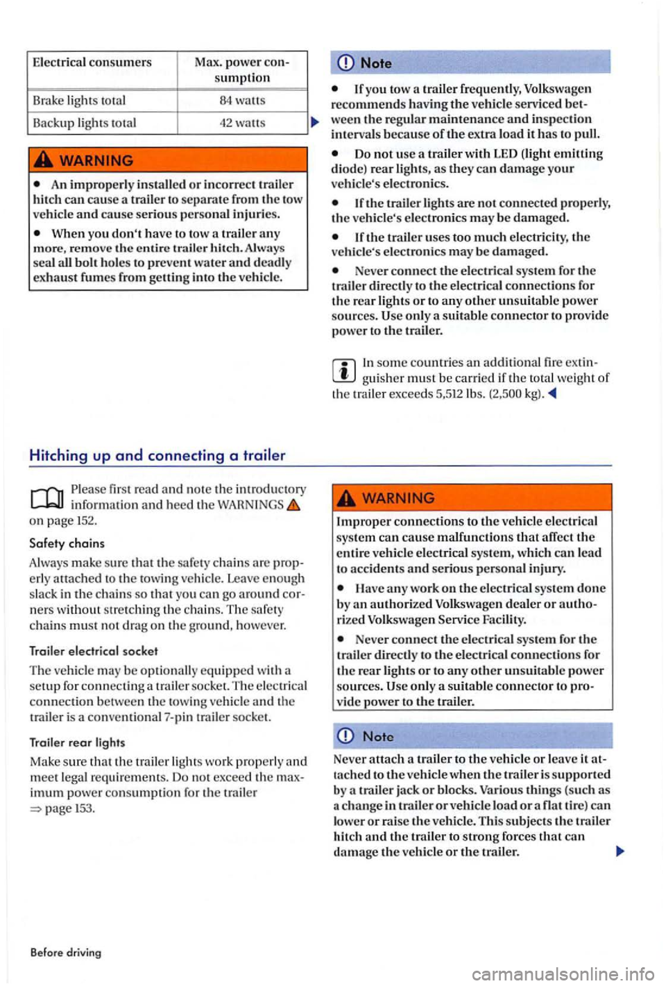
Electrical consumers Max. power sumption
Brake lights total
An improp erl y in sta ll ed or incorrect t railer hit ch can
trail er any
m ore , remove the entire trailer hitch. Always
sea l all bolt ho les to prevent water and deadly
exhaust fumes from getting int o the ve hicle.
Hitching up and connecting a
Ple a se firs t r ea d and no te the introdu cto ry informati on and heed th e on pag e 152.
n ers witho ut str etc hi ng the c hain s. T he safety
c hain s mu st n ot drag o n th e g ro und, ho wev er.
Trailer electrical socket
The vehicl e m ay be opti onally equipped with a
setup for con nec ting a trailer so cket. Th e ele ctrical connec tio n betwee n th e towing ve hicle and the
trailer is a convent io nal7-pin trailer socke t.
T raile r rear lights
Mak e sure that th e trailer light s work prop erly and
m ee t le gal re quir em ent s. D o no t excee d th e
im um po w er co nsumpti on f or th e trail er 153 .
Before drivin g
Note
If you tow a trailerfrequenll y,
ween th e re gular maintenance and inspecti on
int erva ls because of the extra load it has to pull.
Do not use a trailer with LED (lig ht emitting
di ode) rear lights, as they ca n d amage your ve hicle's ele ctroni cs.
If the uses too much elec tricity, the
ve hicle' s e lectroni cs may be damaged.
Never connect the electric.1.l system for th e
trailer directly to the electrical connection s for
th e rear light s or to any other unsuitabl e powe r
sources. Use onl y a suit abl e connector to provide
po we r to trailer.
In some co untries an additio na l fire extingui sh er must be carried if th e tota l w eight of th e trailer exce e d s 5,512lb s.
Improp er connections to the ve hicl e elec trical
sys te m can cause malfunction s that affect the
entire vehicle electrical system, which lead to acciden ts and seriou s pe rso nal injury.
Have any work on the electrical syste m d on e
b y an authorized Volkswage n dealer or autho
rized Volk sw age n Facility.
Never connect th e e lectrical syste m for the trailer to Ll1e e lectrical connections for
th e rear lights or to any other unsuit abl e power
sources . Usc only a suitabl e con nec tor to vide power to the trail er .
Note
------------------------~ Never attach trailer to the vehicle or leave it taclled to the vehicle when the trail er i s supported
b y a trailer jack or blocks. Various thin gs (sucl1 as c h a ng e in traile r or vehicl e load or a fla t tir e) can lower or raise the ve hicle. Thi s subj ects th e trailer
hit ch and th e trailer to strong fo rces that can d a mag e th e ve hicl e or the trailer.
Page 305 of 541
Using a when it is not connected to the
firs t n ote the imroductory
informati on and h eed the on page303.
Mob
ile or cellul ar t eleph o nes send receive
rad io waves, sometimes called "radiofr eque ncy
e ne rgy" (RF en ergy). bo th when they be ing
u se d when they in stand-b y mode. scie nt ific literature indi cates that radio
tablish ed b y authoriti es and commiuees in an efT to keep the troma gnetic radiati on from leve ls that not cause proble m s. ever , th ere is no sc ie mifi cally ba sed proof that
w ireles s phones arc absolut ely safe.
Therefore some ex pert s recomm end a tionary approach regarding the use of cellular phones by taking meas ures low er th e sonal exposure to elec tromagnetic fields. usin g a cellular te lepho ne in sid e m otor ve hicle
without proper connectio n to an integrat ed h icle te lephone antenna, your p erso nal exposure
to elec tromagn eti c fie ld s be highe r than whe n
u sing th e necte d to an or o th er o ut sid e vehicle
t e leph o ne a ntenna.
Y o
ur ve hicl e may be equipp ed w ith an optio nal hands-free sys te m that will permit many or th e
features o f a compatibl e Blueto oth ® enabled
ni ence and is consis te nt with the laws or an and lo ca litie s that hibit the use of te lephones with out som e
kind or hands -free dev ice.
The hands- free system in your vehicl e ca n be used with certain cell phones th at arc connecte d b y
w ire and hard ware connector or via compatibl e
B luetooth® -enabl ed pho nes with cradle that is
designed to your
times. the phone
in its cradle permit s it t o be charged. but more portantly conn ec ts th e cellular phone to the hicle's outsid e A
low er your p erso nal exposure to e lec tromagnetic fie ld s. You
n o t be co nnected to th e ve hicle's
rien ce more dropped
on a bas e plate on the instrument panel. Because of the large numbe r and variet y of cellular
tel eph ones on th e mark et and the frequ ency with
w hi ch new models are int roduced, Volkswage n does not ofTer c radle s for cellular te leph ones. of the ce llular
t e lephone that you plan to use.
A cell pho ne on th e scat, instrument panel or in other p laces can be th row n around th e inside of the ve hicl e during sudden braking maneuver,
cupants.
Neve r plac e or altach accessories or other objects (such as cup holders, telephone brackets, note pads, navigat ion systems, large,
h eavy or b ulky objects) on the doors, on th e
winds h ie ld, over or near th e area marked
pant. Such object s could cause se rious injury in a collisio n, especially when the a.irbags
Using a cell phone or radio inside th e ve hicle without separate side antenna can be dangerou s to your health and that or your passengers because the magnetic radiation e nergy that cell phones and rad io s emit may be above establi shed li m its.
T hi s also applies if th e out side antenna is not properly.
Always keep the cell phone antenna at least 8 inches
th e way pacemakers work.
Page 343 of 541
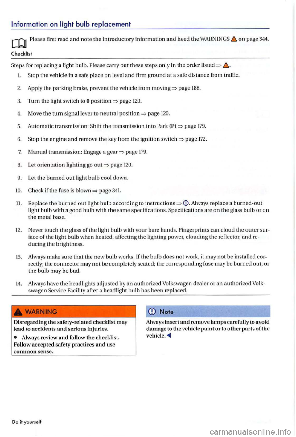
Please first read and note the introdu cto ry information and heed the on page 344.
for re pla cing a light bulb. Please carry out these ste p s only in the order
page 188.
3. Turn the light switch page
4. Move the tu rn signal lever to neutral page
5. Auto mati c transmission: 179.
6. the eng ine and re move the key from the ig ni tion page 172.
7. Manu al transmission: Engage a page 179.
8. Let orie nt ation lighting go page
9. Let the burned out light bulb cool down.
page 341.
11. R e place the burned out light bulb accordi ng Always replace a burned-out light bulb with a good bulb with the sa me s pecifications. Specifications are on the g lass bulb or on
the meta l base.
12. Neve r tou ch the glass of th e light bulb with your bare hands. Finge rprin ts can clo ud t he o uter sur
f ace of the light bulb when heated, affec ting the lighting power, clouding the reflector, andre
d u ci ng th e brightness.
13. Always make sure th at the new bulb works. the bulb does not work, it may not be installed cor
rectly; the connector may no t be co mplet ely seated; the correspondin g fuse may be burned out; or the bulb may be bad.
14. Always have th e headligh ts adj usted by an authorized Vol k swage n dealer or an a uth orized swagen Service Facility
to accidents and serious Injuries.
Always review and follow the
Note
Alway s insert and remove lamps car efully to avoid damage to the vehicle paint or to other parts of the
Page 345 of 541
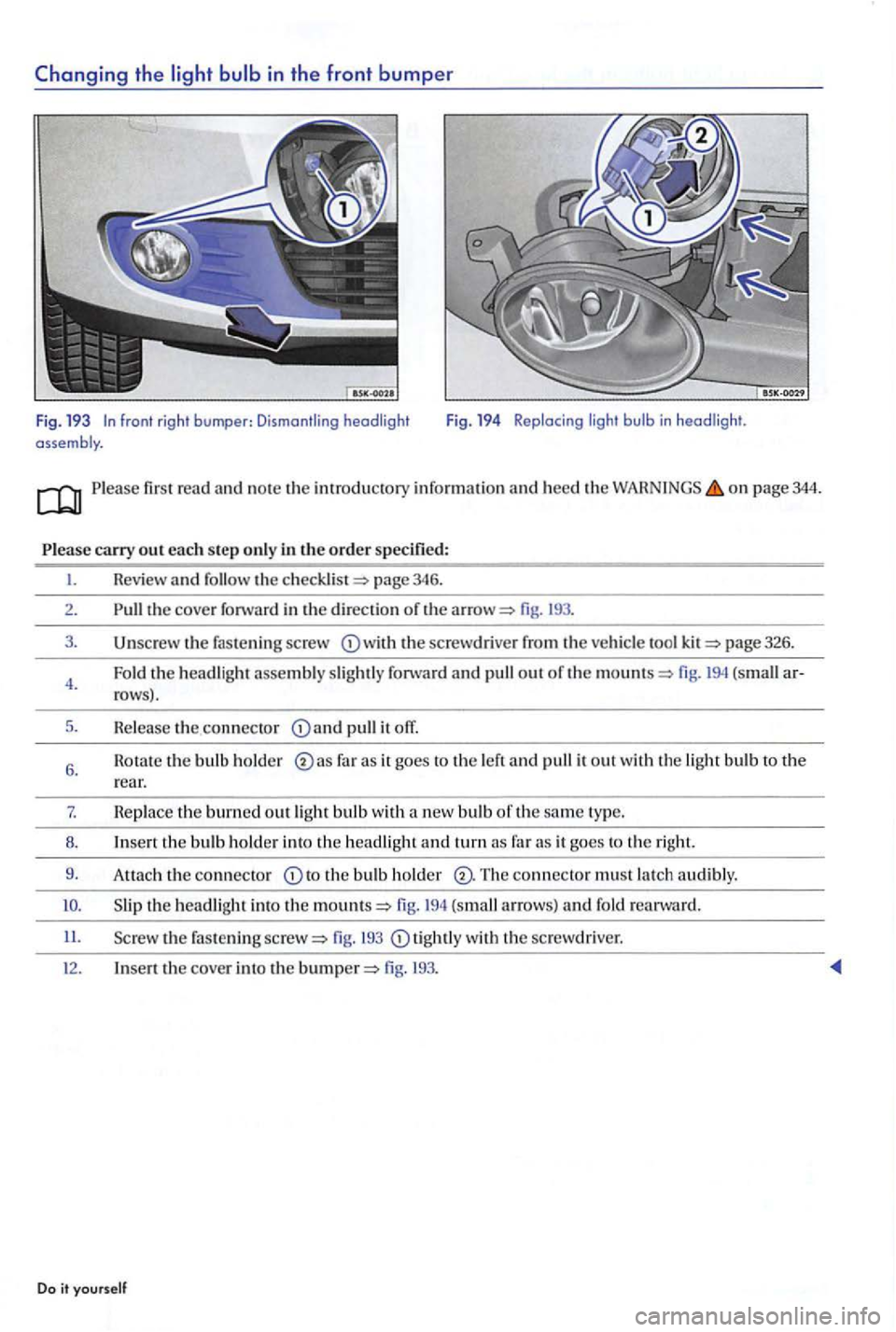
firs t read and n o te th e information and heed the o n page 344.
the cove r forward in the direction or the fig.
fas te n in g sc rew the screwdrive r the ve hicle page 32 6.
Fold the headlig
ht assembly slig htl y and pull out or the fig. (small row s).
H e le a
se th e connector pull it ofT.
H o tat e the bulb ho ld e r as it goes to the a nd pull it out with the ligh t bulb to the rear.
7. H e place the burned out light bulb w ith a new bulb of the sam e type.
8 .
to the bul b holder Th e connector must latch audibly.
10. fig . (s m all arrows) a nd fo ld
the fastening fig. tig h tly wit h the sc rewdrive r.
t h e cover into the fig .
Do it yourself
Page 347 of 541
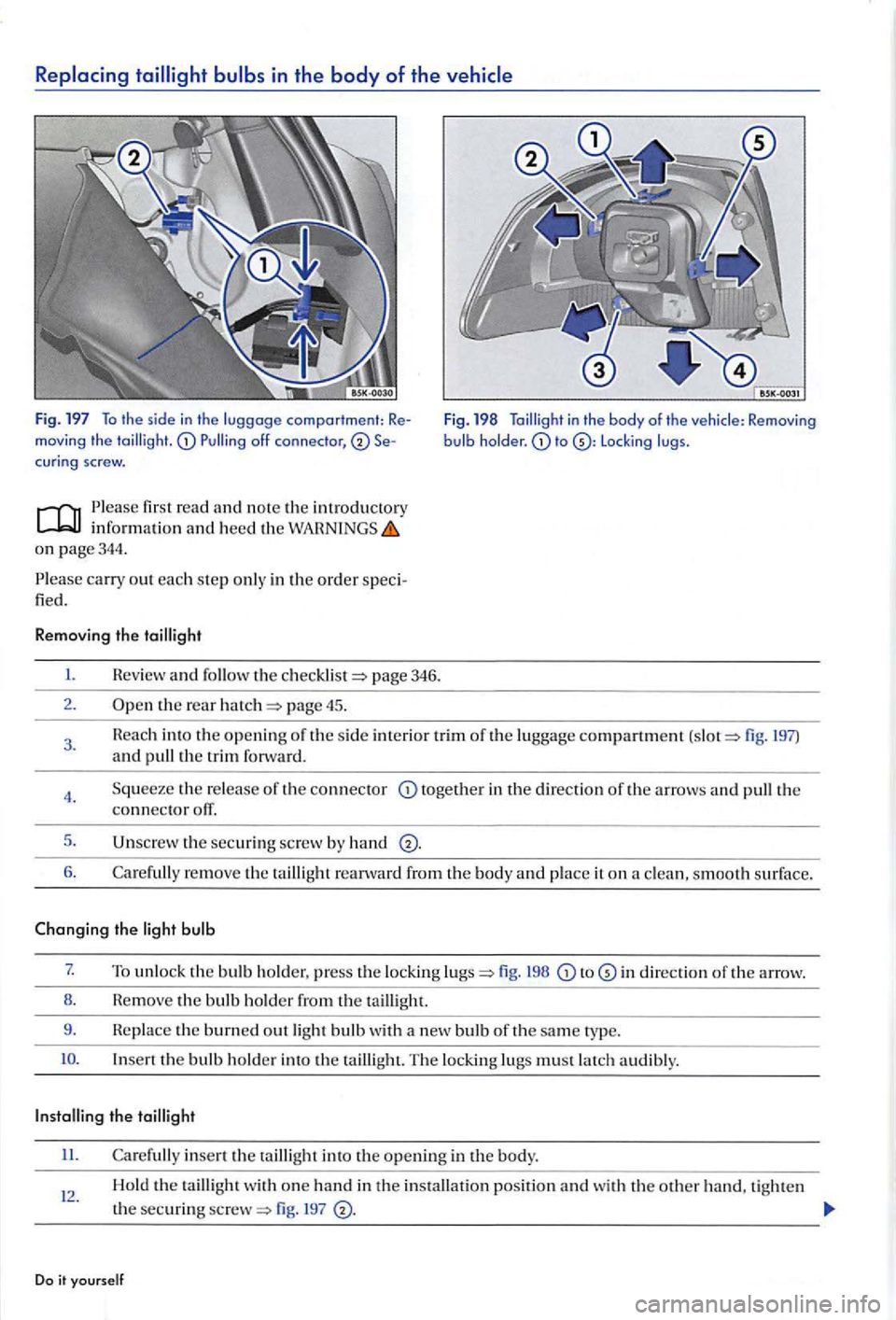
Replacing tailligh t bulbs in the body of the vehicle
fig. 197 To th e s id e in th e luggage comportment: Remov ing th e cur in g screw.
Please fir st read
o n page 344 .
P l
ease carry out each ste p onl y in the order speci
fied.
Removing the
I. Review and the page 346.
2 . the rear page 45.
Fig. 198 to L oc king lugs .
3. 197) and pull the trim forwa rd .
4.
5.
6.
the re lease of th e connector together in th e direction of the arrows and th e connector otT.
th e securing screw by hand
Care full y re move th e taillig ht reanvard from th e body and place it on a clea n , s mooth surface.
Changing the light bulb
7. To unlock the bulb hold er, press th e locking fig. 198 to in direction th e arrow.
8 . Hem
ove th e bulb ho lder th e ta illi ght.
9 . Re
place the burned out light bulb w ith a n ew bulb or the same t ype.
Insert the bulb holde r into the tailli gh t. The lockin g lugs must latch a udibly.
II. Carefull y insert th e ta illight into the op en in g in the body.
12 . Hold the ta illight w ith o ne hand in th e in stallatio n position and wi th the othe r hand, tighte n
t h e
securing 197
Do it yo urself
Page 484 of 541
N
N
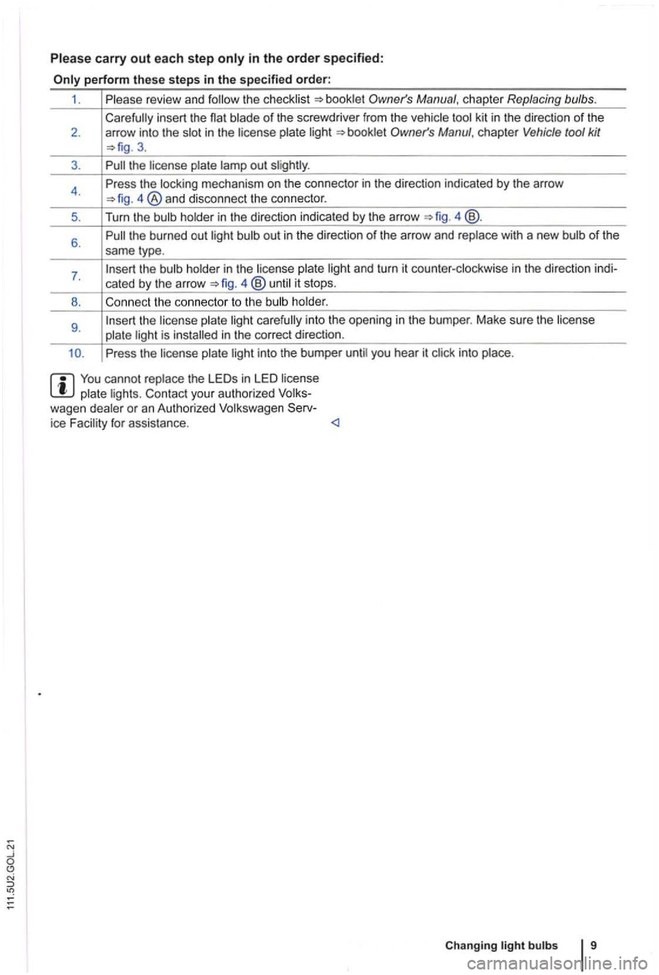
Please carry out each step only in the order specified:
the c hecklist
blade of the screwdr iver from the vehicle
3.
3 .
the license plate out
4. Pre
ss the locking mechanism on the connector in the direction indicated by the arr ow
4 @ .
6. the burned out light out in the direction of the arrow and replace with a new of the
same type.
7.
holder.
9 . the license plate light
Press the license plate light into the bumper until you hear it click into place .
You cannot replace the in LED license plate lights. your authorized wagen dealer or an Authorized Volkswagen ice Facility for assistance .