Page 394 of 436

’07 HIGHLANDER HV_U (L/O 0608)
382
2007 HIGHLANDER HV from July ’06 Prod. (OM48685U)
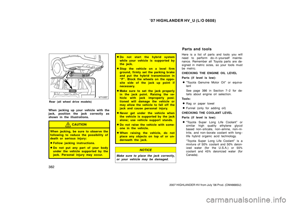
Rear (all wheel drive models)
When jacking up your vehicle with the
jack, position the jack correctly as
shown in the illustrations.
CAUTION
When jacking, be sure to observe the
following to reduce the possibility of
death or serious injury:
�Follow jacking instructions.
�Do not put any part of your body
under the vehicle supported by the
jack. Personal injury may occur.
�Do not start the hybrid system
while your vehicle is supported by
the jack.
�Stop the vehicle on a level firm
ground, firmly set the parking brake
and put the hybrid transmission in
“P”. Block the wheels on the oppo-
site side of the jack up point if
necessary.
�Make sure to set the jack properly
in the jack point. Raising the ve-
hicle with jack improperly posi-
tioned will damage the vehicle or
may allow the vehicle to fall off the
jack and cause personal injury.
�Never get under the vehicle when
the vehicle is supported by the jack
alone; use vehicle support stands.
�Do not raise the vehicle with some-
one in the vehicle.
�When raising the vehicle, do not
place any objects on top of or un-
derneath the jack.
NOTICE
Make sure to place the jack correctly,
or your vehicle may be damaged.
Here is a list of parts and tools you will
need to perform do−it−yourself mainte-
nance. Remember all Toyota parts are de-
signed in metric sizes, so your tools must
be metric.
CHECKING THE ENGINE OIL LEVEL
Parts (if level is low):
�“Toyota Genuine Motor Oil” or equiva-
lent
See page 386 in Section 7− 2 for de-
tails about engine oil selection.
Tools:
�Rag or paper towel
�Funnel (only for adding oil)
CHECKING THE COOLANT LEVEL
Parts (if level is low):
�“Toyota Super Long Life Coolant” or
similar high quality ethylene glycol
based non −silicate, non −amine, non− ni-
trite, and non −borate coolant with long −
life hybrid organic acid technology.
“Toyota Super Long Life Coolant” is a
mixture of 50% coolant and 50% deion-
ized water (for the U.S.A.) or 55%
coolant and 45% deionized water (for
Canada).
Parts and tools
Page 409 of 436

’07 HIGHLANDER HV_U (L/O 0608)
397
2007 HIGHLANDER HV from July ’06 Prod. (OM48685U)
NOTICE
If the wrong combination of tire and
chain is used, the chains could dam-
age the vehicle body.
CHAIN INSTALLATION
Install the chains on the front tires as
tightly as possible. Do not use tire
chains on the rear tires. Retighten
chains after driving 0.5—1.0 km
(1/4—1/2 mile).
When installing chains on your tires, care-
fully follow the instructions of the chain
manufacturer.
If wheel covers are used, they will be
scratched by the chain band, so remove
the covers before putting on the chains.
CAUTION
�Do not exceed 50 km/h (30 mph) or
the chain manufacturer ’s recom-
mended speed limit, whichever is
lower.
�Drive carefully avoiding bumps,
holes, and sharp turns, which may
cause the vehicle to bounce.
�Avoid sharp turns or locked�wheel
braking, as use of chains may ad-
versely affect vehicle handling.
�When driving with chains installed,
be sure to drive carefully. Slow
down before entering curves to
avoid losing control of the vehicle.
Otherwise an accident may occur.
WHEN TO REPLACE YOUR WHEELS
If you have wheel damage such as
bending, cracks or heavy corrosion, the
wheel should be replaced.
If you fail to replace a damaged wheel,
the tire may slip off the wheel or cause
loss of handling control.
WHEEL SELECTION
When replacing wheels, care should be
taken to ensure that the wheels are re-
placed by ones with the same load ca-
pacity, diameter, rim width, and offset.
Correct replacement wheels are available
at your Toyota dealer.
A wheel of a different size or type may
adversely affect handling, wheel and bear-
ing life, brake cooling, speedometer/odom-
eter calibration, stopping ability, headlight
aim, bumper height, vehicle ground clear-
ance, and tire or snow chain clearance to
the body and chassis.
Replacing wheels
Page 417 of 436
’07 HIGHLANDER HV_U (L/O 0608)
405
2007 HIGHLANDER HV from July ’06 Prod. (OM48685U)
A: HB4 halogen bulbs
B: HB3 halogen bulbs
C: Single end bulbs
D: Wedge base bulbs (amber)
E: Wedge base bulbs (clear)
F: Double end bulbs
1. Open the hood. Turn the bulb basecounterclockwise to the front of the
vehicle as shown.2. Pull the bulb out of the bulb baseand install a new bulb.
If the connector is tight, wiggle it.
—Headlights
Page 418 of 436
’07 HIGHLANDER HV_U (L/O 0608)
406
2007 HIGHLANDER HV from July ’06 Prod. (OM48685U)
3. Insert the bulb base into the mount-ing hole by turning it clockwise.
Aiming is not necessary after replacing
the bulb. When aiming adjustment is nec-
essary, contact your Toyota dealer. If any of the following lights burns out,
contact your Toyota dealer.
�Front fog lights
�Front turn signals/parking and front
side marker lights
�Rear side marker lights
NOTICE
Do not try to replace any of the light
bulbs mentioned above by yourself.
You may damage the vehicle.
—Front fog, front turn signal/
parking and front side marker,
and rear side marker lights
—Rear turn signal and
back�up lights
Page 429 of 436

’07 HIGHLANDER HV_U (L/O 0608)
417
2007 HIGHLANDER HV from July ’06 Prod. (OM48685U)
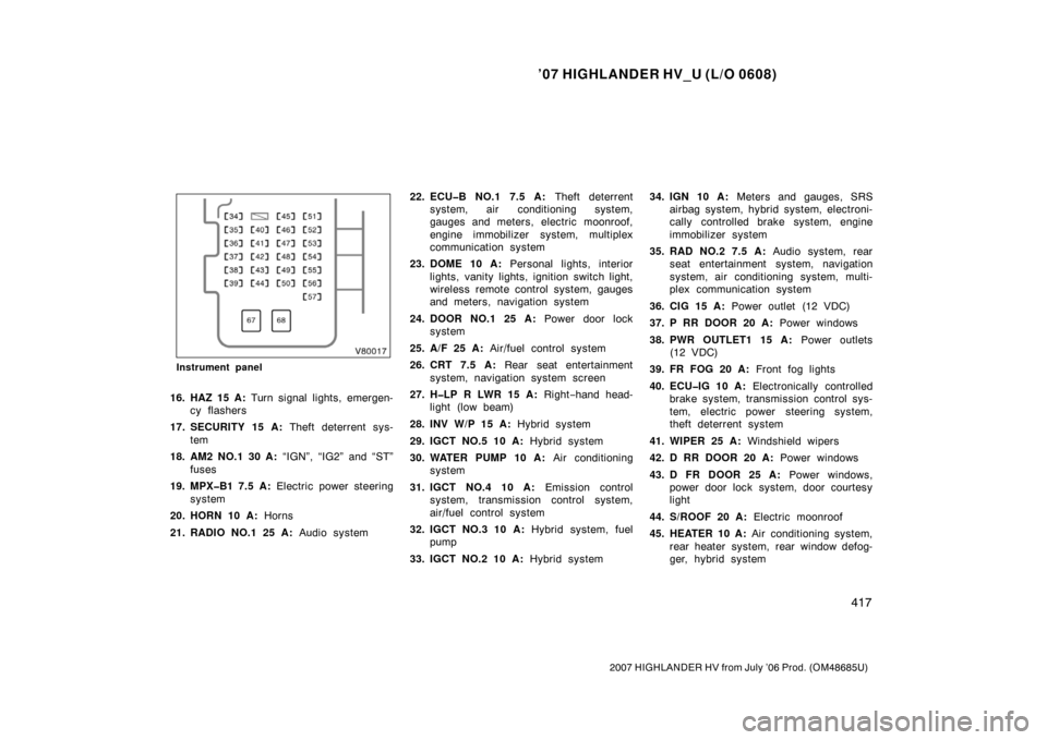
Instrument panel
16. HAZ 15 A: Turn signal lights, emergen-
cy flashers
17. SECURITY 15 A: Theft deterrent sys-
tem
18. AM2 NO.1 30 A: “IGN”, “IG2” and “ST”
fuses
19. MPX�B1 7.5 A: Electric power steering
system
20. HORN 10 A: Horns
21. RADIO NO.1 25 A: Audio system22. ECU�B NO.1 7.5 A:
Theft deterrent
system, air conditioning system,
gauges and meters, electric moonroof,
engine immobilizer system, multiplex
communication system
23. DOME 10 A: Personal lights, interior
lights, vanity lights, ignition switch light,
wireless remote control system, gauges
and meters, navigation system
24. DOOR NO.1 25 A: Power door lock
system
25. A/F 25 A: Air/fuel control system
26. CRT 7.5 A: Rear seat entertainment
system, navigation system screen
27. H�LP R LWR 15 A: Right−hand head-
light (low beam)
28. INV W/P 15 A: Hybrid system
29. IGCT NO.5 10 A: Hybrid system
30. WATER PUMP 10 A: Air conditioning
system
31. IGCT NO.4 10 A: Emission control
system, transmission control system,
air/fuel control system
32. IGCT NO.3 10 A: Hybrid system, fuel
pump
33. IGCT NO.2 10 A: Hybrid system34. IGN 10 A:
Meters and gauges, SRS
airbag system, hybrid system, electroni-
cally controlled brake system, engine
immobilizer system
35. RAD NO.2 7.5 A: Audio system, rear
seat entertainment system, navigation
system, air c onditioning system, multi-
plex communication system
36. CIG 15 A: Power outlet (12 VDC)
37. P RR DOOR 20 A: Power windows
38. PWR OUTLET1 15 A: Power outlets
(12 VDC)
39. FR FOG 20 A: Front fog lights
40. ECU�IG 10 A: Electronically controlled
brake system, transmission control sys-
tem, electric power steering system,
theft deterrent system
41. WIPER 25 A: Windshield wipers
42. D RR DOOR 20 A: Power windows
43. D FR DOOR 25 A: Power windows,
power door lock system, door courtesy
light
44. S/ROOF 20 A: Electric moonroof
45. HEATER 10 A: Air conditioning system,
rear heater system, rear window defog-
ger, hybrid system
Page 430 of 436

’07 HIGHLANDER HV_U (L/O 0608)
418
2007 HIGHLANDER HV from July ’06 Prod. (OM48685U)
46. IG1 7.5 A: Hybrid system, power door
lock system, multiplex communication
system, airbag on −off indicator lights,
turn signal lights, back −up lights, out-
side rear view mirror defoggers, auto
anti −glare inside rear view mirror, pow-
er outlet (115 VAC), seat heaters, navi-
gation system
47. RR WIP 15 A: Rear window wiper
48. STOP 20 A: Stop lights, high mounted
stoplight, electronically controlled brake
system, transmission control system,
hybrid system
49. OBD 7.5 A: On−board diagnosis sys-
tem
50. SEAT HTR 15 A: Seat heaters
51. IG2 15 A: Multiport fuel injection sys-
tem/sequential fuel injection system,
engine ignition system
52. WASHER 20 A: Windshield washer,
rear window washer
53. FUEL OPN 7.5 A: Fuel filler door
opening system
54. FR DEF 20 A: Windshield wiper deicer,
rear view mirror defoggers
55. P FR DOOR 20 A: Power windows,
door courtesy light 56. TAIL 10 A:
Parking lights, tail lights,
side marker lights, license plate lights,
front fog lights
57. PANEL 7.5 A: Instrument panel lights
Fuses (type B)
58. ABS MTR2 30 A: Electronically con-
trolled brake system
59. ABS MTR1 30 A: Electronically con-
trolled brake system
60. HEATER 50 A: Air conditioning system,
“WATER PUMP” fuse
61. RR HTR 30 A: Rear heater system
62. RR DEF 30 A: Rear window defogger
63. RDI FAN NO.1 40 A: Electric cooling
fan
64. RDI FAN NO.2 40 A: Electric cooling
fan
65. MAIN 40 A: “H−LP L LWR”, “H −LP L
UPR”, “H− LP R LWR”, “H −LP R UPR”
and “DRL” fuses
66. IGCT NO.1 50 A: “INV W/P”, “IGCT
NO.2”, “IGCT NO.3”, “IGCT NO.4” and
“IGCT NO.5” fuses
67. AM1 40 A: “ECU−IG”, “WASHER”,
“IG1”, “WIPER”, “RR WIP”, “HEATER
(10 A)”, “RAD NO.2” and “CIG” fuses
68. POWER 30 A: Power seat Fuses (type C)
69. DC/DC 120 A: Hybrid system