Page 168 of 404

160
If the brake pedal is depressed, the in-
dicator light will turn green, regardless
of which mode is selected. When the
indicator light is green, pressing the
“ENGINE START STOP” switch once
starts the engine. (For starting tips, see
“How to start the engine” on page 296
in Section 3.)
If the amber indicator light on the
“ENGINE START STOP” switch blinks, this
indicates a malfunction of the push start
system. Turn off the engine immediately
and contact your Toyota dealer.
Approximately five hours after the engine
is turned off, you may hear sound coming
from underneath the luggage compartment
for several minutes. This is normal opera-
tion and does not indicate a malfunction.
(See “Leak detection pump” on page viii.)
It is not a malfunction if the needle on all
meters and gauges move slightly when the
ignition switch is set at ACC, ON or when
the engine starts.
NOTICE
Do not leave the ignition switch at
ON if the engine is not running. The
battery will discharge and the ignition
could be damaged.
When the battery is disconnected or
run down, the push button start function
memorizes the current mode. After you
reconnect, replace, or recharge the bat-
tery, the memorized mode is selected au-
tomatically. In any of these cases, turn off
the engine if the engine comes on.
Page 256 of 404

248
The compass indicates the direction
that the vehicle is heading. In the
above case, it shows that the vehicle is
heading north.Displays
Directions
N
NE E
SE
S
SW W
NWNorth
Northeast East
Southeast
South
Southwest West
Northwest
The compass may not show the correct
direction in the following conditions:
�The vehicle is stopped immediately af-
ter turning.
�The compass does not adjust while the
vehicle is stopped.
�The ignition switch is turned off imme-
diately after turning.
�The vehicle is on an inclined surface.
�The vehicle is in a place where the
earth’s magnetic field is subject to in-
terference by artificial magnetic fields
(underground parking, under a steel
tower, between buildings, roof parking,
near a crossing, near a large vehicle,
etc.).
�The vehicle is magnetized. (There is a
magnet or a metal object on or near
the inside rear view mirror.)
�The battery has been disconnected.
If your vehicle is out of the set zone,
refer to “CALIBRATING THE COMPASS”
below to set the zone number.
If the deviation is small, the compass
works to calibrate the direction automati-
cally while the vehicle is in motion.
For additional precision or for complete
calibrating, see “CALIBRATING THE
COMPASS” below.
The compass sensor is in the inside
rear view mirror.
NOTICE
Do not put magnets or a metal object
on or near the inside rear view mirror
of the vehicle. Doing this may cause
malfunction of the compass sensor.
Page 259 of 404

Sometimes the direction display on the
compass may not change after a turn. To
rectify this, stop the vehicle and push and
hold the “
” switch")
251
CALIBRATING THE COMPASS (circling
calibration)
Sometimes the direction display on the
compass may not change after a turn. To
rectify this, stop the vehicle and push and
hold the “
” switch until “C” appears on
the display.
If “C” appears on the display because of
a drastic change in the magnetic field,
perform circling calibration.
Drive the vehicle in a circle at 8 km/h (5
mph) or less. If there is not enough space
to drive in a circle, drive around the
block.
After driving 1 to 3 circles in the above
method, calibration is completed when the
direction is shown on the display.
If calibration cannot be performed because
of the magnetized vehicle etc., take your
vehicle to Toyota dealer. Perform circling calibration just after
you have purchased your Toyota. And
then always perform circling calibration
after the battery has been removed, re-
placed or disconnected.
�Do not perform circling calibration of
the compass in a place where the
earth’s magnetic field is subject to in-
terference by artificial magnetic fields
(underground parking, under a steel
tower, between buildings, roof parking,
near a crossing, near a large vehicle,
etc.).
�During calibration, do not operate elec-
tric systems (moon roof, power win-
dows, etc.) as they may interfere with
the calibration.
Page 261 of 404
253
CAUTION
To reduce the chance of injury in
case of an accident or sudden stop
while driving, always completely close
the ashtray after use.
Rear console box
Center auxiliary box
The power outlets are designed for
power supply for car accessories.
The ignition switch must be set at ACC
or ON for the power outlet to be used.
NOTICE
�To prevent the fuse from being
blown, do not use the electricity
over the total vehicle capacity of 12
V/120W.
� To prevent the battery from being
discharged, do not use the power
outlet longer than necessary when
the engine is not running.
� Close the power outlet lids when
the power outlets are not in use.
Inserting anything other than an ap-
propriate plug that fits the outlet,
or allowing any liquid to get into
the outlet may cause electrical fail-
ure or short circuits.
Power outlets
Page 262 of 404
 is manufactured
under license from HomeLink� and can
be programmed to operate garage
doors, gates, entry doors, door locks,")
254
Indicator lightButtons
The garage door opener (�
Universal Transceiver) is manufactured
under license from HomeLink� and can
be programmed to operate garage
doors, gates, entry doors, door locks,
home lighting systems, and security
systems, etc. (a) Programming the HomeLink
�
The HomeLink� in your vehicle has 3
buttons and you can store one program
for each button.
To ensure correct programming into the
HomeLink
�, install a new battery in the
hand− held transmitter prior to program-
ming.
The battery side of the hand −held trans-
mitter must be pointed away from the
HomeLink
� during the programming pro-
cess.
For Canadian users, follow the procedure
in “Programming an entrance gate/Pro-
gramming all devices in the Canadian
market”.
1. Decide which of 3 HomeLink
� buttons
you want to program.
HomeLink �
Hand −held
garage
transmitter 25 to
75 mm
(1 to 3 in.)
2. Place your hand
−held garage transmit-
ter 25 to 75 mm (1 to 3 in.) away from
the surface of the HomeLink
�.
Keep the indicator light on the HomeLink
�
in view while programming.
Garage door opener
Page 270 of 404
262
NOTICE
�To prevent the vehicle battery from
being discharged, always operate
the sunshade while the engine is
running.
� Observe the following to avoid dam-
age and/or malfunction:
Do not overload the sunshade mo-
tor and other parts (for instance by
pushing down on the sunshade
bracket while it is opening).
Do not place anything where they
may hinder the opening/closing of
the sunshade.
Do not affix anything to the sun-
shade.
Clean the sunshade groove if there
is any foreign matter or dust on it.
Do not operate the rear electric
sunshade repeatedly for a long time
as its motor may overheat.
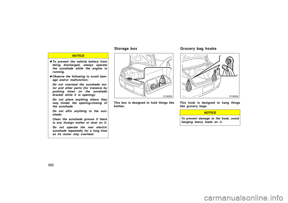
This box is designed to hold things like
bottles.This hook is designed to hang things
like grocery bags.
NOTICE
To prevent damage to the hook, avoid
hanging heavy loads on it.
Storage box Grocery bag hooks
Page 295 of 404
 times the number of occupants specified in the second
column of Table 1 that follows
Occupant distributiondistribution of occupa")
287
Ti r e relat ed ter m
Meaning
Normal occupant weight68 kg (150 lb.) times the number of occupants specified in the second
column of Table 1 that follows
Occupant distributiondistribution of occupants in a vehicle as specified in the third column of Table
1 that follows
Production options weight
the combined weight of those installed regular production options weighing
over 2.3 kg (5 lb.) in excess of those standard items which they replace,
not previously considered in curb weight or accessory weight, including
heavy duty brakes, ride levelers, roof rack, heavy duty battery, and special
trim
Recommended inflation pressurecold tire inflation pressure recommended by a manufacturer
Rima metal support for a tire or a tire and tube assembly upon which the tire beads
are seated
Rim diameter (Wheel diameter)nominal diameter of the bead seat
Rim size designationrim diameter and width
Rim type designationthe industry of manufacturer ’s designation for a rim by style or code
Rim widt hnominal distance between rim flanges
Vehicle capacity weight
(Total load capacity)the rated cargo and luggage load plus 68 kg (150 lb.) times the vehicle’s desig-
nated seating capacity
Vehicle maximum load on the tirethe load on an individual tire that is determined by distributing to each axle
its share of the maximum loaded vehicle weight and dividing by two
Page 306 of 404
, it is possible to start the engine.
With the brake pedal firmly depressed, the
indicator light on the “ENGINE START
STOP” switch will turn gr")
298
When the key is in the vehicle (on your
person), it is possible to start the engine.
With the brake pedal firmly depressed, the
indicator light on the “ENGINE START
STOP” switch will turn green. Check that
the automatic transmission selector lever
is in the “P” position. Pressing the “EN-
GINE START STOP” switch once starts
the engine.
Press the “ENGINE START STOP” switch
slowly and firmly.
Engine should be warmed up by driving,
not in idle. For warming up, drive with
smoothly turning engine until engine cool-
ant temperature is within normal range.
If the engine stalls...
Simply restart it, using the correct proce-
dure given in normal starting.
If the engine will not start...
In the following cases, the engine will not
start.
�If a buzzer sounds from the vehicle
and the smart key system warning light
comes on when pressing the “ENGINE
START STOP” switch, this indicates
that the key is not in the vehicle.
�If the key is placed in the trunk.
�There are instances in which the en-
gine will not start, even if the key is
in the vehicle (e.g. on the floor, in the
cup holder or glove box).When the push button start function
does not operate properly, the following
may be causes:
�The key battery may be discharged if
the electronic key does not work.
You can start the engine by touching
the Toyota logo side of the electronic
key to the “ENGINE START STOP”
switch. For derails, see “Smart key
system” on page 27 in Section 1
−2.
Replace the key battery as soon as
possible. (See “—Replacing battery” on
page 25 in Section 1 −2.)
�The engine was repeatedly turned on
and off over a short period.
Wait 10 seconds and then start the
engine.