2007 SUZUKI SWIFT Vent
[x] Cancel search: VentPage 842 of 1496

Downloaded from www.Manualslib.com manuals search engine 5B-28 Manual Transmission/Transaxle:
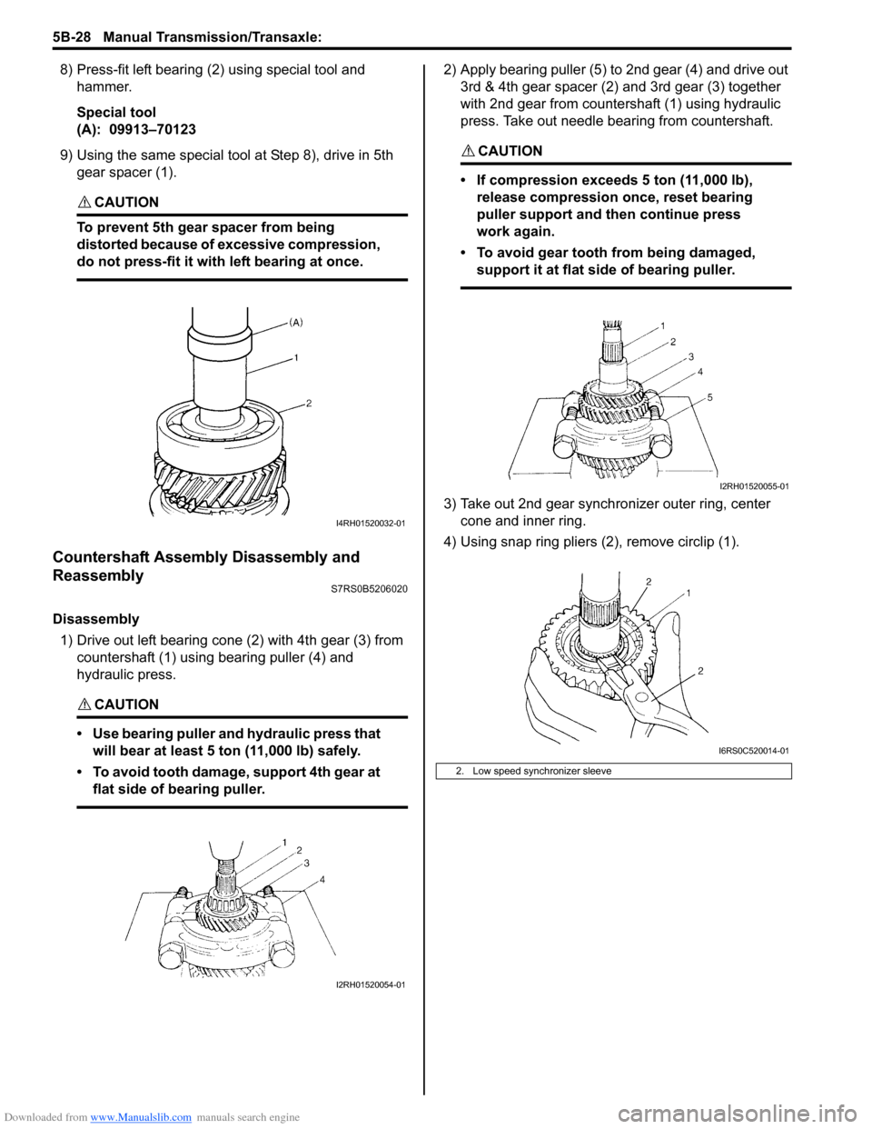
8) Press-fit left bearing (2) using special tool and hammer.
Special tool
(A): 09913–70123
9) Using the same special tool at Step 8), drive in 5th
gear spacer (1).
CAUTION!
To prevent 5th gear spacer from being
distorted because of excessive compression,
do not press-fit it with left bearing at once.
Countershaft Assembly Disassembly and
Reassembly
S7RS0B5206020
Disassembly
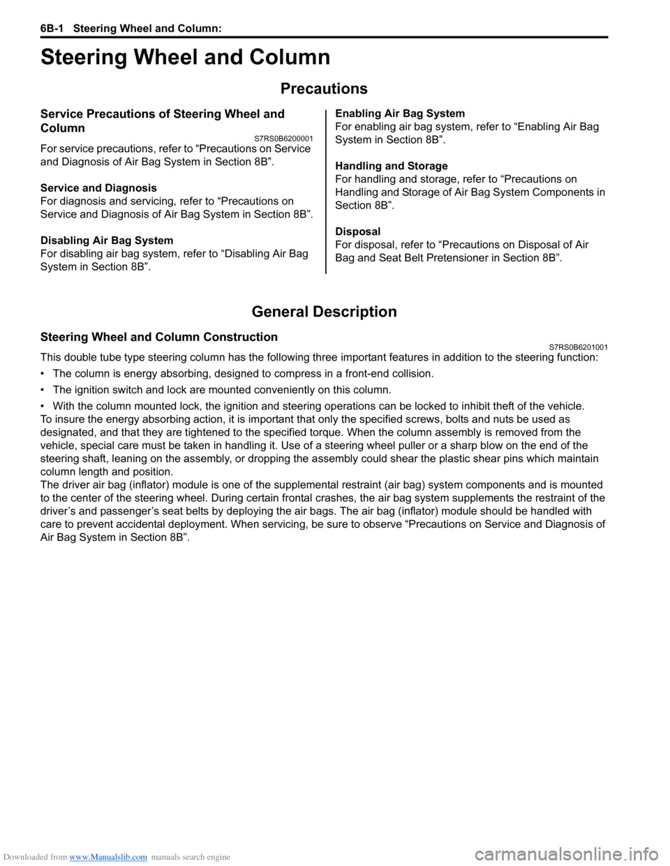
1) Drive out left bearing cone (2) with 4th gear (3) from countershaft (1) using bearing puller (4) and
hydraulic press.
CAUTION!
• Use bearing puller and hydraulic press that will bear at least 5 ton (11,000 lb) safely.
• To avoid tooth damage, support 4th gear at flat side of bearing puller.
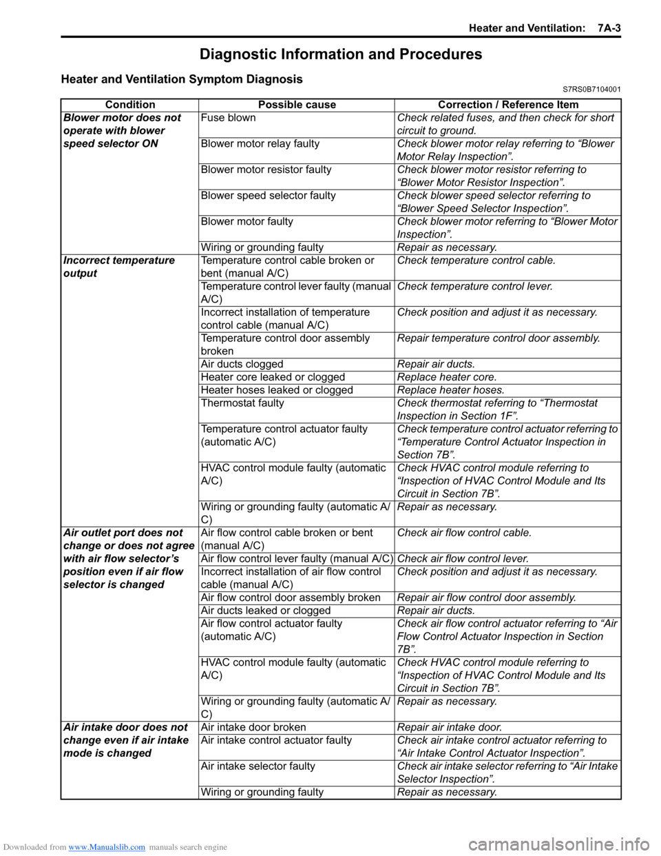
2) Apply bearing puller (5) to 2nd gear (4) and drive out 3rd & 4th gear spacer (2) and 3rd gear (3) together
with 2nd gear from countershaft (1) using hydraulic
press. Take out needle bearing from countershaft.
CAUTION!
• If compression exceeds 5 ton (11,000 lb), release compression once, reset bearing
puller support and then continue press
work again.
• To avoid gear tooth from being damaged, support it at flat side of bearing puller.
3) Take out 2nd gear synchronizer outer ring, center cone and inner ring.
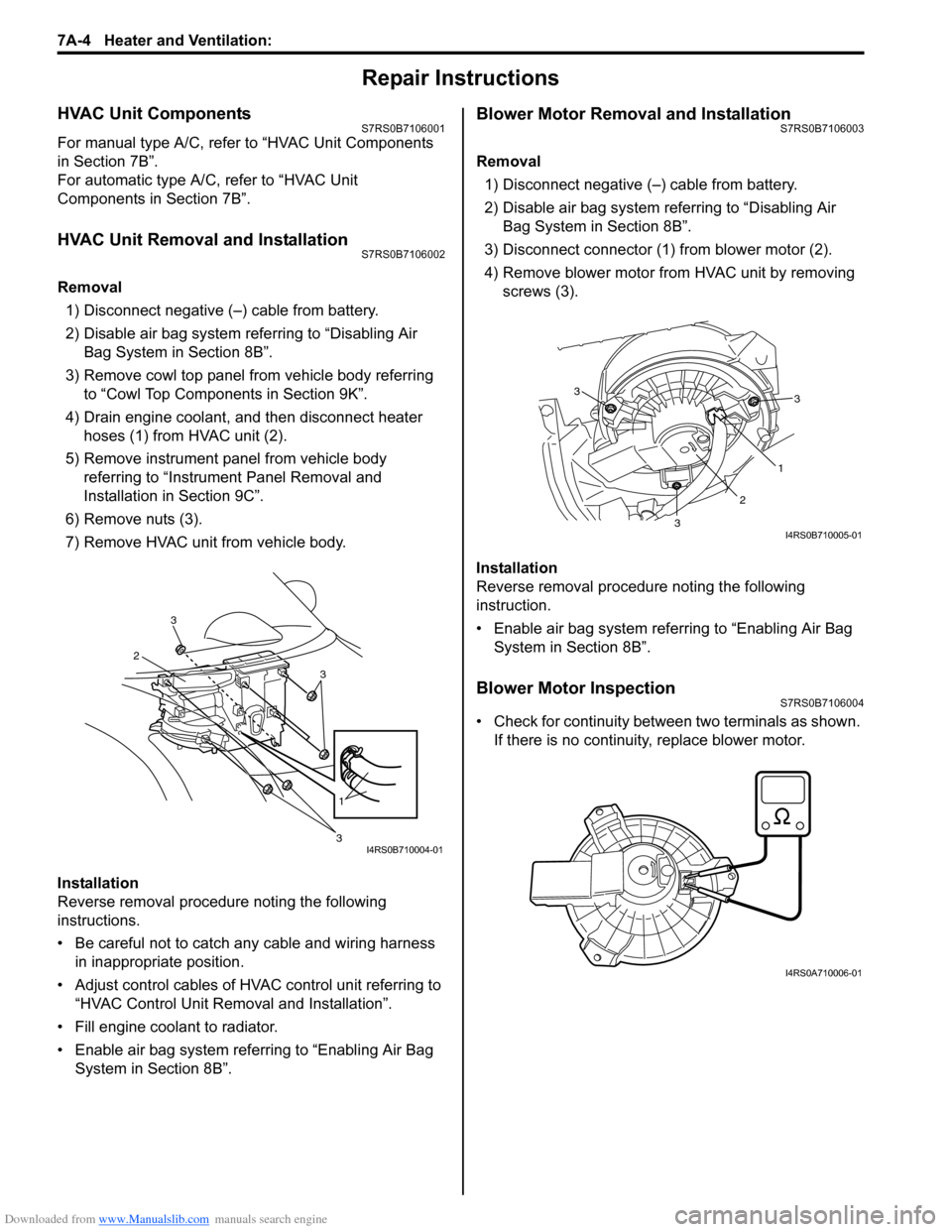
4) Using snap ring pliers (2), remove circlip (1).
I4RH01520032-01
I2RH01520054-01
2. Low speed synchronizer sleeve
I2RH01520055-01
I6RS0C520014-01
Page 872 of 1496

Downloaded from www.Manualslib.com manuals search engine 6B-1 Steering Wheel and Column:
Steeri ng
Steering Wheel and Column
Precautions
Service Precautions of Steering Wheel and
Column
S7RS0B6200001
For service precautions, refer to “Precautions on Service
and Diagnosis of Air Bag System in Section 8B”.
Service and Diagnosis
For diagnosis and servicing, refer to “Precautions on
Service and Diagnosis of Air Bag System in Section 8B”.
Disabling Air Bag System
For disabling air bag system, refer to “Disabling Air Bag
System in Section 8B”. Enabling Air Bag System
For enabling air bag system, refer to “Enabling Air Bag
System in Section 8B”.
Handling and Storage
For handling and storage, refer to “Precautions on
Handling and Storage of Air Bag System Components in
Section 8B”.
Disposal
For disposal, refer to “Prec
autions on Disposal of Air
Bag and Seat Belt Pretensioner in Section 8B”.
General Description
Steering Wheel and Column ConstructionS7RS0B6201001
This double tube type steering column has the following three important features in addition to the steering function:
• The column is energy absorbing, desig ned to compress in a front-end collision.
• The ignition switch and lock are mounted conveniently on this column.
• With the column mounted lock, the ignition and steering op erations can be locked to inhibit theft of the vehicle.
To insure the energy absorbing action, it is important th at only the specified screws, bolts and nuts be used as
designated, and that they are tightened to the specified torque. When the column assembly is removed from the
vehicle, special care must be taken in handling it. Use of a steering wheel puller or a sharp blow on the end of the
steering shaft, leaning on the assembly, or dropping the a ssembly could shear the plastic shear pins which maintain
column length and position.
The driver air bag (inflator) module is one of the supplemental restraint (air bag) system components and is mounted
to the center of the steering wheel. During certain frontal crashes, the air bag system supplements the restraint of the
driver’s and passenger’s seat belts by deploying the air b ags. The air bag (inflator) module should be handled with
care to prevent accidental deployment. When servicing, be sure to observe “Precautions on Service and Diagnosis of
Air Bag System in Section 8B”.
Page 887 of 1496

Downloaded from www.Manualslib.com manuals search engine Power Assisted Steering System: 6C-5
Terminal Arrangement of P/S Control Module Coupler (Viewed from Harness Side)
Diagnostic Information and Procedures
EPS System CheckS7RS0B6304001
WARNING!
Carry out test drive in light traffic area to prevent an accident.
Refer to the following items for the details of each step.Terminal Circuit Terminal Circuit
E49-1 Main power supply for internal memory
and EPS motor E52-9 Ground for torque sensors
E49-2 Ground for P/S control module E52-10 —
E51-1 Motor output 1 E52-11 Serial communication for data link
connector
E51-2 Motor output 2 E52-12 Engine speed signal
E52-1 Ignition switch signal for P/S control
module E52-13 —
E52-2 — E52-14 P/S operation signal (idle up signal)
E52-3 — E52-15 —
E52-4 Vehicle speed signal E52-16 Torque sensor internal failure signal
E52-5 “EPS” warning light E52-17 —
E52-6 Torque sensor signal (Sub) E52-18 Torque sensor signal (Main)
E52-7 — E52-19 Ground for shield wire
E52-8 Main power supply for torque sensor E52-20 5 V reference power supply for torque
sensor
Step
Action YesNo
1 �) Customer complaint analysis
1) Perform customer complaint analysis referring to “Customer Complaint Analysis”.
Was customer complaint analysis performed? Go to Step 2.
Perform customer
complaint analysis.
2 �) DTC check, record and clearance
1) Check for DTC (including pending DTC) referring to “DTC Check”, Record and Clearance.
Is there any DTC(s)? Print DTC or write them
down and clear them by
referring to “DTC
Clearance” and go to
St ep 3 .Go to Step 4.
3 �) Visual inspection
1) Perform visual inspection referring to “Visual Inspection”.
Is there any faulty condition? Repair or replace
malfunction part, and go
to Step 11.
Go to Step 5.
4 �) Visual inspection
1) Perform visual inspection referring to “Visual Inspection”.
Is there any faulty condition? Repair or replace
malfunction part, and go
to Step 11.
Go to Step 8.
5 �) Trouble symptom confirmation
1) Confirm trouble symptom referring to “Trouble Symptom Confirmation”.
Is trouble symptom identified? Go to Step 6.
Go to Step 7.
6 �) Rechecking and record of DTC
1) Recheck for DTC referring to “DTC Check”.
Is there any DTC(s)? Go to Step 9.
Go to Step 8.
Page 933 of 1496

Downloaded from www.Manualslib.com manuals search engine Table of Contents 7- i
7
Section 7
CONTENTS
HVAC
Precautions ................................................. 7-1
Precautions............................................................. 7-1
Precautions on HVAC ........................................... 7-1
Heater and Ventilation.... ......................... 7A-1
General Description ............................................. 7A-1
Heater and Ventilation Construction ................... 7A-1
Schematic and Routing Diagram ........................ 7A-2 Heater and Ventilation Wiring Circuit Diagram .... 7A-2
Diagnostic Information and Procedures ............ 7A-3 Heater and Ventilation Symptom Diagnosis........ 7A-3
Repair Instructions .............................................. 7A-4 HVAC Unit Components ..................................... 7A-4
HVAC Unit Removal and Installation .................. 7A-4
Blower Motor Removal and Installation............... 7A-4
Blower Motor Inspection ..................................... 7A-4
Blower Motor Resistor Removal and Installation ......................................................... 7A-5
Blower Motor Resistor Inspection ....................... 7A-5
Blower Motor Relay Inspection ........................... 7A-6
HVAC Control Unit Components ......................... 7A-6
HVAC Control Unit Remova l and Installation ...... 7A-7
Blower Speed Selector In spection ...................... 7A-9
Air Intake Selector Inspec tion ............................. 7A-9
Air Intake Control Actuator Removal and Installation ......................................................... 7A-9
Air Intake Control Actuator Inspection .............. 7A-10
Center Ventilation Louver Removal and Installation ....................................................... 7A-10
Side Ventilation Louver Removal and Installation ....................................................... 7A-11
HVAC Air Filter Removal and Installation (If Equipped)........................................................ 7A-12
HVAC Air Filter Inspection (If Equipped) ........... 7A-12
Air Conditioning System... ...................... 7B-1
Manual Type ............................................................ 7B-1
Precautions........................................................... 7B-1A/C System Caution ............................................ 7B-1
Precautions on Servicing A/C System ................ 7B-1
General Description ............................................. 7B-3 Refrigerant Type Identifica tion ............................ 7B-3
Sub-Cool A/C System Description ...................... 7B-4
A/C Operation Description .................................. 7B-4 Schematic and Routing Diagram ........................7B-5
Major Components of A/C System ...................... 7B-5
A/C System Wiring Diagram ............................... 7B-6
Diagnostic Information and Procedures ............7B-7 A/C System Symptom Diagnosis ........................ 7B-7
Abnormal Noise Sympto m Diagnosis of A/C
System .............................................................. 7B-9
A/C System Performance Inspection ................ 7B-10
A/C System Inspection at ECM ......................... 7B-15
Repair Instructions ........... .................................7B-16
Operation Procedure for Re frigerant Charge .... 7B-16
Condenser Assembly On-Vehicle Inspection .... 7B-21
Condenser Assembly Removal and Installation ....................................................... 7B-21
Receiver/Dryer Removal and Installation .......... 7B-22
HVAC Unit Components ................................... 7B-23
HVAC Unit Removal and In stallation ................ 7B-24
Evaporator Inspection ....................................... 7B-24
Evaporator Thermistor (Evaporator Temperature Sensor) Removal and
Installation ....................................................... 7B-25
Evaporator Thermistor (Evaporator Temperature Sensor) Inspec tion..................... 7B-25
Expansion Valve Removal and Installation ....... 7B-26
Expansion Valve Inspection .............................. 7B-26
A/C Refrigerant Pressure Sensor and Its Circuit Inspection............................................. 7B-26
A/C Refrigerant Pressu re Sensor Removal
and Installation ................................................ 7B-26
A/C Switch Inspection ....................................... 7B-27
Compressor Relay Inspection ........................... 7B-27
Compressor Drive Belt Inspection and Adjustment ...................................................... 7B-27
Compressor Drive Belt Removal and Installation ....................................................... 7B-28
Compressor Assembly Removal and Installation ....................................................... 7B-28
Compressor Assembly Components................. 7B-29
Magnet Clutch Inspection.................................. 7B-29
Magnet Clutch Removal and Installation........... 7B-29
Relief Valve Inspection...................................... 7B-31
Relief Valve Removal and Installation............... 7B-32
Specifications .................... .................................7B-32
Tightening Torque Specifications ...................... 7B-32
Special Tools and Equipmen t ...........................7B-33
Page 937 of 1496

Downloaded from www.Manualslib.com manuals search engine Heater and Ventilation: 7A-1
HVAC
Heater and Ventilation
General Description
Heater and Ventilation ConstructionS7RS0B7101001
NOTE
The figure shows left-hand steering vehicle. For right-hand steering vehicle, parts with (*) are installed
at the opposite side.
I4RS0B710001-01
1. HVAC unit 5. Side ventilation air 9. Fresh air 13. Blower motor
Page 938 of 1496

Downloaded from www.Manualslib.com manuals search engine 7A-2 Heater and Ventilation:
Schematic and Routing Diagram
Heater and Ventilation Wiring Circuit DiagramS7RS0B7102001
2. Ventilator duct 6. Foot air 10. Recirculation air 14. Resistance board
3. Defroster nozzle 7. Front defroster air 11. Center ventilation air 15. Rear duct (if equipped)
4. Heater core 8. Side defroster air 12. Air intake door
BLK
RED/BLK
3
5
7
BLK
2
M
12V
BLU/WHTE23-19
G18-3
G18-4
G18-7
G18-8
G18-10
G18-13
G19-2
G19-3
G19-7
G19-6
G19-1
G18-9
G18-14
BLK/WHT
YEL
BLU/WHT
RED
RED/BLK
RED
GRN
BRN
BLK/RED
RED/YEL
BLK
BLK/YEL
BLK/ORN
4
6
10
8
9
M1
12
11 13
14
15
I4RS0B710002-01
1. Ignition switch 5. Blower motor relay 9. ECM 13. Blower speed selector
2. Blower motor 6. Blower motor resistor 10. Air intake control actuator 14. Air intake selector
3. HVAC control unit 7. Junction block assembly 11. Ind ividual circuit fuse box No.1 15. Rear defogger switch
4. Lighting switch 8. BCM 12. Main fuse box
Page 939 of 1496

Downloaded from www.Manualslib.com manuals search engine Heater and Ventilation: 7A-3
Diagnostic Information and Procedures
Heater and Ventilation Symptom DiagnosisS7RS0B7104001
ConditionPossible cause Correction / Reference Item
Blower motor does not
operate with blower
speed selector ON Fuse blown
Check related fuses, and then check for short
circuit to ground.
Blower motor relay faulty Check blower motor relay referring to “Blower
Motor Relay Inspection”.
Blower motor resistor faulty Check blower motor resistor referring to
“Blower Motor Resistor Inspection”.
Blower speed selector faulty Check blower speed selector referring to
“Blower Speed Selector Inspection”.
Blower motor faulty Check blower motor referring to “Blower Motor
Inspection”.
Wiring or grounding faulty Repair as necessary.
Incorrect temperature
output Temperature control cable broken or
bent (manual A/C) Check temperature control cable.
Temperature control lever faulty (manual
A/C) Check temperature control lever.
Incorrect installation of temperature
control cable (manual A/C) Check position and adjust it as necessary.
Temperature control door assembly
broken Repair temperature control door assembly.
Air ducts clogged Repair air ducts.
Heater core leaked or clogged Replace heater core.
Heater hoses leaked or clogged Replace heater hoses.
Thermostat faulty Check thermostat referring to “Thermostat
Inspection in Section 1F”.
Temperature control actuator faulty
(automatic A/C) Check temperature control actuator referring to
“Temperature Control Actuator Inspection in
Section 7B”.
HVAC control module faulty (automatic
A/C) Check HVAC control module referring to
“Inspection of HVAC Control Module and Its
Circuit in Section 7B”.
Wiring or grounding faulty (automatic A/
C) Repair as necessary.
Air outlet port does not
change or does not agree
with air flow selector’s
position even if air flow
selector is changed Air flow control cable broken or bent
(manual A/C)
Check air flow control cable.
Air flow control lever faulty (manual A/C) Check air flow control lever.
Incorrect installation of air flow control
cable (manual A/C) Check position and adjust it as necessary.
Air flow control door assembly broken Repair air flow control door assembly.
Air ducts leaked or clogged Repair air ducts.
Air flow control actuator faulty
(automatic A/C) Check air flow control actuator referring to “Air
Flow Control Actuator
Inspection in Section
7B”.
HVAC control module faulty (automatic
A/C) Check HVAC control module referring to
“Inspection of HVAC Control Module and Its
Circuit in Section 7B”.
Wiring or grounding faulty (automatic A/
C) Repair as necessary.
Air intake door does not
change even if air intake
mode is changed Air intake door broken
Repair air intake door.
Air intake control actuator faulty Check air intake control actuator referring to
“Air Intake Control Actuator Inspection”.
Air intake selector faulty Check air intake selector referring to “Air Intake
Selector Inspection”.
Wiring or grounding faulty Repair as necessary.
Page 940 of 1496

Downloaded from www.Manualslib.com manuals search engine 7A-4 Heater and Ventilation:
Repair Instructions
HVAC Unit ComponentsS7RS0B7106001
For manual type A/C, refer to “HVAC Unit Components
in Section 7B”.
For automatic type A/C, refer to “HVAC Unit
Components in Section 7B”.
HVAC Unit Removal and InstallationS7RS0B7106002
Removal
1) Disconnect negative (–) cable from battery.
2) Disable air bag system referring to “Disabling Air Bag System in Section 8B”.
3) Remove cowl top panel from vehicle body referring to “Cowl Top Components in Section 9K”.
4) Drain engine coolant, and then disconnect heater hoses (1) from HVAC unit (2).
5) Remove instrument panel from vehicle body referring to “Instrument Panel Removal and
Installation in Section 9C”.
6) Remove nuts (3).
7) Remove HVAC unit from vehicle body.
Installation
Reverse removal procedure noting the following
instructions.
• Be careful not to catch any cable and wiring harness in inappropriate position.
• Adjust control cables of HVAC control unit referring to “HVAC Control Unit Remo val and Installation”.
• Fill engine coolant to radiator.
• Enable air bag system referring to “Enabling Air Bag System in Section 8B”.
Blower Motor Removal and InstallationS7RS0B7106003
Removal
1) Disconnect negative (–) cable from battery.
2) Disable air bag system referring to “Disabling Air Bag System in Section 8B”.
3) Disconnect connector (1) from blower motor (2).
4) Remove blower motor from HVAC unit by removing screws (3).
Installation
Reverse removal procedure noting the following
instruction.
• Enable air bag system referring to “Enabling Air Bag System in Section 8B”.
Blower Motor InspectionS7RS0B7106004
• Check for continuity between two terminals as shown. If there is no continuity, replace blower motor.
3
2
3
1
3I4RS0B710004-01
3
1
2
3
3
I4RS0B710005-01
I4RS0A710006-01