2007 SUZUKI SWIFT window fuse
[x] Cancel search: window fusePage 1167 of 1496

Downloaded from www.Manualslib.com manuals search engine Table of Contents 9- i
9
Section 9
CONTENTS
Body, Cab and Accessories
Precautions ................................................. 9-1
Precautions............................................................. 9-1
Precautions on Body, Cab and Accessories ......... 9-1
Precautions for Body Service ................................ 9-1
Fastener Caution for Body Service ....................... 9-1
Wiring Systems............... ......................... 9A-1
Precautions........................................................... 9A-1
Cautions in Body Electrical System Servicing..... 9A-1
General Description ............................................. 9A-1 Abbreviations ...................................................... 9A-1
Wire / Connector Color Sy mbols ......................... 9A-1
Symbols and Marks ............................................ 9A-2
How to Read Connector Layout Diagram ........... 9A-4
How to Read Connector Codes and Terminal Nos.................................................................... 9A-5
How to Read Ground Point ................................. 9A-7
How to Read Power Supply Diagram.................. 9A-8
How to Read System Circuit Diagram................. 9A-8
Connector Layout Diagram . .............................. 9A-10
Connector Layout Diagram ............................... 9A-10
Engine Compartment .......... .............................. 9A-10
Instrument Panel ............................................... 9A-16
Door, Roof......................................................... 9A-20
Floor .................................................................. 9A-23
Rear .................................................................. 9A-29
Ground Point ...................................................... 9A-30 Ground (earth) Point ......................................... 9A-30
Power Supply Diagram ........ .............................. 9A-31
Power Supply Diagram ....... .............................. 9A-31
Fuses and the Protected Parts ......................... 9A-33
Fuses in Main Fuse Box (RHD) ........................ 9A-33
Fuses in Main Fuse Box (LHD) ......................... 9A-33
Individual Circuit Fuse Box No. 1 ...................... 9A-34
Individual Circuit Fuse Box No. 2 (In J/B) ......... 9A-35
Junction Block (J/B) Connector / Fuse Layout .. 9A-37
Junction Block Inner Circuit (Overview) ............ 9A-38
Junction Block Inner Circuit (Detail) .................. 9A-40
System Circuit Diagram... .................................. 9A-45
System Circuit Diagram .. .................................. 9A-45
A-1 Cranking System Circ uit Diagram .............. 9A-46
A-2 Charging System Circu it Diagram .............. 9A-47
A-3 Ignition System Circu it Diagram ................. 9A-48
A-4 Cooling System Circuit Diagram................. 9A-49 A-5 Engine and A/C Control System Circuit
Diagram........................................................... 9A-50
A-6 A/T Control System Circuit Diagram........... 9A-55
A-7 Immobilizer System Circuit Diagram .......... 9A-57
A-8 Body Control System Circuit Diagram ........ 9A-58
B-1 Windshield Wiper and Washer Circuit Diagram........................................................... 9A-62
B-2 Rear Wiper and Washer Circuit Diagram ... 9A-63
B-3 Rear Defogger Circuit Diagram .................. 9A-64
B-4 Power Window Circuit Diagram .................. 9A-65
B-5 Power Door Lock Circu it Diagram .............. 9A-67
B-6 Power Mirror Circuit Diagram ..................... 9A-69
B-7 Horn Circuit Diagram .................................. 9A-70
B-8 Seat Heater Circuit Diagram....................... 9A-71
B-9 Keyless Start System Circuit Diagram........ 9A-72
C-1 Combination Mete r Circuit Diagram
(Meter)............................................................. 9A-73
C-2 Combination Mete r Circuit Diagram
(Indicator) ........................................................ 9A-74
C-3 Combination Mete r Circuit Diagram
(Warning Light)................................................ 9A-75
D-1 Headlight System Circuit Diagram ............. 9A-77
D-2 Position, Tail and Licence Plate Light System Circuit Diagram .................................. 9A-79
D-3 Front Fog Light System Circuit Diagram .... 9A-80
D-4 Illumination Light System Circuit Diagram .. 9A-81
D-5 Interior Light System Circuit Diagram......... 9A-82
D-6 Turn Signal and Hazard Warning Light System Circuit Diagram .................................. 9A-83
D-7 Brake Light System Circuit Diagram .......... 9A-85
D-8 Back-Up Light System Circuit Diagram ...... 9A-86
D-9 Headlight Beam Leveling System Circuit Diagram........................................................... 9A-87
D-10 Rear Fog Light Circuit Diagram ................ 9A-88
E-1 Heater System Circuit Diagram .................. 9A-89
E-2 Auto A/C System Circuit Diagram .............. 9A-91
F-1 Air-Bag System Circuit Diagram ................. 9A-93
F-2 Anti-Lock Brake System Circuit Diagram.... 9A-95
F-3 Electronic Stab ility Program System
Circuit Diagram .................. ............................. 9A-97
F-4 Power Steering System Circuit Diagram .... 9A-99
G-1 Audio System Circuit Diagram ................. 9A-101
G-2 Multi Information Display / Accessory Socket System Circuit Diagram .................... 9A-102
List of Connector .............................................9A-103
Page 1207 of 1496

Downloaded from www.Manualslib.com manuals search engine Wiring Systems: 9A-36
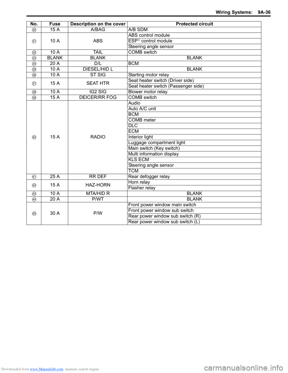
15 AA/BAG A/B SDM
10 A ABSABS control module
ESP
® control module
Steering angle sensor
10 A TAIL COMB switch
BLANK BLANK BLANK 20 A D/L BCM
10 A DIESEL/HID L BLANK
10 A ST SIG Starting motor relay
15 A SEAT HTR Seat heater switch (Driver side)
Seat heater switch (Passenger side)
10 A IG2 SIG Blower motor relay
15 A DEICER/RR FOG COMB switch
15 A RADIO Audio
Auto A/C unit
BCM
COMB meter
DLC
ECM
Interior light
Luggage compartment light
Main switch (Key switch)
Multi information display
KLS ECM
Steering angle sensor
TCM
25 A RR DEF Rear defogger relay
15 A HAZ-HORN Horn relay
Flasher relay
10 A MTA/HID R BLANK
20 A P/WT BLANK
30 A P/W Front power window main switch
Front power window sub switch
Rear power window sub switch (R)
Rear power window sub switch (L)
No. Fuse Description on the cover Protected circuit
Page 1329 of 1496

Downloaded from www.Manualslib.com manuals search engine Glass / Windows / Mirrors: 9E-2
• Eyeleteer
• Piano string
• Windshield knife
• Brush for primer application (2 pcs)
•Knife
• Rubber sucker grip
• Sealant gun (for filling adhesive)
• Putty spatula (for correcting adhered parts)
Diagnostic Information and Procedures
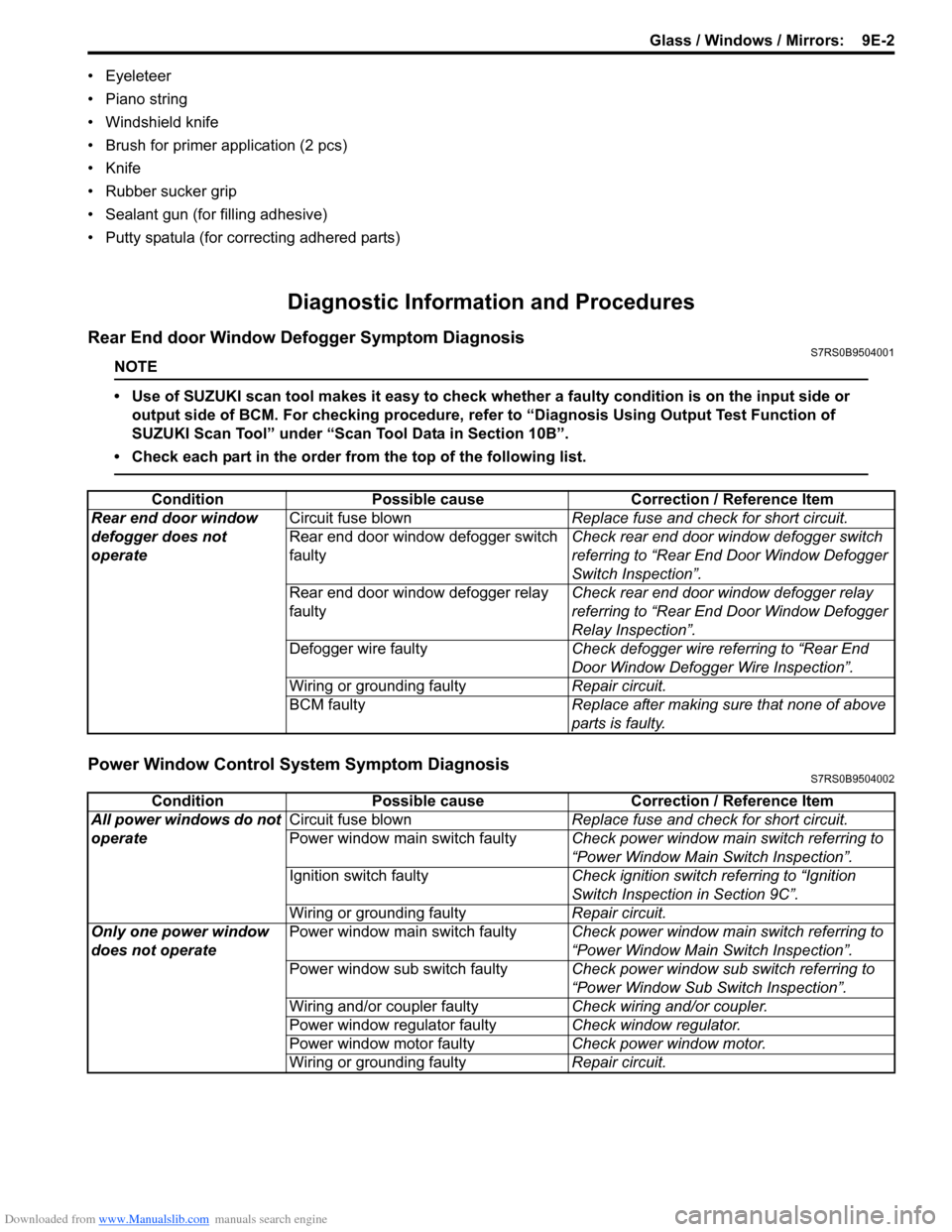
Rear End door Window Defogger Symptom DiagnosisS7RS0B9504001
NOTE
• Use of SUZUKI scan tool makes it easy to check whether a faulty condition is on the input side or
output side of BCM. For checking procedure, re fer to “Diagnosis Using Output Test Function of
SUZUKI Scan Tool” under “Scan Tool Data in Section 10B”.
• Check each part in the order from the top of the following list.
Power Window Control System Symptom DiagnosisS7RS0B9504002
Condition Possible cause Correction / Reference Item
Rear end door window
defogger does not
operate Circuit fuse blown
Replace fuse and check for short circuit.
Rear end door window defogger switch
faulty Check rear end door window defogger switch
referring to “Rear End Door Window Defogger
Switch Inspection”.
Rear end door window defogger relay
faulty Check rear end door window defogger relay
referring to “Rear End Door Window Defogger
Relay Inspection”.
Defogger wire faulty Check defogger wire referring to “Rear End
Door Window Defogger Wire Inspection”.
Wiring or grounding faulty Repair circuit.
BCM faulty Replace after making sure that none of above
parts is faulty.
ConditionPossible cause Correction / Reference Item
All power windows do not
operate Circuit fuse blown
Replace fuse and check for short circuit.
Power window main switch faulty Check power window main switch referring to
“Power Window Main Switch Inspection”.
Ignition switch faulty Check ignition switch referring to “Ignition
Switch Inspection in Section 9C”.
Wiring or grounding faulty Repair circuit.
Only one power window
does not operate Power window main switch faulty
Check power window main switch referring to
“Power Window Main Switch Inspection”.
Power window sub switch faulty Check power window sub switch referring to
“Power Window Sub Switch Inspection”.
Wiring and/or coupler faulty Check wiring and/or coupler.
Power window regulator faulty Check window regulator.
Power window motor faulty Check power window motor.
Wiring or grounding faulty Repair circuit.
Page 1330 of 1496

Downloaded from www.Manualslib.com manuals search engine 9E-3 Glass / Windows / Mirrors:
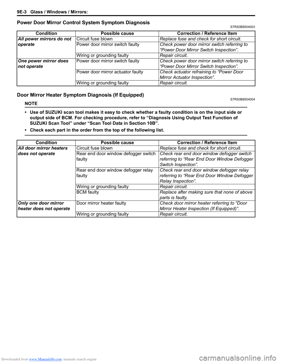
Power Door Mirror Control System Symptom DiagnosisS7RS0B9504003
Door Mirror Heater Symptom Diagnosis (If Equipped)S7RS0B9504004
NOTE
• Use of SUZUKI scan tool makes it easy to check whether a faulty condition is on the input side or
output side of BCM. For checking procedure, re fer to “Diagnosis Using Output Test Function of
SUZUKI Scan Tool” under “Scan Tool Data in Section 10B”.
• Check each part in the order from the top of the following list.
Condition Possible cause Correction / Reference Item
All power mirrors do not
operate Circuit fuse blown
Replace fuse and check for short circuit.
Power door mirror switch faulty Check power door mirror switch referring to
“Power Door Mirror Switch Inspection”.
Wiring or grounding faulty Repair circuit.
One power mirror does
not operate Power door mirror switch faulty
Check power door mirror switch referring to
“Power Door Mirror Switch Inspection”.
Power door mirror actuator faulty Check actuator refraining to “Power Door
Mirror Actuator Inspection”.
Wiring or grounding faulty Repair circuit.
ConditionPossible cause Correction / Reference Item
All door mirror heaters
does not operate Circuit fuse blown
Replace fuse and check for short circuit.
Rear end door window defogger switch
faulty Check rear end door window defogger switch
referring to “Rear End Door Window Defogger
Switch Inspection”.
Rear end door window defogger relay
faulty Check rear end door window defogger relay
referring to “Rear End Door Window Defogger
Relay Inspection”.
Wiring or grounding faulty Repair circuit.
BCM faulty Replace after making sure that none of above
parts is faulty.
Only one door mirror
heater does not operate Door mirror heater faulty
Check door mirror heater referring to “Door
Mirror Heater Inspection (If Equipped)”.
Wiring or grounding faulty Repair circuit.