2007 SUZUKI SWIFT ERROR
[x] Cancel search: ERRORPage 1454 of 1496
Downloaded from www.Manualslib.com manuals search engine 10C-11 Immobilizer Control System:
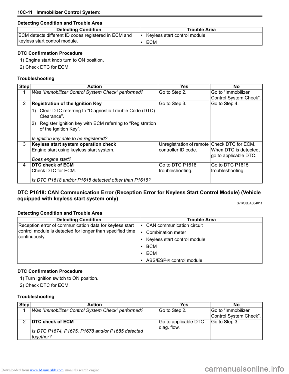
Detecting Condition and Trouble Area
DTC Confirmation Procedure1) Engine start knob turn to ON position.
2) Check DTC for ECM.
Troubleshooting
DTC P1618: CAN Communication Error (Reception Error for Keyless Start Control Module) (Vehicle
equipped with keyless start system only)
S7RS0BA304011
Detecting Condition and Trouble Area
DTC Confirmation Procedure 1) Turn Ignition switch to ON position.
2) Check DTC for ECM.
Troubleshooting Detecting Condition Trouble Area
ECM detects different ID codes registered in ECM and
keyless start control module. • Keyless start control module
•ECM
Step
Action YesNo
1 Was “Immobilizer Control S ystem Check” performed? Go to Step 2.Go to “Immobilizer
Control System Check”.
2 Registration of the Ignition Key
1) Clear DTC referring to “Diagnostic Trouble Code (DTC)
Clearance”.
2) Register ignition key with ECM referring to “Registration of the Ignition Key”.
Is ignition key able to be registered? Go to Step 3.
Go to Step 4.
3 Keyless start system operation check
Engine start using keyless start system.
Does engine start? Unregistration of remote
controller ID code.
Check DTC for ECM.
When DTC is detected,
go to applicable DTC.
4 DTC check of ECM
Check DTC for ECM.
Is DTC P1618 and/or P1615 detected other than P1616? Go to DTC P1618
troubleshooting.
Go to DTC P1615
troubleshooting.
Detecting Condition
Trouble Area
Reception error of communication data for keyless start
control module is detected for longer than specified time
continuously. • CAN communication circuit
• Combination meter
• Keyless start control module
•BCM
•ECM
• ABS/ESP®
control module
Step Action YesNo
1 Was “Immobilizer Control S ystem Check” performed? Go to Step 2.Go to “Immobilizer
Control System Check”.
2 DTC check of ECM
Is DTC P1674, P1675, P1678 and/or P1685 detected
together? Go to applicable DTC
diag. flow.
Go to Step 3.
Page 1455 of 1496
Downloaded from www.Manualslib.com manuals search engine Immobilizer Control System: 10C-12
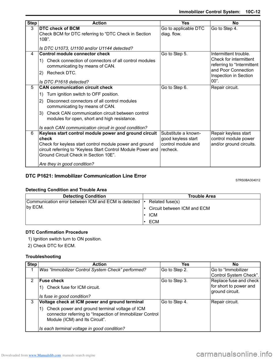
DTC P1621: Immobilizer Communication Line ErrorS7RS0BA304012
Detecting Condition and Trouble Area
DTC Confirmation Procedure1) Ignition switch turn to ON position.
2) Check DTC for ECM.
Troubleshooting 3
DTC check of BCM
Check BCM for DTC referring to “DTC Check in Section
10B”.
Is DTC U1073, U1100 and/or U1144 detected? Go to applicable DTC
diag. flow.
Go to Step 4.
4 Control module connector check
1) Check connection of connectors of all control modules
communicating by means of CAN.
2) Recheck DTC.
Is DTC P1618 detected? Go to Step 5. Intermittent trouble.
Check for intermittent
referring to “Intermittent
and Poor Connection
Inspection in Section
00”.
5 CAN communication circuit check
1) Turn ignition switch to OFF position.
2) Disconnect connectors of all control modules
communicating by means of CAN.
3) Check CAN communication circuit between control modules for open, short and high resistance.
Is each CAN communication circuit in good condition? Go to Step 6. Repair circuit.
6 Keyless start control module power and ground circuit
check
Check for keyless start control module power and ground
circuit referring to “Keyless St art Control Module Power and
Ground Circuit Check in Section 10E”.
Are they in good condition? Substitute a known-
good keyless start
control module and
recheck.
Repair keyless start
control module power
and/or ground circuits.
Step Action Yes No
Detecting Condition
Trouble Area
Communication error between ICM and ECM is detected
by ECM. • Related fuse(s)
• Circuit between ICM and ECM
•ICM
•ECM
Step
Action YesNo
1 Was “Immobilizer Control S ystem Check” performed? Go to Step 2.Go to “Immobilizer
Control System Check”.
2 Fuse check
1) Check fuse for ICM circuit.
Is fuse in good condition? Go to Step 3.
Replace fuse and check
for short to power and
ground circuit.
3 Voltage check at ICM power and ground terminal
1) Check power and ground terminal voltage of ICM
connector referring to “Inspe ction of Immobilizer Control
Module (ICM) and Its Circuit”.
Is each terminal voltage in good condition? Go to Step 4.
Repair circuit.
Page 1456 of 1496
Downloaded from www.Manualslib.com manuals search engine 10C-13 Immobilizer Control System:
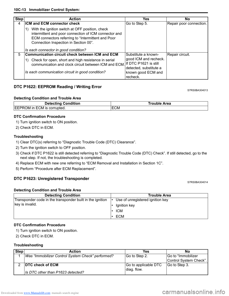
DTC P1622: EEPROM Reading / Writing ErrorS7RS0BA304013
Detecting Condition and Trouble Area
DTC Confirmation Procedure1) Turn ignition switch to ON position.
2) Check DTC in ECM.
Troubleshooting 1) Clear DTC(s) referring to “Diagnostic Trouble Code (DTC) Clearance”.
2) Turn the ignition switch to OFF position.
3) Check if DTC P1622 is still detected re ferring to “Diagnostic Trouble Code (DTC) Check”. If still detected, go to the
next step. If not, the troubleshooting is completed.
4) Replace ECM with new one referring to “ECM Removal and Installation in Section 1C”.
5) Perform “Procedure after ECM Replacement”.
DTC P1623: Unregistered TransponderS7RS0BA304014
Detecting Condition and Trouble Area
DTC Confirmation Procedure 1) Turn ignition switch to ON position.
2) Check DTC in ECM.
Troubleshooting 4
ICM and ECM connector check
1) With the ignition switch at OFF position, check
intermittent and poor connec tion of ICM connector and
ECM connectors referring to “Intermittent and Poor
Connection Inspection in Section 00”.
Is each connector in good condition? Go to Step 5. Repair poor connection.
5 Communication circuit check between ICM and ECM
1) Check for open, short and high resistance in serial
communication and clock circuit between ICM and ECM.
Is each communication circuit in good condition? Substitute a known-
good ICM and recheck.
If DTC P1621 is still
detected, substitute a
known good ECM and
recheck.Repair circuit.
Step Action Yes No
Detecting Condition
Trouble Area
EEPROM in ECM is corrupted. ECM
Detecting Condition Trouble Area
Transponder code in the transponder built in the ignition
key is invalid. • Use of unregistered ignition key
• Ignition key
•ICM
•ECM
Step
Action YesNo
1 Was “Immobilizer Control S ystem Check” performed? Go to Step 2.Go to “Immobilizer
Control System Check”.
2 DTC check of ECM
Is DTC other than P1623 detected? Go to applicable DTC
diag. flow.
Go to Step 3.
Page 1457 of 1496
Downloaded from www.Manualslib.com manuals search engine Immobilizer Control System: 10C-14
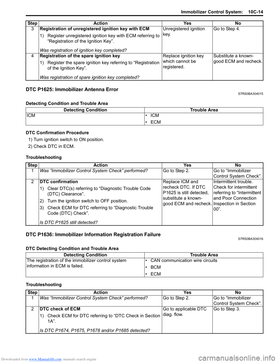
DTC P1625: Immobilizer Antenna ErrorS7RS0BA304015
Detecting Condition and Trouble Area
DTC Confirmation Procedure1) Turn ignition switch to ON position.
2) Check DTC in ECM.
Troubleshooting
DTC P1636: Immobilizer Information Registration FailureS7RS0BA304016
DTC Detecting Condition and Trouble Area
Troubleshooting 3
Registration of unregistered ignition key with ECM
1) Register unregistered igniti on key with ECM referring to
“Registration of the Ignition Key”.
Was registration of ignition key completed? Unregistered ignition
key.
Go to Step 4.
4 Registration of the spare ignition key
1) Register the spare ignition key referring to “Registration
of the Ignition Key”.
Was registration of spare ignition key completed? Replace ignition key
which cannot be
registered.
Substitute a known-
good ECM and recheck.
Step Action Yes No
Detecting Condition
Trouble Area
ICM • ICM
•ECM
StepAction YesNo
1 Was “Immobilizer Control S ystem Check” performed? Go to Step 2.Go to “Immobilizer
Control System Check”.
2 DTC confirmation
1) Clear DTC(s) referring to “Diagnostic Trouble Code
(DTC) Clearance”.
2) Turn the ignition switch to OFF position.
3) Check ECM for DTC referring to “Diagnostic Trouble Code (DTC) Check”.
Is DTC P1625 still detected? Replace ICM and
recheck DTC. If DTC
P1625 is still detected,
substitute a known-
good ECM and recheck.
Intermittent trouble.
Check for intermittent
referring to “Intermittent
and Poor Connection
Inspection in Section
00”.
Detecting Condition
Trouble Area
The registration of the immobilizer control system
information in ECM is failed. • CAN communication wire circuits
•BCM
•ECM
Step
Action YesNo
1 Was “Immobilizer Control S ystem Check” performed? Go to Step 2.Go to “Immobilizer
Control System Check”.
2 DTC check of ECM
1) Check ECM for DTC referring to “DTC Check in Section
1A”.
Is DTC P1674, P1675, P1678 and/or P1685 detected? Go to applicable DTC
diag. flow.
Go to Step 3.
Page 1473 of 1496
Downloaded from www.Manualslib.com manuals search engine Keyless Start System: 10E-11
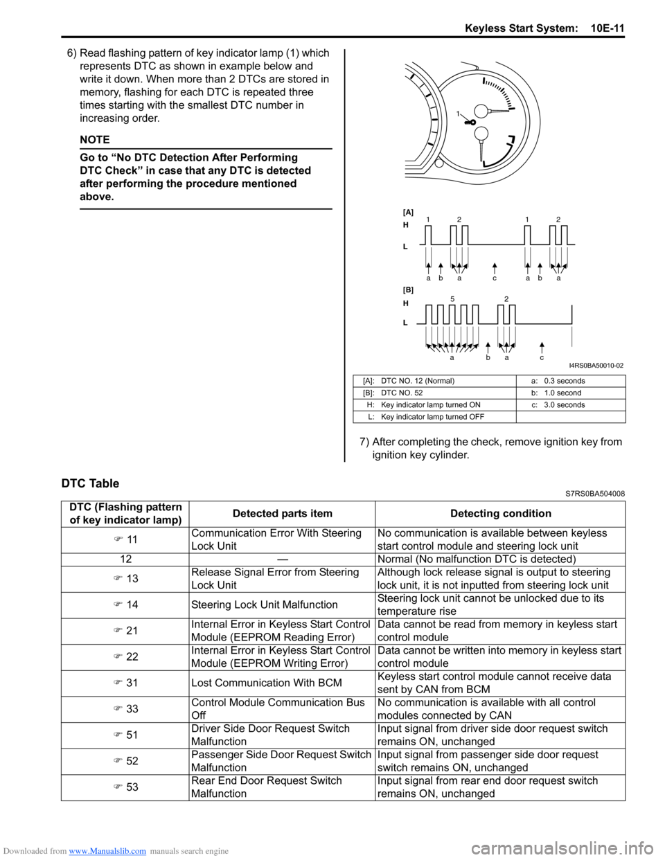
6) Read flashing pattern of key indicator lamp (1) which represents DTC as shown in example below and
write it down. When more than 2 DTCs are stored in
memory, flashing for each DTC is repeated three
times starting with the smallest DTC number in
increasing order.
NOTE
Go to “No DTC Detect ion After Performing
DTC Check” in case that any DTC is detected
after performing the procedure mentioned
above.
7) After completing the check, remove ignition key from ignition key cylinder.
DTC TableS7RS0BA504008
[A]: DTC NO. 12 (Normal)
a: 0.3 seconds
[B]: DTC NO. 52 b: 1.0 second
H: Key indicator lamp tu rned ONc: 3.0 seconds
L: Key indicator lamp turned OFF
bc
a
a
[A]
H
L
H
L [B]
52
bac
a
2
11baa 2
1
I4RS0BA50010-02
DTC (Flashing pattern
of key indicator lamp) Detected parts item Detecting condition
�) 11 Communication Error With Steering
Lock Unit No communication is available between keyless
start control module and steering lock unit
12 — Normal (No malfunct ion DTC is detected)
�) 13 Release Signal Error from Steering
Lock Unit Although lock release signal is output to steering
lock unit, it is not inputt
ed from steering lock unit
�) 14 Steering Lock Unit Malfunction Steering lock unit cannot be unlocked due to its
temperature rise
�) 21 Internal Error in Ke
yless Start Control
Module (EEPROM Reading Error) Data cannot be read from memory in keyless start
control module
�) 22 Internal Error in Ke
yless Start Control
Module (EEPROM Writing Error) Data cannot be written into memory in keyless start
control module
�) 31 Lost Communication With BCM Keyless start control module cannot receive data
sent by CAN from BCM
�) 33 Control Module Communication Bus
Off No communication is available with all control
modules connected by CAN
�) 51 Driver Side Door Request Switch
Malfunction Input signal from driver side door request switch
remains ON, unchanged
�) 52 Passenger Side Door Request Switch
Malfunction Input signal from passenger side door request
switch remains ON, unchanged
�) 53 Rear End Door Request Switch
Malfunction Input signal from rear end door request switch
remains ON, unchanged
Page 1485 of 1496
Downloaded from www.Manualslib.com manuals search engine Keyless Start System: 10E-23
DTC No. 11: Communication Error with Steering Lock UnitS7RS0BA504017
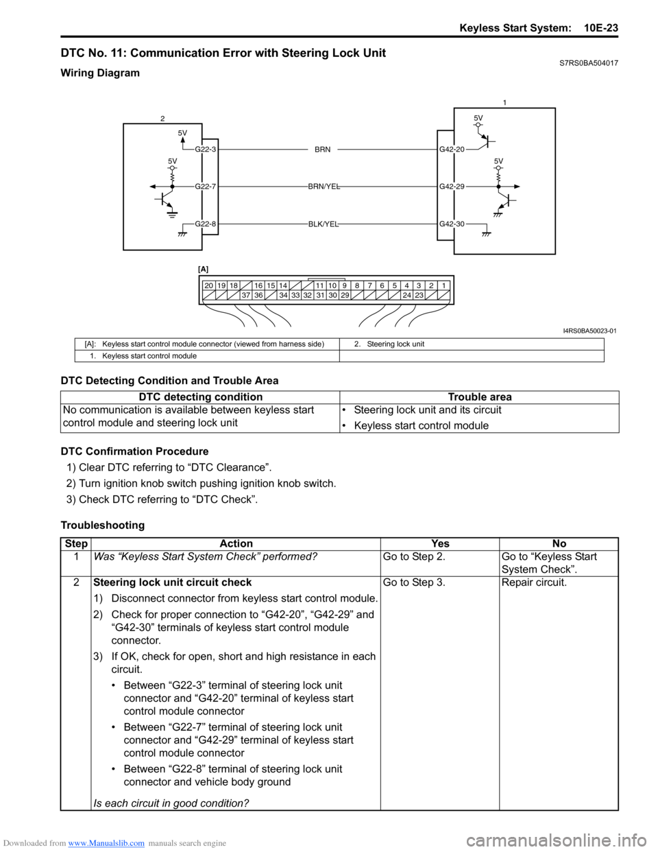
Wiring Diagram
DTC Detecting Condition and Trouble Area
DTC Confirmation Procedure1) Clear DTC referring to “DTC Clearance”.
2) Turn ignition knob switch pushing ignition knob switch.
3) Check DTC referring to “DTC Check”.
Troubleshooting
5V
G42-20
G42-29
G42-30
G22-3
G22-7
G22-8
1234567891011
141516
36 34 33 32 31 30 29 24 23
37
181920
5V
5V
BRN
BRN/YEL
BLK/YEL
5V
2 1
[A]
I4RS0BA50023-01
[A]: Keyless start control module connector (vie wed from harness side) 2. Steering lock unit
1. Keyless start control module
DTC detecting condition Trouble area
No communication is available between keyless start
control module and steering lock unit • Steering lock unit and its circuit
• Keyless start control module
Step
Action YesNo
1 Was “Keyless Start System Check” performed? Go to Step 2.Go to “Keyless Start
System Check”.
2 Steering lock unit circuit check
1) Disconnect connector from keyless start control module.
2) Check for proper connection to “G42-20”, “G42-29” and
“G42-30” terminals of keyless start control module
connector.
3) If OK, check for open, short and high resistance in each circuit.
• Between “G22-3” terminal of steering lock unit connector and “G42-20” terminal of keyless start
control module connector
• Between “G22-7” terminal of steering lock unit connector and “G42-29” terminal of keyless start
control module connector
• Between “G22-8” terminal of steering lock unit connector and vehicle body ground
Is each circuit in good condition? Go to Step 3.
Repair circuit.
Page 1486 of 1496
Downloaded from www.Manualslib.com manuals search engine 10E-24 Keyless Start System:
DTC No. 13 / No. 14: Release Signal Error from Steering Lock Unit / Steering Lock Unit MalfunctionS7RS0BA504018
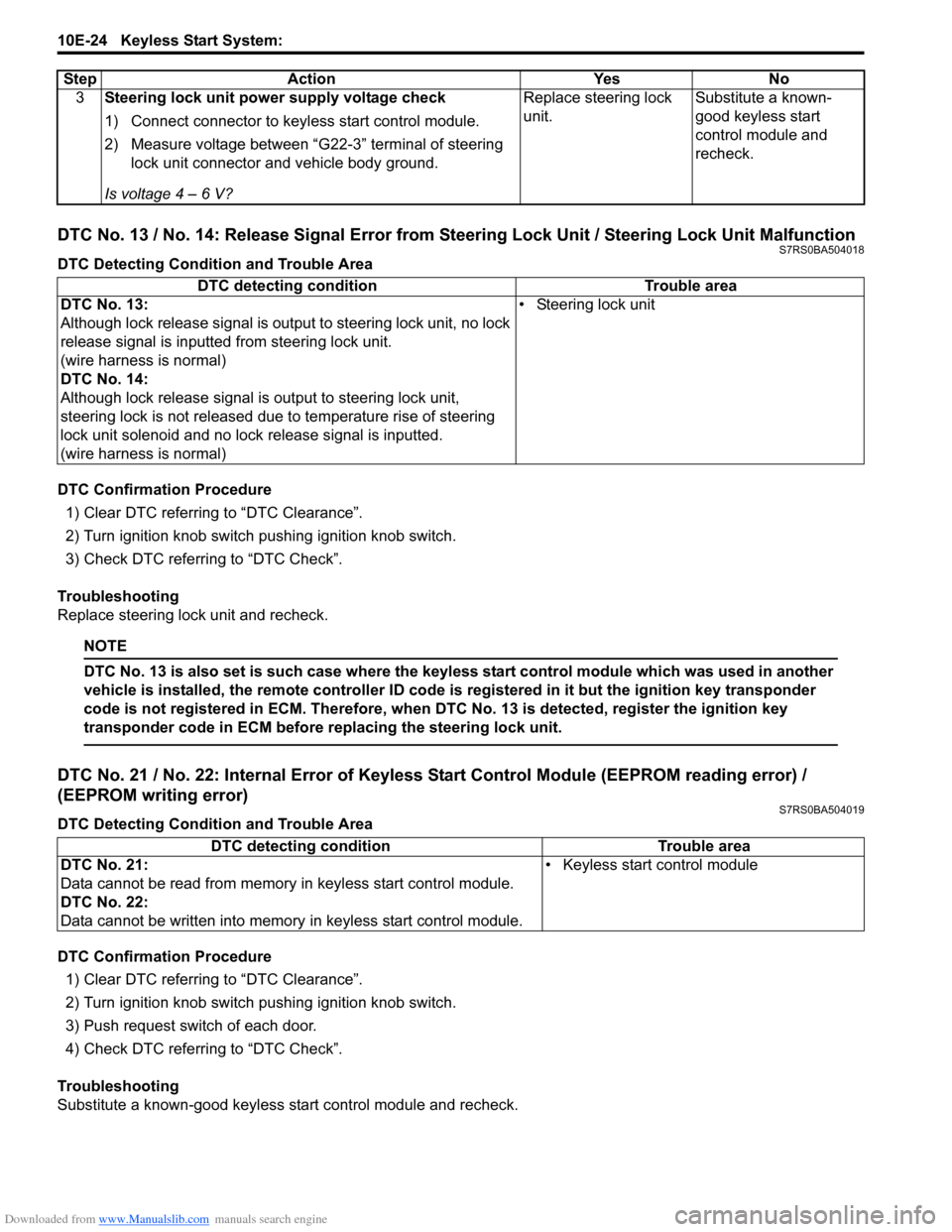
DTC Detecting Condition and Trouble Area
DTC Confirmation Procedure1) Clear DTC referring to “DTC Clearance”.
2) Turn ignition knob switch pushing ignition knob switch.
3) Check DTC referring to “DTC Check”.
Troubleshooting
Replace steering lock unit and recheck.
NOTE
DTC No. 13 is also set is such case where the keyless start control module which was used in another
vehicle is installed, the remote controller ID code is registered in it but the ignition key transponder
code is not registered in ECM. Therefore, when DTC No. 13 is detected, register the ignition key
transponder code in ECM before replacing the steering lock unit.
DTC No. 21 / No. 22: Internal Error of Keyle ss Start Control Module (EEPROM reading error) /
(EEPROM writing error)
S7RS0BA504019
DTC Detecting Condition and Trouble Area
DTC Confirmation Procedure
1) Clear DTC referring to “DTC Clearance”.
2) Turn ignition knob switch pushing ignition knob switch.
3) Push request switch of each door.
4) Check DTC referring to “DTC Check”.
Troubleshooting
Substitute a known-good keyless start control module and recheck. 3
Steering lock unit power supply voltage check
1) Connect connector to keyl ess start control module.
2) Measure voltage between “G22-3” terminal of steering lock unit connector and vehicle body ground.
Is voltage 4 – 6 V? Replace steering lock
unit.
Substitute a known-
good keyless start
control module and
recheck.
Step Action Yes No
DTC detecting condition
Trouble area
DTC No. 13:
Although lock release signal is ou tput to steering lock unit, no lock
release signal is inputted from steering lock unit.
(wire harness is normal)
DTC No. 14:
Although lock release signal is output to steering lock unit,
steering lock is not released due to temperature rise of steering
lock unit solenoid and no lock release signal is inputted.
(wire harness is normal) • Steering lock unit
DTC detecting condition Trouble area
DTC No. 21:
Data cannot be read from memory in keyless start control module.
DTC No. 22:
Data cannot be written into memory in keyless start control module.• Keyless start control module