2007 SUZUKI SWIFT ERROR
[x] Cancel search: ERRORPage 1417 of 1496
Downloaded from www.Manualslib.com manuals search engine Body Electrical Control System: 10B-14
DTC TableS7RS0BA204004
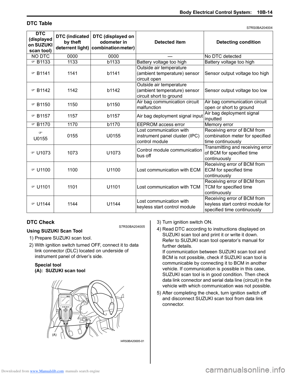
DTC CheckS7RS0BA204005
Using SUZUKI Scan Tool1) Prepare SUZUKI scan tool.
2) With ignition switch turned OFF, connect it to data link connector (DLC) located on underside of
instrument panel of driver’s side.
Special tool
(A): SUZUKI scan tool 3) Turn ignition switch ON.
4) Read DTC according to
instructions displayed on
SUZUKI scan tool and print it or write it down.
Refer to SUZUKI scan tool operator’s manual for
further details.
If communication between SUZUKI scan tool and
BCM is not possible, check if SUZUKI scan tool is
communicable by connecting it to BCM in another
vehicle. If communication is possible in this case,
SUZUKI scan tool is in good condition. Then check
data link connector and serial data line (circuit) in the
vehicle with which communica tion was not possible.
5) After completing the check, turn ignition switch off and disconnect SUZUKI scan tool from data link
connector.
DTC
(displayed
on SUZUKI scan tool) DTC (indicated
by theft
deterrent light) DTC (displayed on
odometer in
combination meter) Detected item Detecting condition
NO DTC 0000 0000 — No DTC detected
�) B1133 1133 b1133 Battery voltage too high Battery voltage too high
�) B1141 1141 b1141 Outside air temperature
(ambient temperature) sensor
circuit openSensor output voltage too high
�) B1142 1142 b1142 Outside air temperature
(ambient temperature) sensor
circuit short to groundSensor output voltage too low
�) B1150 1150 b1150 Air bag communication circuit
malfunctionAir bag communication circuit
open or short to ground
�) B1157 1157 b1157 Air bag deployment signal input Air bag deployment signal
inputted
�) B1170 1170 b1170 EEPROM access error Memory error
�)
U0155 0155 U0155 Lost communication with
instrument panel cluster (IPC)
control moduleReceiving error of BCM from
combination mete
r for specified
time continuously
�) U1073 1073 U1073 Control module communication
bus offTransmitting and receiving error
of BCM for specified time
continuously
�) U1100 1100 U1100 Lost communication with ECM Receiving error of BCM from
ECM for specified time
continuously
�) U1101 1101 U1101 Lost communication with TCM Receiving error of BCM from
TCM for specified time
continuously
�) U1144 1144 U1144 Lost communication with
keyless start control moduleReceiving error of BCM from
keyless start control module for
specified time continuously
(A)
I4RS0BA20005-01
Page 1424 of 1496
Downloaded from www.Manualslib.com manuals search engine 10B-21 Body Electrical Control System:
DTC B1170 (No. 1170): EEPROM Access ErrorS7RS0BA204012
DTC Detecting Condition and Possible Cause
DTC Troubleshooting
NOTE
Before performing steps below, be sure to perform “Body Electrical Control System Check”.
1) Ignition switch OFF.
2) Replace BCM.
3) Repeat BCM Check Flow Table.
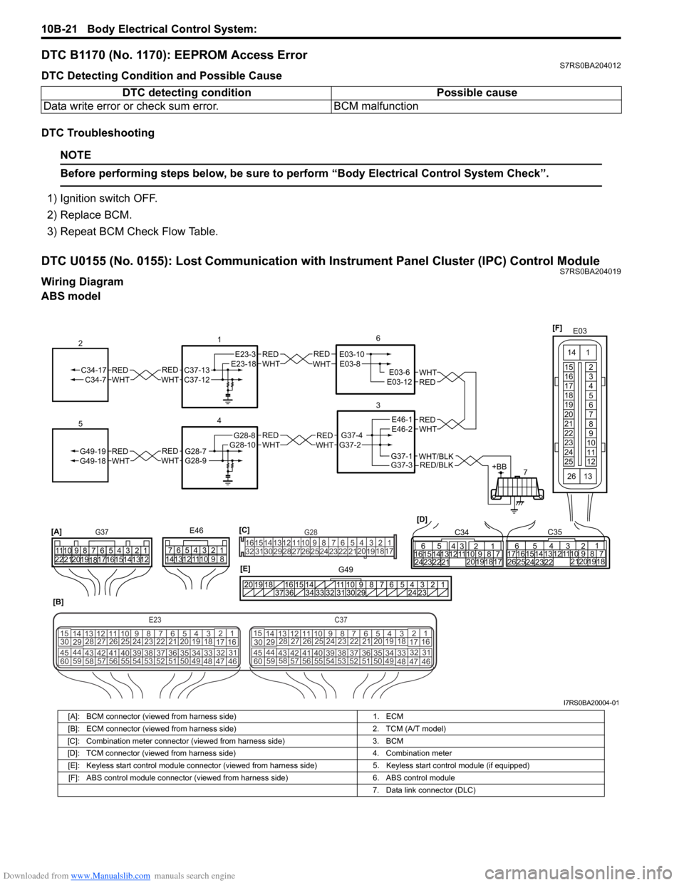
DTC U0155 (No. 0155): Lost Communication with Instrument Panel Cluster (IPC) Control ModuleS7RS0BA204019
Wiring Diagram
ABS model DTC detecting condition Possible cause
Data write error or check sum error. BCM malfunction
REDWHTE03-6E03-12
6
3
7
REDWHT
1
[B]
[A]
G37E46
1234567
1234567
8910
11
8910
11
121314 121314
151617
18
19202122 [D]65
1615 141312 11 43
2423 2122 10 9 8 7
21
1920 1817
C3417 16
26 2515 14
65 3
42
13 12
23 2224 1110 9
212019 87
18
1
C35
[E]
REDWHTC37-13C37-12REDWHTC34-17C34-7
2
12345678910
11
141516
36 34 33 32 31 30 29 24 23
37
181920
[C] [F]
G49
E23-3E23-18
4
REDWHTG28-7G28-9REDWHTG49-19G49-18
5
REDWHTE03-10E03-8
G37-4G37-2
REDWHTE46-1E46-2REDWHTREDWHTG28-8G28-10
E03
15
16
17
18
19
20
21
22
23
24
25 2
3
4
5
6
7
8
9
10
11
12
1
13
14
26
E23C37
34
1819
567
1011
17
20
47 46
495051
2122
52 16
25 9
24
14
29
5557 54 53
59
60 58 2
262728
15
30
56 4832 31
34353637
4042 39 38
44
45 43 41 33 1
1213
238
34
1819
567
1011
17
20
47 46
495051
2122
52 16
25 9
24
14
29
5557 54 53
59
60 58 2
262728
15
30
56 4832 31
34353637
4042 39 38
44
45 43 41 331
1213
238
G281234567
8
910111213141516
1718
19
20
212223242526272829303132
RED/BLKWHT/BLKG37-3G37-1+BB
I7RS0BA20004-01
[A]: BCM connector (viewed from harness side) 1. ECM
[B]: ECM connector (viewed from harness side) 2. TCM (A/T model)
[C]: Combination meter connector (viewed from harness side) 3. BCM
[D]: TCM connector (viewed from harness side) 4. Combination meter
[E]: Keyless start control module connector (viewed from harness side) 5. Keyless start control module (if equipped)
[F]: ABS control module connector (viewed from harness side) 6. ABS control module
7. Data link connector (DLC)
Page 1427 of 1496
Downloaded from www.Manualslib.com manuals search engine Body Electrical Control System: 10B-24
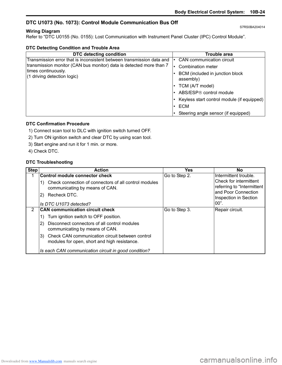
DTC U1073 (No. 1073): Control Module Communication Bus OffS7RS0BA204014
Wiring Diagram
Refer to “DTC U0155 (No. 0155): Lost Communication with Instrument Panel Cluster (IPC) Control Module”.
DTC Detecting Condition and Trouble Area
DTC Confirmation Procedure 1) Connect scan tool to DLC with ignition switch turned OFF.
2) Turn ON ignition switch and clear DTC by using scan tool.
3) Start engine and run it for 1 min. or more.
4) Check DTC.
DTC Troubleshooting DTC detecting condition Trouble area
Transmission error that is inconsistent between transmission data and
transmission monitor (CAN bus monitor) data is detected more than 7
times continuously.
(1 driving detection logic) • CAN communication circuit
• Combination meter
• BCM (included in junction block
assembly)
• TCM (A/T model)
• ABS/ESP ® control module
• Keyless start control module (if equipped)
•ECM
• Steering angle sensor (if equipped)
Step Action YesNo
1 Control module connector check
1) Check connection of connectors of all control modules
communicating by means of CAN.
2) Recheck DTC.
Is DTC U1073 detected? Go to Step 2.
Intermittent trouble.
Check for intermittent
referring to “Intermittent
and Poor Connection
Inspection in Section
00”.
2 CAN communication circuit check
1) Turn ignition switch to OFF position.
2) Disconnect connectors of all control modules
communicating by means of CAN.
3) Check CAN communication circuit between control modules for open, short and high resistance.
Is each CAN communication circuit in good condition? Go to Step 3.
Repair circuit.
Page 1429 of 1496
Downloaded from www.Manualslib.com manuals search engine Body Electrical Control System: 10B-26
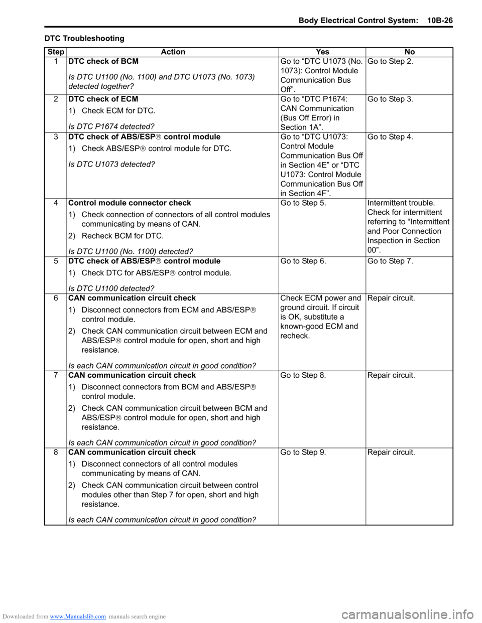
DTC TroubleshootingStep Action Yes No 1 DTC check of BCM
Is DTC U1100 (No. 1100) and DTC U1073 (No. 1073)
detected together? Go to “DTC U1073 (No.
1073): Control Module
Communication Bus
Off”.Go to Step 2.
2 DTC check of ECM
1) Check ECM for DTC.
Is DTC P1674 detected? Go to “DTC P1674:
CAN Communication
(Bus Off Error) in
Section 1A”.Go to Step 3.
3 DTC check of ABS/ESP ® control module
1) Check ABS/ESP ® control module for DTC.
Is DTC U1073 detected? Go to “DTC U1073:
Control Module
Communication Bus Off
in Section 4E” or “DTC
U1073: Control Module
Communication Bus Off
in Section 4F”.Go to Step 4.
4 Control module connector check
1) Check connection of connectors of all control modules
communicating by means of CAN.
2) Recheck BCM for DTC.
Is DTC U1100 (No. 1100) detected? Go to Step 5. Intermittent trouble.
Check for intermittent
referring to “Intermittent
and Poor Connection
Inspection in Section
00”.
5 DTC check of ABS/ESP ® control module
1) Check DTC for ABS/ESP ® control module.
Is DTC U1100 detected? Go to Step 6. Go to Step 7.
6 CAN communication circuit check
1) Disconnect connector s from ECM and ABS/ESP ®
control module.
2) Check CAN communication circuit between ECM and ABS/ESP ® control module for open, short and high
resistance.
Is each CAN communication circuit in good condition? Check ECM power and
ground circuit. If circuit
is OK, substitute a
known-good ECM and
recheck.
Repair circuit.
7 CAN communication circuit check
1) Disconnect connector s from BCM and ABS/ESP ®
control module.
2) Check CAN communication circuit between BCM and ABS/ESP ® control module for open, short and high
resistance.
Is each CAN communication circuit in good condition? Go to Step 8. Repair circuit.
8 CAN communication circuit check
1) Disconnect connectors of all control modules
communicating by means of CAN.
2) Check CAN communication circuit between control modules other than Step 7 for open, short and high
resistance.
Is each CAN communication circuit in good condition? Go to Step 9. Repair circuit.
Page 1430 of 1496
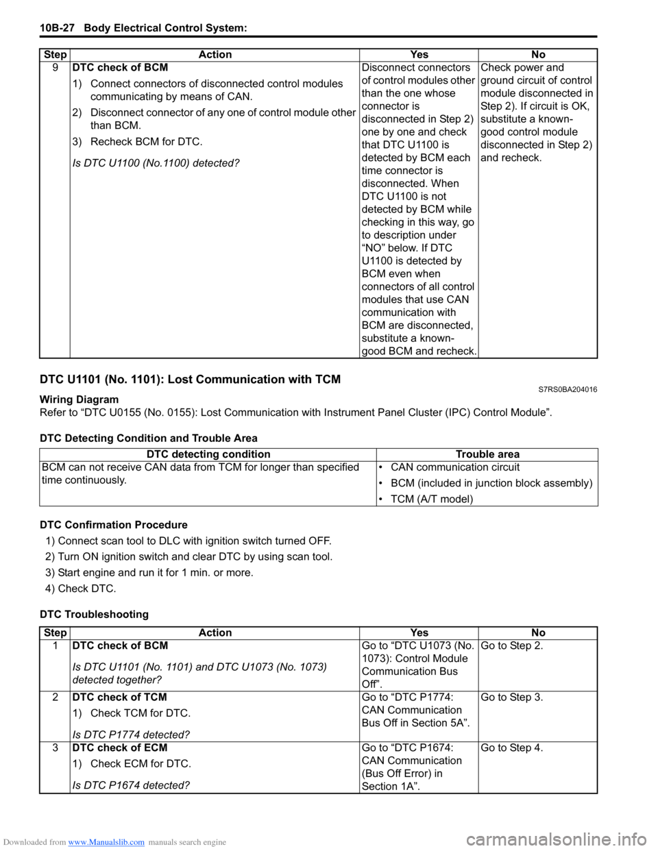
Downloaded from www.Manualslib.com manuals search engine 10B-27 Body Electrical Control System:
DTC U1101 (No. 1101): Lost Communication with TCMS7RS0BA204016
Wiring Diagram
Refer to “DTC U0155 (No. 0155): Lost Communication with Instrument Panel Cluster (IPC) Control Module”.
DTC Detecting Condition and Trouble Area
DTC Confirmation Procedure 1) Connect scan tool to DLC with ignition switch turned OFF.
2) Turn ON ignition switch and clear DTC by using scan tool.
3) Start engine and run it for 1 min. or more.
4) Check DTC.
DTC Troubleshooting 9
DTC check of BCM
1) Connect connectors of disconnected control modules
communicating by means of CAN.
2) Disconnect connector of any one of control module other than BCM.
3) Recheck BCM for DTC.
Is DTC U1100 (No.1100) detected? Disconnect connectors
of control modules other
than the one whose
connector is
disconnected in Step 2)
one by one and check
that DTC U1100 is
detected by BCM each
time connector is
disconnected. When
DTC U1100 is not
detected by BCM while
checking in this way, go
to description under
“NO” below. If DTC
U1100 is detected by
BCM even when
connectors of all control
modules that use CAN
communication with
BCM are disconnected,
substitute a known-
good BCM and recheck.Check power and
ground circuit of control
module disconnected in
Step 2). If circuit is OK,
substitute a known-
good control module
disconnected in Step 2)
and recheck.
Step Action Yes No
DTC detecting condition
Trouble area
BCM can not receive CAN data from TCM for longer than specified
time continuously. • CAN communication circuit
• BCM (included in junction block assembly)
• TCM (A/T model)
Step
Action YesNo
1 DTC check of BCM
Is DTC U1101 (No. 1101) and DTC U1073 (No. 1073)
detected together? Go to “DTC U1073 (No.
1073): Control Module
Communication Bus
Off”.Go to Step 2.
2 DTC check of TCM
1) Check TCM for DTC.
Is DTC P1774 detected? Go to “DTC P1774:
CAN Communication
Bus Off in Section 5A”.
Go to Step 3.
3 DTC check of ECM
1) Check ECM for DTC.
Is DTC P1674 detected? Go to “DTC P1674:
CAN Communication
(Bus Off Error) in
Section 1A”.Go to Step 4.
Page 1449 of 1496
Downloaded from www.Manualslib.com manuals search engine Immobilizer Control System: 10C-6
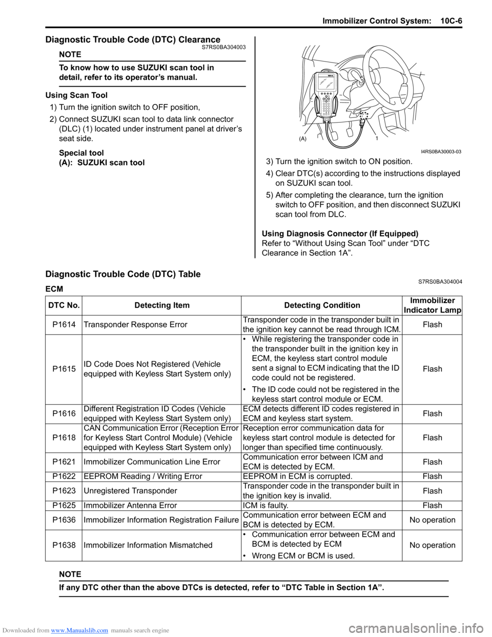
Diagnostic Trouble Code (DTC) ClearanceS7RS0BA304003
NOTE
To know how to use SUZUKI scan tool in
detail, refer to its operator’s manual.
Using Scan Tool
1) Turn the ignition switch to OFF position,
2) Connect SUZUKI scan tool to data link connector (DLC) (1) located under instrument panel at driver’s
seat side.
Special tool
(A): SUZUKI scan tool 3) Turn the ignition switch to ON position.
4) Clear DTC(s) according to the instructions displayed
on SUZUKI scan tool.
5) After completing the clearance, turn the ignition switch to OFF position, and then disconnect SUZUKI
scan tool from DLC.
Using Diagnosis Connector (If Equipped)
Refer to “Without Using Scan Tool” under “DTC
Clearance in Section 1A”.
Diagnostic Trouble Code (DTC) TableS7RS0BA304004
ECM
NOTE
If any DTC other than the above DTCs is detected, refer to “DTC Table in Section 1A”.
(A)1
I4RS0BA30003-03
DTC No. Detecting Item Detecting ConditionImmobilizer
Indicator Lamp
P1614 Transponder Response Error Transponder code in the transponder built in
the ignition key cannot be read through ICM.Flash
P1615 ID Code Does Not Re
gistered (Vehicle
equipped with Keyless Start System only) • While registering the transponder code in
the transponder built in the ignition key in
ECM, the keyless start control module
sent a signal to ECM indicating that the ID
code could not be registered.
• The ID code could not be registered in the keyless start control module or ECM. Flash
P1616 Different Registration ID Codes (Vehicle
equipped with Keyless Start System only) ECM detects different ID codes registered in
ECM and keyless start system.
Flash
P1618 CAN Communication Error (Reception Error
for Keyless Start Control Module) (Vehicle
equipped with Keyless Start System only) Reception error communication data for
keyless start control module is detected for
longer than specified time continuously.
Flash
P1621 Immobilizer Commu nication Line ErrorCommunication error between ICM and
ECM is detected by ECM. Flash
P1622 EEPROM Reading / Writing Error EEPROM in ECM is corrupted.Flash
P1623 Unregistered Transponder Transponder code in the transponder built in
the ignition key is invalid.Flash
P1625 Immobilizer Antenna Error ICM is faulty.Flash
P1636 Immobilizer Information Registration Failure Communication error between ECM and
BCM is detected by ECM.No operation
P1638 Immobilizer Info rmation Mismatched • Communication error between ECM and
BCM is detected by ECM
• Wrong ECM or BCM is used. No operation
Page 1452 of 1496
Downloaded from www.Manualslib.com manuals search engine 10C-9 Immobilizer Control System:
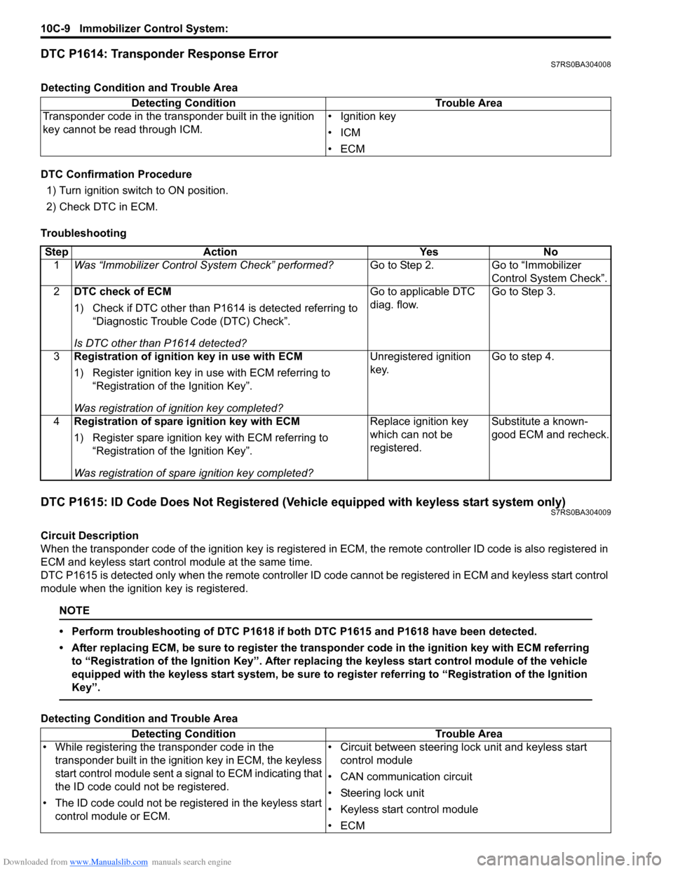
DTC P1614: Transponder Response ErrorS7RS0BA304008
Detecting Condition and Trouble Area
DTC Confirmation Procedure
1) Turn ignition switch to ON position.
2) Check DTC in ECM.
Troubleshooting
DTC P1615: ID Code Does Not Registered (Vehicle equipped with keyless start system only)S7RS0BA304009
Circuit Description
When the transponder code of the ignition key is registered in ECM, the remote controller ID code is also registered in
ECM and keyless start contro l module at the same time.
DTC P1615 is detected only when the remote controller ID code cannot be registered in ECM and keyless start control
module when the ignition key is registered.
NOTE
• Perform troubleshooting of DTC P1618 if both DTC P1615 and P1618 have been detected.
• After replacing ECM, be sure to register the tran sponder code in the ignition key with ECM referring
to “Registration of the Ignition Key”. After replac ing the keyless start control module of the vehicle
equipped with the keyless start system, be sure to register referring to “Registration of the Ignition
Key”.
Detecting Condition and Trouble Area Detecting Condition Trouble Area
Transponder code in the transponder built in the ignition
key cannot be read through ICM. • Ignition key
•ICM
•ECM
Step
Action YesNo
1 Was “Immobilizer Control S ystem Check” performed? Go to Step 2.Go to “Immobilizer
Control System Check”.
2 DTC check of ECM
1) Check if DTC other than P1614 is detected referring to
“Diagnostic Trouble Code (DTC) Check”.
Is DTC other than P1614 detected? Go to applicable DTC
diag. flow.
Go to Step 3.
3 Registration of ignition key in use with ECM
1) Register ignition key in use with ECM referring to
“Registration of the Ignition Key”.
Was registration of ignition key completed? Unregistered ignition
key.
Go to step 4.
4 Registration of spare ignition key with ECM
1) Register spare ignition key with ECM referring to
“Registration of the Ignition Key”.
Was registration of spare ignition key completed? Replace ignition key
which can not be
registered.
Substitute a known-
good ECM and recheck.
Detecting Condition
Trouble Area
• While registering the transponder code in the transponder built in the ignition key in ECM, the keyless
start control module sent a signal to ECM indicating that
the ID code could not be registered.
• The ID code could not be registered in the keyless start control module or ECM. • Circuit between steering lo
ck unit and keyless start
control module
• CAN communication circuit
• Steering lock unit
• Keyless start control module
•ECM
Page 1453 of 1496
Downloaded from www.Manualslib.com manuals search engine Immobilizer Control System: 10C-10
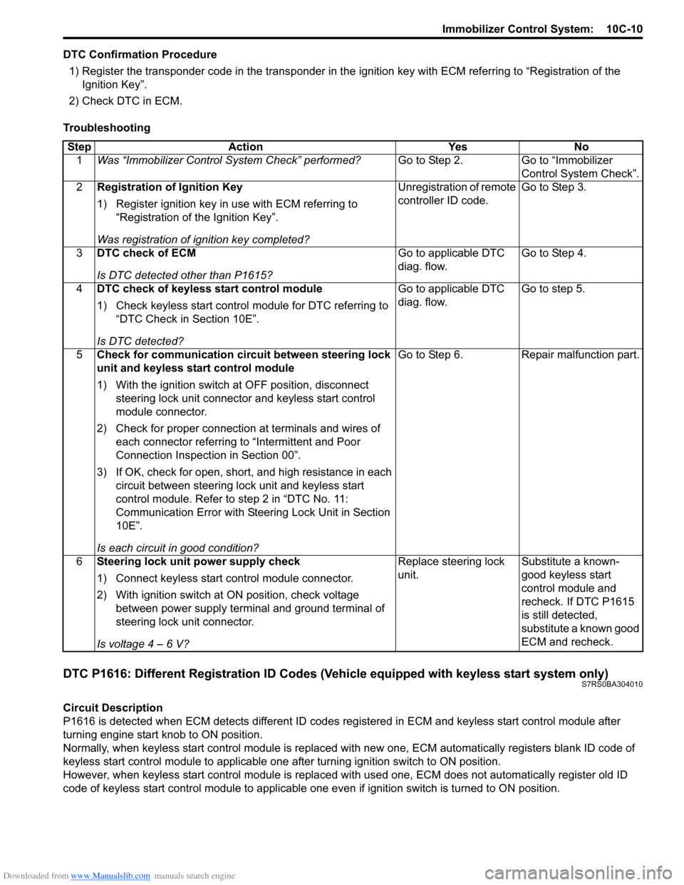
DTC Confirmation Procedure1) Register the transponder code in the transponder in the ignition key with ECM referring to “Registration of the
Ignition Key”.
2) Check DTC in ECM.
Troubleshooting
DTC P1616: Different Registration ID Codes (Vehicle equipped with keyless start system only)S7RS0BA304010
Circuit Description
P1616 is detected when ECM detects different ID codes registered in ECM and keyless start control module after
turning engine start knob to ON position.
Normally, when keyless start control module is replaced with new one, ECM automatically registers blank ID code of
keyless start control module to applicable one after turning ignition switch to ON position.
However, when keyless start control module is replaced wit h used one, ECM does not automatically register old ID
code of keyless start control module to applicable one ev en if ignition switch is turned to ON position.
Step Action Yes No
1 Was “Immobilizer Control S ystem Check” performed? Go to Step 2. Go to “Immobilizer
Control System Check”.
2 Registration of Ignition Key
1) Register ignition key in use with ECM referring to
“Registration of the Ignition Key”.
Was registration of ignition key completed? Unregistration of remote
controller ID code.
Go to Step 3.
3 DTC check of ECM
Is DTC detected other than P1615? Go to applicable DTC
diag. flow.
Go to Step 4.
4 DTC check of keyless start control module
1) Check keyless start control module for DTC referring to
“DTC Check in Section 10E”.
Is DTC detected? Go to applicable DTC
diag. flow.
Go to step 5.
5 Check for communication circuit between steering lock
unit and keyless start control module
1) With the ignition switch at OFF position, disconnect
steering lock unit connector and keyless start control
module connector.
2) Check for proper connection at terminals and wires of
each connector referring to “Intermittent and Poor
Connection Inspection in Section 00”.
3) If OK, check for open, short, and high resistance in each circuit between steering lock unit and keyless start
control module. Refer to step 2 in “DTC No. 11:
Communication Error with Steeri ng Lock Unit in Section
10E”.
Is each circuit in good condition? Go to Step 6. Repair malfunction part.
6 Steering lock unit power supply check
1) Connect keyless start control module connector.
2) With ignition switch at ON position, check voltage
between power supply terminal and ground terminal of
steering lock unit connector.
Is voltage 4 – 6 V? Replace steering lock
unit.
Substitute a known-
good keyless start
control module and
recheck. If DTC P1615
is still detected,
substitute a known good
ECM and recheck.