2007 SUZUKI SWIFT circuit
[x] Cancel search: circuitPage 1272 of 1496
Downloaded from www.Manualslib.com manuals search engine 9A-101 Wiring Systems:
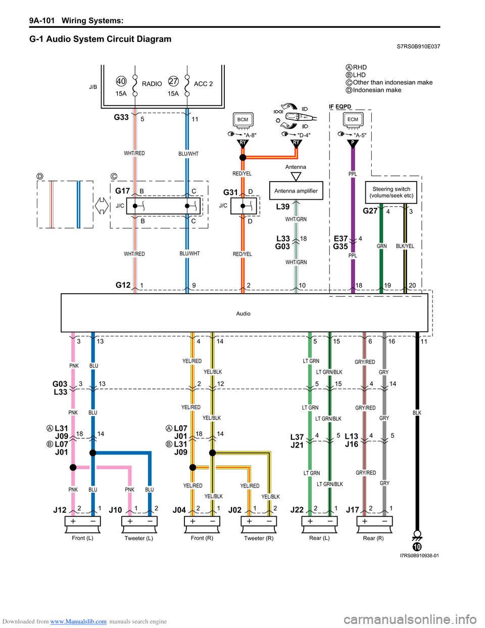
G-1 Audio System Circuit DiagramS7RS0B910E037
PPL
PPL
G335
GRY
18141814L37J21
G03 L333 13 2
515 14
4 5
4
5
11
21 1
2 2
1 1
2 2
1 2
1
3
13 4
14 5
15 6
16 11
RY"D-4"RY
WHT/RED
G121
J/C
G17
WHT/RED
J/B15ARADIO
40
RED/YEL
J/C
G31
BCM
"A-8"
Antenna amplifier
WHT/GRN
L39
L33
G0318E37
G354
WHT/GRN
BLU/WHT
BLU/WHT
15A ACC 2
27
BLK
10
Tweeter (L)Front (L)
PNKBLU
J12
J10
Tweeter (R)Front (R)
J04J02
YEL/BLK
YEL/RED
Rear (R)Rear (L)
LT GRN
LT GRN/BLKPNKBLUPNKBLUYEL/BLK
YEL/RED
YEL/BLK
YEL/REDLT GRN
LT GRN/BLK
GRY/RED
GRY
GRY/RED
PNKBLUYEL/BLK
YEL/REDLT GRN
LT GRN/BLKGRY
GRY/RED
12
Audio
RED/YEL
921 0
J22J17
B
B C
C D
DSteering switch
(volume/seek etc)
G27
GRN
1920
BLK/YEL
4 3
L13
J16
4
P
ECM
"A-5"
18
RHD
LHD
Other than indonesian make
Indonesian make
ABC
DC
D
Antenna
L31
J09
L07 J01A
B
L07 J01
L31 J09A
B
IF EQPD
I7RS0B910938-01
Page 1273 of 1496
Downloaded from www.Manualslib.com manuals search engine Wiring Systems: 9A-102
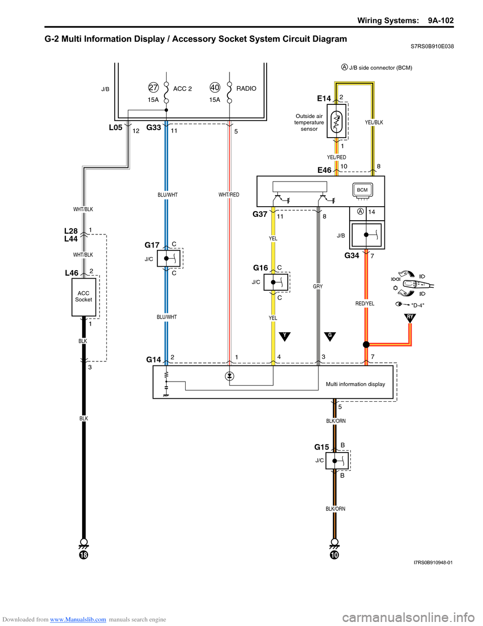
G-2 Multi Information Display / Accessory Socket System Circuit DiagramS7RS0B910E038
11
BLU/WHT
BLU/WHT
15AACC 2
27
J/C
G17
L28
L44
YG
Multi information display
J/B
BCM
J/B
G34
7
14
RED/YEL
10
BLK/ORN
2
BLK/ORN
15A RADIO
40
G335
WHT/RED
G141
3
J/C
YEL
YEL
G16
4
57
G15
J/C
12L05
WHT/BLK
L46
ACC
Socket
2
1
18
WHT/BLK
BLK
BLK
3 1
C
C
B
B
C
C
GRY
G378
11
"D-4"
RY
YEL/RED
YEL/BLK
2E14
1
8
10E46
A
J/B side connector (BCM)
A
Outside air
temperature sensor
I7RS0B910948-01
Page 1284 of 1496
Downloaded from www.Manualslib.com manuals search engine 9B-2 Lighting Systems:
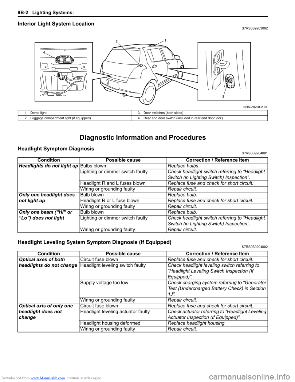
Interior Light System LocationS7RS0B9203002
Diagnostic Information and Procedures
Headlight Symptom DiagnosisS7RS0B9204001
Headlight Leveling System Symptom Diagnosis (If Equipped)S7RS0B9204002
13
2
4
I4RS0A920002-01
1. Dome light 3. Door switches (both sides)
2. Luggage compartment light (if equipped) 4. Rear end door switch (included in rear end door lock)
ConditionPossible cause Correction / Reference Item
Headlights do not light up Bulbs blown Replace bulbs.
Lighting or dimmer switch faulty Check headlight switch referring to “Headlight
Switch (in Lighting Switch) Inspection”.
Headlight R and L fuses blown Replace fuse and check for short circuit.
Wiring or grounding faulty Repair circuit.
Only one headlight does
not light up Bulb blown
Replace bulb.
Headlight R or L fuse blown Replace fuse and check for short circuit.
Wiring or grounding faulty Repair circuit.
Only one beam (“Hi” or
“Lo”) does not light Bulb blown
Replace bulb.
Lighting or dimmer switch faulty Check headlight switch referring to “Headlight
Switch (in Lighting Switch) Inspection”.
Wiring or grounding faulty Repair circuit.
ConditionPossible cause Correction / Reference Item
Optical axes of both
headlights do not change Circuit fuse blown
Replace fuse and check for short circuit.
Headlight leveling switch faulty Check headlight leveling switch referring to
“Headlight Leveling Switch Inspection (If
Equipped)”.
Supply voltage too low Check charging system referring to “Generator
Test (Undercharged Battery Check) in Section
1J”.
Wiring or grounding faulty Repair circuit.
Optical axis of only one
headlight does not
change Circuit fuse blown
Replace fuse and check for short circuit.
Headlight leveling actuator faulty Check actuator referring to “Headlight Leveling
Actuator Inspection (If Equipped)”.
Headlight housing deformed Replace headlight housing.
Wiring or grounding faulty Repair circuit.
Page 1285 of 1496
Downloaded from www.Manualslib.com manuals search engine Lighting Systems: 9B-3
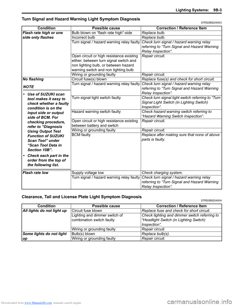
Turn Signal and Hazard Warning Light Symptom DiagnosisS7RS0B9204003
Clearance, Tail and License Plate Light Symptom DiagnosisS7RS0B9204004
ConditionPossible cause Correction / Reference Item
Flash rate high or one
side only flashes Bulb blown on “flash rate high”-side
Replace bulb.
Incorrect bulb Replace bulb.
Turn signal / hazard warning relay faulty Check turn signal / hazard warning relay
referring to “Turn Signal and Hazard Warning
Relay Inspection”.
Open circuit or high resistance existing
either; between turn signal switch and
non lighting bulb, or between hazard
warning switch and non lighting bulb Repair circuit.
Wiring or grounding faulty Repair circuit.
No flashing
NOTE
• Use of SUZUKI scan tool makes it easy to
check whether a faulty
condition is on the
input side or output
side of BCM. For
checking procedure,
refer to “Diagnosis
Using Output Test
Function of SUZUKI
Scan Tool” under
“Scan Tool Data in
Section 10B”.
• Check each part in the order from the top of
the following list.
Circuit fuse(s) blown Replace fuse(s) and check for short circuit.
Turn signal / hazard warning relay faulty Check turn signal / hazard warning relay
referring to “Turn Signal and Hazard Warning
Relay Inspection”.
Turn signal light switch faulty Check turn signal light switch referring to “Turn
Signal Light Switch (in Lighting Switch)
Inspection”.
Hazard warning switch faulty Check hazard warning switch referring to
“Hazard Warning Switch Inspection”.
Open circuit or high resistance existing
between battery and switch Repair circuit.
Wiring or grounding faulty Repair circuit.
BCM faulty Replace after making sure that none of above
parts is faulty.
Flash rate low Supply voltage low Check charging system.
Turn signal / hazard warning relay faulty Check turn signal / hazard warning relay
referring to “Turn Signal and Hazard Warning
Relay Inspection”.
ConditionPossible cause Correction / Reference Item
All lights do not light up Circuit fuse blown Replace fuse and check for short circuit.
Lighting and dimmer switch of
combination switch faulty Check lighting and dimmer switch referring to
“Headlight Switch (in Lighting Switch)
Inspection”.
Wiring or grounding faulty Repair circuit.
Some lights do not light
up Bulb(s) blown
Replace bulb(s).
Wiring or grounding faulty Repair circuit.
Page 1286 of 1496
Downloaded from www.Manualslib.com manuals search engine 9B-4 Lighting Systems:
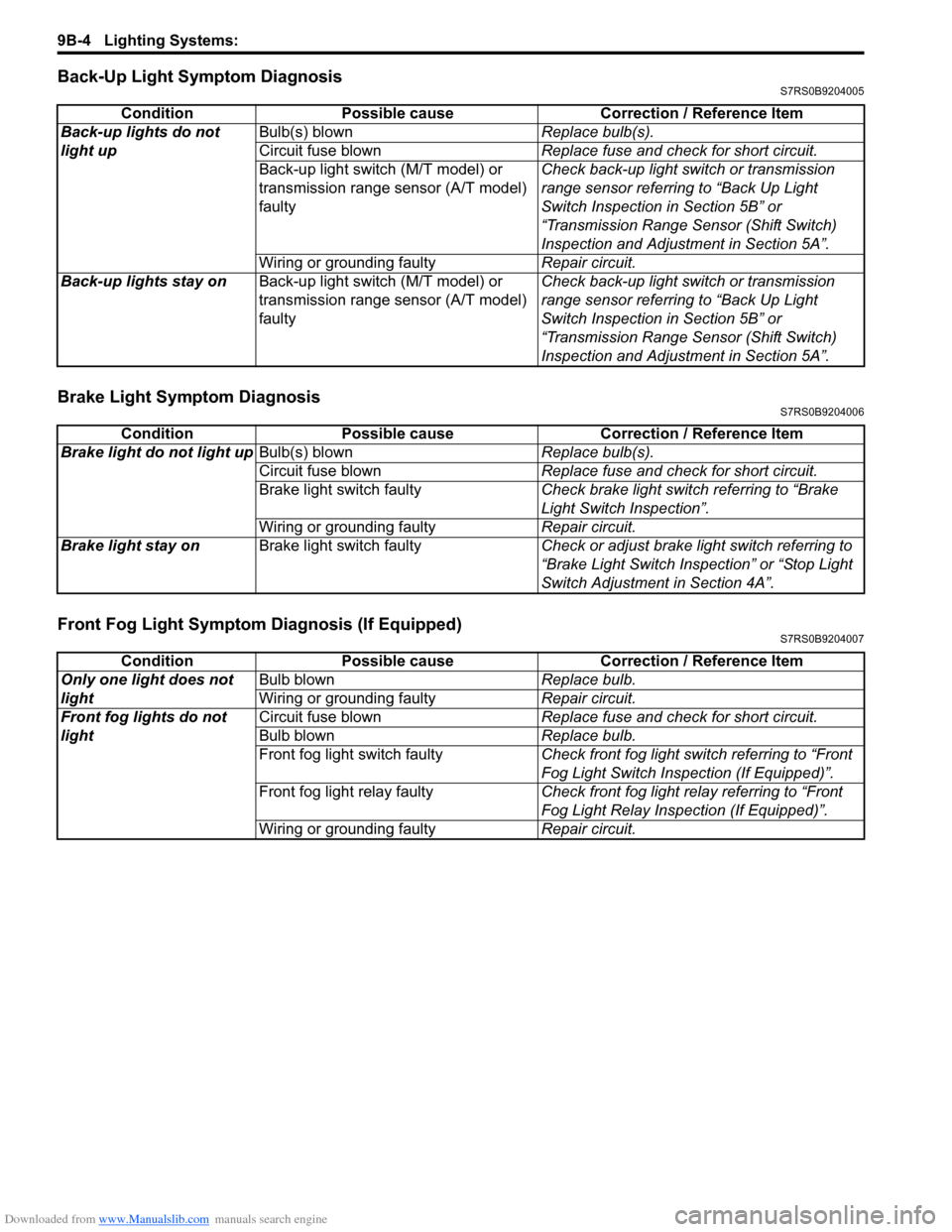
Back-Up Light Symptom DiagnosisS7RS0B9204005
Brake Light Symptom DiagnosisS7RS0B9204006
Front Fog Light Symptom Diagnosis (If Equipped)S7RS0B9204007
ConditionPossible cause Correction / Reference Item
Back-up lights do not
light up Bulb(s) blown
Replace bulb(s).
Circuit fuse blown Replace fuse and check for short circuit.
Back-up light switch (M/T model) or
transmission range sensor (A/T model)
faulty Check back-up light switch or transmission
range sensor referring to “Back Up Light
Switch Inspection in Section 5B” or
“Transmission Range Sensor (Shift Switch)
Inspection and Adjustment in Section 5A”.
Wiring or grounding faulty Repair circuit.
Back-up lights stay on Back-up light switch (M/T model) or
transmission range sensor (A/T model)
faulty Check back-up light switch or transmission
range sensor referring to “Back Up Light
Switch Inspection in Section 5B” or
“Transmission Range Sensor (Shift Switch)
Inspection and Adjustment in Section 5A”.
Condition
Possible cause Correction / Reference Item
Brake light do not light up Bulb(s) blown Replace bulb(s).
Circuit fuse blown Replace fuse and check for short circuit.
Brake light switch faulty Check brake light switch referring to “Brake
Light Switch Inspection”.
Wiring or grounding faulty Repair circuit.
Brake light stay on Brake light switch faulty Check or adjust brake light switch referring to
“Brake Light Switch Inspection” or “Stop Light
Switch Adjustment in Section 4A”.
ConditionPossible cause Correction / Reference Item
Only one light does not
light Bulb blown
Replace bulb.
Wiring or grounding faulty Repair circuit.
Front fog lights do not
light Circuit fuse blown
Replace fuse and check for short circuit.
Bulb blown Replace bulb.
Front fog light switch faulty Check front fog light switch referring to “Front
Fog Light Switch Inspection (If Equipped)”.
Front fog light relay faulty Check front fog light relay referring to “Front
Fog Light Relay Inspection (If Equipped)”.
Wiring or grounding faulty Repair circuit.
Page 1287 of 1496
Downloaded from www.Manualslib.com manuals search engine Lighting Systems: 9B-5
Interior Light Symptom DiagnosisS7RS0B9204008
NOTE
• Use of SUZUKI scan tool makes it easy to check whether a faulty condition is on the input side or
output side of BCM. For checking procedure, re fer to “Diagnosis Using Output Test Function of
SUZUKI Scan Tool” under “Scan Tool Data in Section 10B”.
• Check each part in the order from the top of the following list.
Repair Instructions
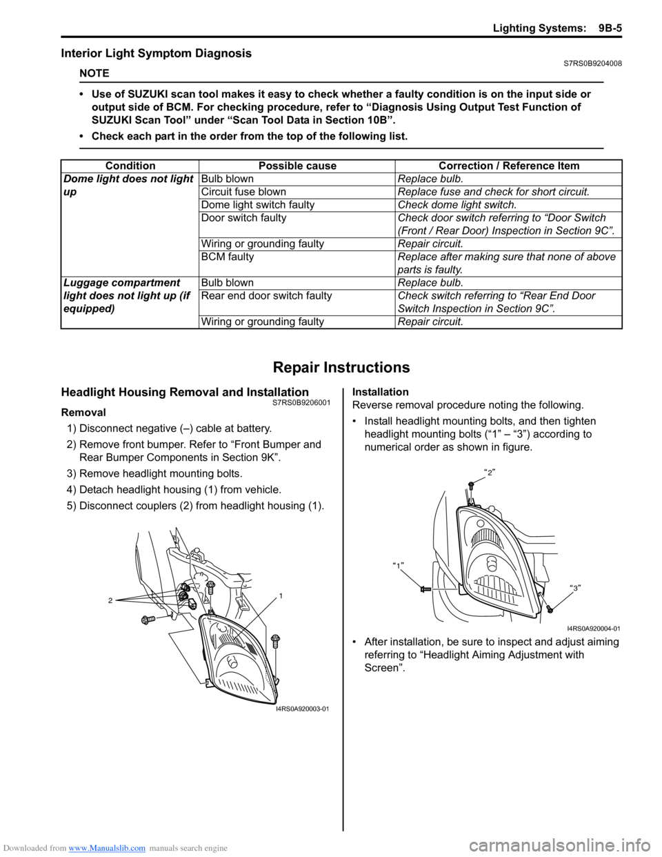
Headlight Housing Removal and InstallationS7RS0B9206001
Removal 1) Disconnect negative (–) cable at battery.
2) Remove front bumper. Refer to “Front Bumper and Rear Bumper Componen ts in Section 9K”.
3) Remove headlight mounting bolts.
4) Detach headlight housing (1) from vehicle.
5) Disconnect couplers (2) from headlight housing (1). Installation
Reverse removal procedure noting the following.
• Install headlight mounting bolts, and then tighten
headlight mounting bolts (“1” – “3”) according to
numerical order as shown in figure.
• After installation, be sure to inspect and adjust aiming referring to “Headlight Aiming Adjustment with
Screen”.
Condition Possible cause Correction / Reference Item
Dome light does not light
up Bulb blown
Replace bulb.
Circuit fuse blown Replace fuse and check for short circuit.
Dome light switch faulty Check dome light switch.
Door switch faulty Check door switch referring to “Door Switch
(Front / Rear Door) Inspection in Section 9C”.
Wiring or grounding faulty Repair circuit.
BCM faulty Replace after making sure that none of above
parts is faulty.
Luggage compartment
light does not light up (if
equipped) Bulb blown
Replace bulb.
Rear end door switch faulty Check switch referring to “Rear End Door
Switch Inspection in Section 9C”.
Wiring or grounding faulty Repair circuit.
2 1
I4RS0A920003-01
2
1 3
I4RS0A920004-01
Page 1292 of 1496
Downloaded from www.Manualslib.com manuals search engine 9B-10 Lighting Systems:
Turn Signal and Hazard Warning Relay
Inspection
S7RS0B9206012
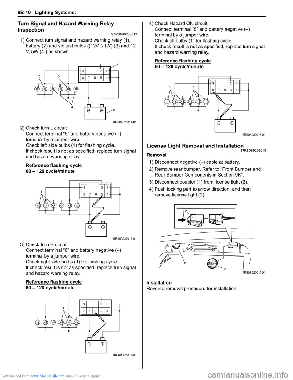
1) Connect turn signal and hazard warning relay (1), battery (2) and six test bulbs ((12V, 21W) (3) and 12
V, 5W (4)) as shown.
2) Check turn L circuit Connect terminal “5” and battery negative (–)
terminal by a jumper wire.
Check left side bulbs (1) for flashing cycle.
If check result is not as specified, replace turn signal
and hazard warning relay.
Reference flashing cycle
60 – 120 cycle/minute
3) Check turn R circuit Connect terminal “6” and battery negative (–)
terminal by a jumper wire.
Check right side bulbs (1) for flashing cycle.
If check result is not as specified, replace turn signal
and hazard warning relay.
Reference flashing cycle
60 – 120 cycle/minute 4) Check Hazard ON circuit
Connect terminal “8” and battery negative (–)
terminal by a jumper wire.
Check all bulbs (1) for flashing cycle.
If check result is not as sp ecified, replace turn signal
and hazard warning relay.
Reference flashing cycle
60 – 120 cycle/minute
License Light Removal and InstallationS7RS0B9206013
Removal
1) Disconnect negative (–) cable at battery.
2) Remove rear bumper. Refe r to “Front Bumper and
Rear Bumper Components in Section 9K”.
3) Disconnect coupler (1) from license light (2).
4) Push locking part to arrow direction, and then remove license light (2).
Installation
Reverse removal procedure for installation.
2
4
33
3
87
12
654
1
I4RS0A920014-01
13
87
12
654
I4RS0A920015-01
3
87
12
6541
I4RS0A920016-01
3
87
12
6
5411
I4RS0A920017-01
2
2
1
2
I4RS0B920010-01
Page 1299 of 1496
Downloaded from www.Manualslib.com manuals search engine Instrumentation / Driver Info. / Horn: 9C-4
Schematic and Routing Diagram
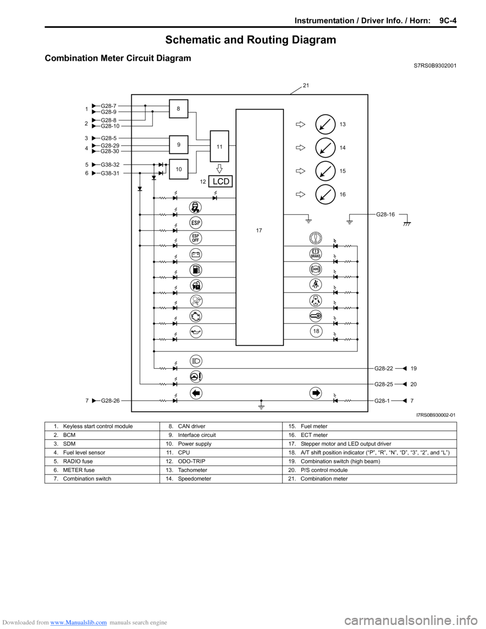
Combination Meter Circuit DiagramS7RS0B9302001
16
15
14
13
G28-5
5
6
3
G28-26
7
G28-2219
G28-2520
G28-17
12
10 11
21
9
17
G28-304G28-29
18
G28-16
G28-9
G28-10G28-8 G28-7
1
2 8
G38-31
G38-32
I7RS0B930002-01
1. Keyless start control module
8. CAN driver 15. Fuel meter
2. BCM 9. Interface circuit 16. ECT meter
3. SDM 10. Power supply 17. Stepper motor and LED output driver
4. Fuel level sensor 11. CPU 18. A/T shift position indicator (“P”, “R”, “N”, “D”, “3”, “2”, and “L”)
5. RADIO fuse 12. ODO-TRIP 19. Combination switch (high beam)
6. METER fuse 13. Tachometer 20. P/S control module
7. Combination switch 14. Speedometer 21. Combination meter