2007 SUZUKI SWIFT Clé
[x] Cancel search: CléPage 747 of 1496
Downloaded from www.Manualslib.com manuals search engine Automatic Transmission/Transaxle: 5A-103
Installation
Reverse removal procedure noting the following.
• Connect TCM connectors securely.
• If the vehicle is equipped with air bag system, be sure to enable air bag system after TCM is back in place.
Refer to “Enabling Air Bag System in Section 8B”.
A/T Relay InspectionS7RS0B5106027
1) Disconnect negative cable at battery.
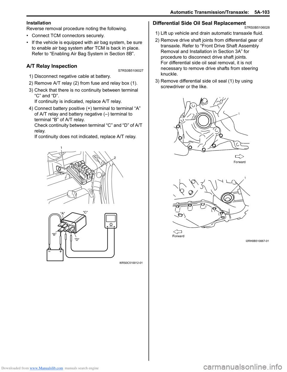
2) Remove A/T relay (2) from fuse and relay box (1).
3) Check that there is no continuity between terminal “C” and “D”.
If continuity is indicated, replace A/T relay.
4) Connect battery positive (+ ) terminal to terminal “A”
of A/T relay and battery negative (–) terminal to
terminal “B” of A/T relay.
Check continuity between terminal “C” and “D” of A/T
relay.
If continuity does not indicated, replace A/T relay.
Differential Side Oil Seal ReplacementS7RS0B5106028
1) Lift up vehicle and drain automatic transaxle fluid.
2) Remove drive shaft joints from differential gear of transaxle. Refer to “Front Drive Shaft Assembly
Removal and Installation in Section 3A” for
procedure to disconnect drive shaft joints.
For differential side oil seal removal, it is not
necessary to remove drive shafts from steering
knuckle.
3) Remove differential side oil seal (1) by using screwdriver or the like.
"D"
"B" "A"
"C"
1
2
I6RS0C510012-01
I2RH0B510067-01
Page 751 of 1496
Downloaded from www.Manualslib.com manuals search engine Automatic Transmission/Transaxle: 5A-107
Remounting1) Make sure that torque converter is installed correctly to transaxle.
Refer to “Automatic Transaxle Unit Assembly”.
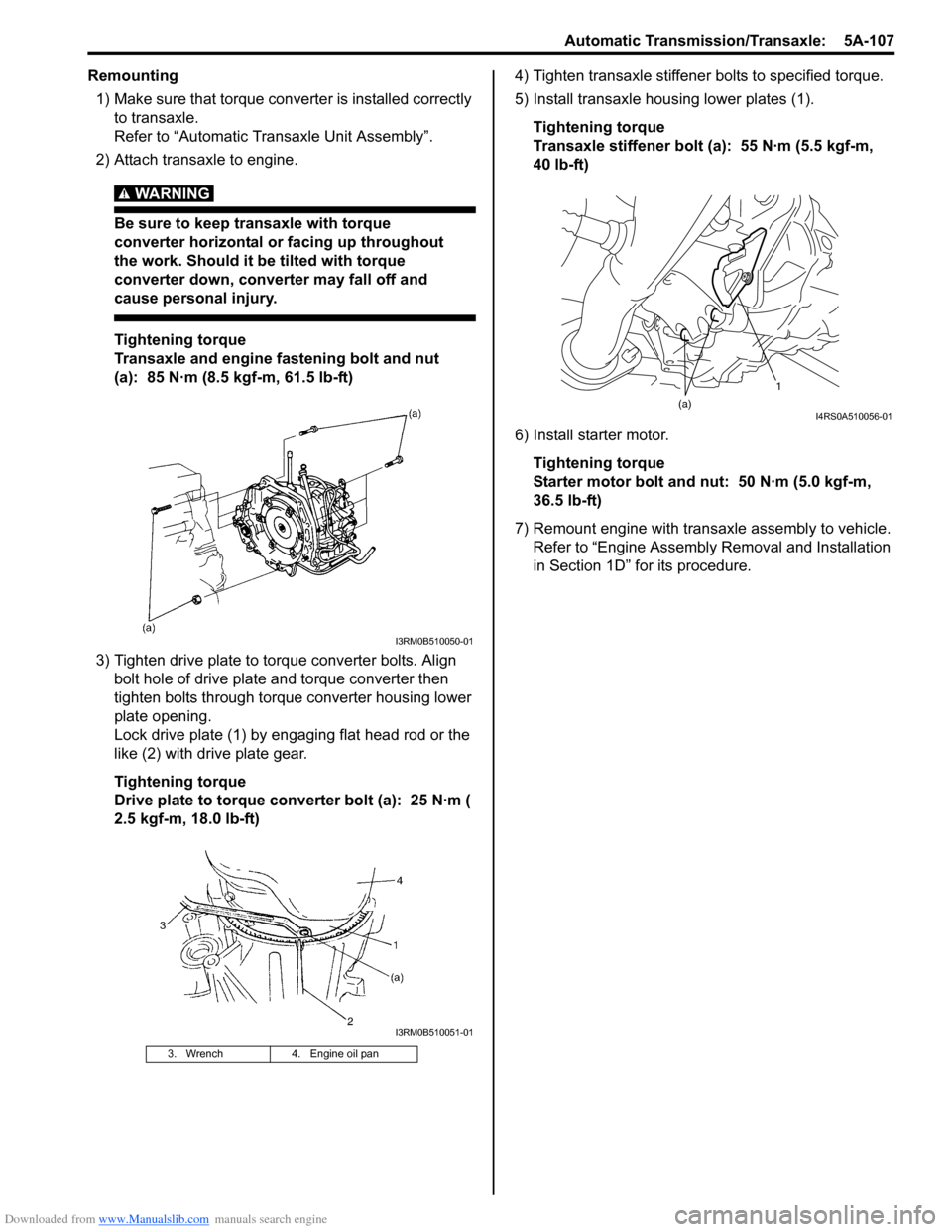
2) Attach transaxle to engine.
WARNING!
Be sure to keep transaxle with torque
converter horizontal or facing up throughout
the work. Should it be tilted with torque
converter down, converter may fall off and
cause personal injury.
Tightening torque
Transaxle and engine fastening bolt and nut
(a): 85 N·m (8.5 kgf-m, 61.5 lb-ft)
3) Tighten drive plate to torque converter bolts. Align bolt hole of drive plate and torque converter then
tighten bolts through torque converter housing lower
plate opening.
Lock drive plate (1) by engaging flat head rod or the
like (2) with drive plate gear.
Tightening torque
Drive plate to torque converter bolt (a): 25 N·m (
2.5 kgf-m, 18.0 lb-ft) 4) Tighten transaxle stiffener bolts to specified torque.
5) Install transaxle housing lower plates (1).
Tightening torque
Transaxle stiffener bolt (a): 55 N·m (5.5 kgf-m,
40 lb-ft)
6) Install starter motor. Tightening torque
Starter motor bolt and nut: 50 N·m (5.0 kgf-m,
36.5 lb-ft)
7) Remount engine with transaxle assembly to vehicle. Refer to “Engine Assembly Removal and Installation
in Section 1D” for its procedure.
3. Wrench 4. Engine oil pan
I3RM0B510050-01
I3RM0B510051-01
1
(a)
I4RS0A510056-01
Page 754 of 1496
Downloaded from www.Manualslib.com manuals search engine 5A-110 Automatic Transmission/Transaxle:
Automatic Transaxle Unit DisassemblyS7RS0B5106033
CAUTION!
• Thoroughly clean transaxle exterior before overhauling it.
• Keep working table, tools and hands clean while overhauling.
• Use special care to handle aluminum parts so as not to damage them.
• Do not expose removed parts to dust. Keep them always clean.
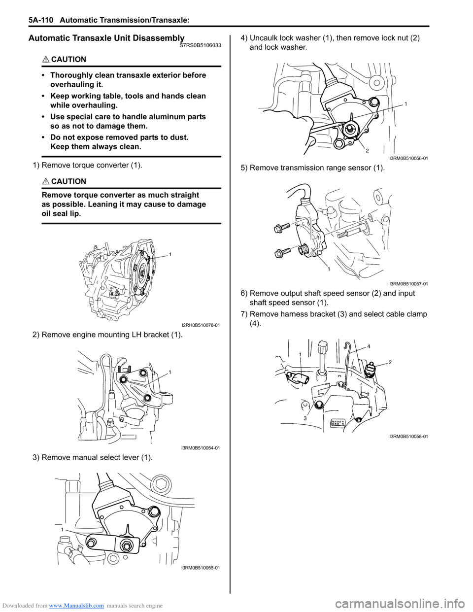
1) Remove torque converter (1).
CAUTION!
Remove torque converte r as much straight
as possible. Leaning it may cause to damage
oil seal lip.
2) Remove engine mounting LH bracket (1).
3) Remove manual select lever (1). 4) Uncaulk lock washer (1),
then remove lock nut (2)
and lock washer.
5) Remove transmission range sensor (1).
6) Remove output shaft speed sensor (2) and input shaft speed sensor (1).
7) Remove harness bracket (3) and select cable clamp (4).
I2RH0B510078-01
I3RM0B510054-01
1
I3RM0B510055-01
1
2
I3RM0B510056-01
I3RM0B510057-01
I3RM0B510058-01
Page 766 of 1496
Downloaded from www.Manualslib.com manuals search engine 5A-122 Automatic Transmission/Transaxle:
Oil Pump Assembly Disassembly and
Reassembly
S7RS0B5106035
Disassembly1) Remove O-ring from pump body.
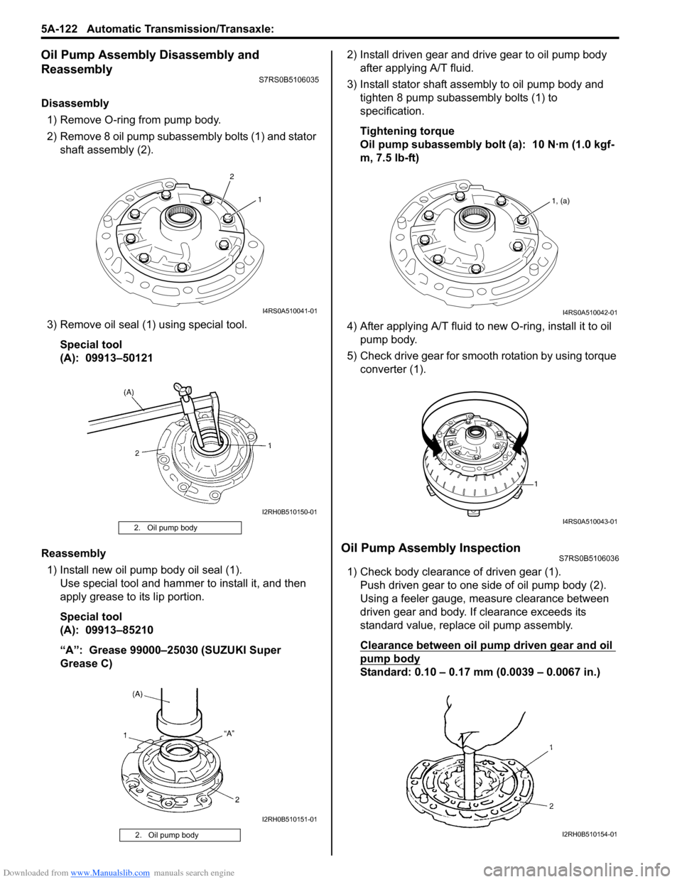
2) Remove 8 oil pump subassembly bolts (1) and stator shaft assembly (2).
3) Remove oil seal (1) using special tool. Special tool
(A): 09913–50121
Reassembly 1) Install new oil pump body oil seal (1). Use special tool and hammer to install it, and then
apply grease to its lip portion.
Special tool
(A): 09913–85210
“A”: Grease 99000–25030 (SUZUKI Super
Grease C) 2) Install driven gear and drive gear to oil pump body
after applying A/T fluid.
3) Install stator shaft assembly to oil pump body and tighten 8 pump subassembly bolts (1) to
specification.
Tightening torque
Oil pump subassembly bolt (a): 10 N·m (1.0 kgf-
m, 7.5 lb-ft)
4) After applying A/T fluid to new O-ring, install it to oil pump body.
5) Check drive gear for smooth rotation by using torque converter (1).
Oil Pump Assembly InspectionS7RS0B5106036
1) Check body clearance of driven gear (1).Push driven gear to one side of oil pump body (2).
Using a feeler gauge, m easure clearance between
driven gear and body. If clearance exceeds its
standard value, replace oil pump assembly.
Clearance between oil pump driven gear and oil
pump body
Standard: 0.10 – 0.17 mm (0.0039 – 0.0067 in.)
2. Oil pump body
2. Oil pump body
2 1
I4RS0A510041-01
I2RH0B510150-01
I2RH0B510151-01
1, (a)
I4RS0A510042-01
1
I4RS0A510043-01
I2RH0B510154-01
Page 767 of 1496

Downloaded from www.Manualslib.com manuals search engine Automatic Transmission/Transaxle: 5A-123
2) Check tip clearance of both drive and driven gears.Using a feeler gauge, m easure clearance between
drive and driven gear tips. If clearance exceeds its
standard value, replace oil pump assembly.
Tip clearance between oil pump drive gear and
oil pump driven gear
Standard: 0.07 – 0.15 mm (0.0028 – 0.0059 in.)
3) Check side clearance of both gears. Using a straightedge (1) and a feeler gauge (2),
measure side clearance between gears and pump
body.
If clearance exceeds its standard value, replace oil
pump assembly.
Side clearance between gears and oil pump body
Standard: 0.02 – 0.05 mm (0.0008 – 0.0019 in.)
4) Using special tool, measure stator shaft bush (1) bore.
If measured stator shaft bush bore is out of
specifications, replace oil pump assembly with new
one.
Special tool
(A): 09900–20605
Stator shaft bush bore
Standard: 18.424 – 18.450 mm (0.7254 – 0.7264
in.) 5) Install direct clutch asse
mbly (1) to stator shaft
assembly (2), then ensure that direct clutch
assembly turns smoothly.
If unsmooth rotation or noise are found in oil pump
assembly, replace oil pump assembly with new one.
This check should also be done to input shaft
assembly and replace input shaft assembly if
necessary.
6) Using special tool, measure oil pump body bush bore.
If measured oil pump body bush (1) bore is out of
specifications, replace o il pump assembly with new
one. Torque converter also needs to be checked.
Replace torque converter, if necessary.
Special tool
(A): 09900–20605
Oil pump body bush bore
Standard: 38.113 – 38.138 mm (1.5005 – 1.5015
in.)
I2RH0B510155-01
I2RH0B510156-01
I2RH0B510157-01
I2RH0B510158-01
I2RH0B510159-01
Page 791 of 1496

Downloaded from www.Manualslib.com manuals search engine Automatic Transmission/Transaxle: 5A-147
3) Install new differential side oil seal to transaxle case by using special tools.
Special tool
(A): 09924–74510
(B): 09944–88220
Differential side oil seal installing depth
“a”: 3.8 – 4.8 mm (0.15 – 0.19 in.)
4) Apply grease to oil seal lip. : Grease 99000–25030 (SUZUKI Super Grease C)
Automatic Transaxle Unit Inspection and
Adjustment
S7RS0B5106059
Inspection
Brake discs
Dry and inspect them for pitting, burn flaking, significant
wear, glazing, cracking, charring and chips or metal
particles imbedded in lining.
If discs show any of the ab ove conditions, replacement
is required.
NOTE
• If disc lining is exfoliated or discolored, replace all discs.
• Before assembling new discs, soak them in A/T fluid for at least two hours.
Brake separator plates and retaining plates
Dry plates and check for discol oration. If plate surface is
smooth and even color smear is indicated, plate should
be reused. If severe heat spot discoloration or surface
scuffing is indicated, plate must be replaced.
Brake return spring subassembly
Measure free length of each brake return spring
subassembly.
Evidence of extreme heat or burning in the area of clutch
may have caused springs to take heat set and would
require their replacement.
Free length of 1st & reverse brake return spring
subassembly
“a”: 21.71 mm (0.855 in.)
Free length of 2nd brake return spring subassembly
“a”: 15.85 mm (0.624 in.)
NOTE
• Do not apply excessive force when measuring spring free length.
• Perform measurement at several points.
I2RH0B510252-01
I2RH01510147-01
I2RH0B510253-01
I2RH0B510173-01
Page 794 of 1496
Downloaded from www.Manualslib.com manuals search engine 5A-150 Automatic Transmission/Transaxle:
Automatic Transaxle Unit AssemblyS7RS0B5106060
CAUTION!
• Automatic transaxle consists of highly precise parts. As even flaw in small part
may cause oil leakage or decrease in
function, check each part carefully before
installation.
• Clean all parts with compressed air. Never use wiping cloths or rags.
• Before assembling new clutch or brake discs, soak them in automatic transaxle
fluid for at least 2 hours.
• Be sure to use new gaskets and O-rings.
• Lubricate O-rings with automatic transaxle
fluid.
• Apply automatic transaxle fluid on sliding or rotating surfaces of the parts before
assembly.
• Use Suzuki Super Grease “C” to retain parts in place.
• Be sure to install thrust bearings and races in correct direction and position.
• Make sure that snap ring ends are not aligned with one of cut outs and are
installed in groove correctly.
• Do not use adhesive cements on gaskets and similar parts.
• Be sure to torque each bolt and nut to specification.
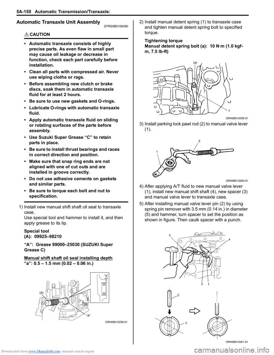
1) Install new manual shift sh aft oil seal to transaxle
case.
Use special tool and hammer to install it, and then
apply grease to its lip.
Special tool
(A): 09925–98210
“A”: Grease 99000–25030 (SUZUKI Super
Grease C)
Manual shift shaft oil seal installing depth
“a”: 0.5 – 1.5 mm (0.02 – 0.06 in.) 2) Install manual detent spring (1) to transaxle case
and tighten manual detent spring bolt to specified
torque.
Tightening torque
Manual detent spring bolt (a): 10 N·m (1.0 kgf-
m, 7.5 lb-ft)
3) Install parking lock pawl ro d (2) to manual valve lever
(1).
4) After applying A/T fluid to new manual valve lever (1), install new manual shift shaft (4), new spacer (3)
and manual valve lever to transaxle case.
5) After installing manual valve lever pin (2) by using spring pin remover with 3.5 mm (0.14 in.) in diameter
(5) and hammer, turn spacer to set the position as
shown in figure. Then caulk spacer with a punch.
“a”
(A)
“A”
I2RH0B510258-01
I2RH0B510259-01
I2RH0B510260-01
I2RH0B510261-01
Page 805 of 1496
Downloaded from www.Manualslib.com manuals search engine Automatic Transmission/Transaxle: 5A-161
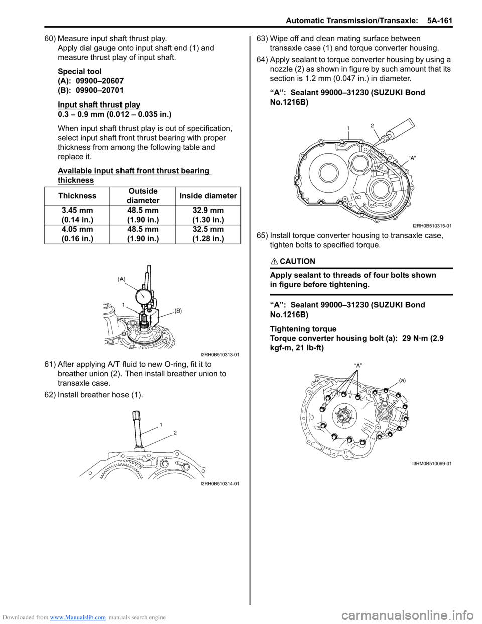
60) Measure input shaft thrust play.Apply dial gauge onto input shaft end (1) and
measure thrust play of input shaft.
Special tool
(A): 09900–20607
(B): 09900–20701
Input shaft thrust play
0.3 – 0.9 mm (0.012 – 0.035 in.)
When input shaft thrust play is out of specification,
select input shaft front th rust bearing with proper
thickness from among the following table and
replace it.
Available input shaft front thrust bearing
thickness
61) After applying A/T fluid to new O-ring, fit it to breather union (2). Then install breather union to
transaxle case.
62) Install breather hose (1). 63) Wipe off and clean mating surface between
transaxle case (1) and torque converter housing.
64) Apply sealant to torque converter housing by using a nozzle (2) as shown in figure by such amount that its
section is 1.2 mm (0.047 in.) in diameter.
“A”: Sealant 99000–31230 (SUZUKI Bond
No.1216B)
65) Install torque converter housing to transaxle case, tighten bolts to specified torque.
CAUTION!
Apply sealant to threads of four bolts shown
in figure before tightening.
“A”: Sealant 99000–31230 (SUZUKI Bond
No.1216B)
Tightening torque
Torque converter housing bolt (a): 29 N·m (2.9
kgf-m, 21 lb-ft)
Thickness
Outside
diameter Inside diameter
3.45 mm
(0.14 in.) 48.5 mm
(1.90 in.) 32.9 mm
(1.30 in.)
4.05 mm
(0.16 in.) 48.5 mm
(1.90 in.) 32.5 mm
(1.28 in.)
I2RH0B510313-01
I2RH0B510314-01
1 2
“A”
I2RH0B510315-01
I3RM0B510069-01