2007 SUZUKI SWIFT 0b -10
[x] Cancel search: 0b -10Page 443 of 1496
Downloaded from www.Manualslib.com manuals search engine Front Suspension: 2B-10
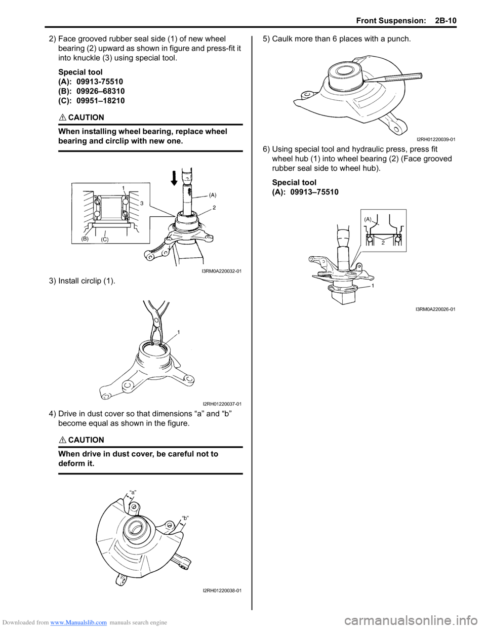
2) Face grooved rubber seal side (1) of new wheel bearing (2) upward as shown in figure and press-fit it
into knuckle (3) using special tool.
Special tool
(A): 09913-75510
(B): 09926–68310
(C): 09951–18210
CAUTION!
When installing wheel bearing, replace wheel
bearing and circlip with new one.
3) Install circlip (1).
4) Drive in dust cover so that dimensions “a” and “b” become equal as shown in the figure.
CAUTION!
When drive in dust cover, be careful not to
deform it.
5) Caulk more than 6 places with a punch.
6) Using special tool and hydraulic press, press fit
wheel hub (1) into wheel bearing (2) (Face grooved
rubber seal side to wheel hub).
Special tool
(A): 09913–75510
I3RM0A220032-01
I2RH01220037-01
I2RH01220038-01
I2RH01220039-01
I3RM0A220026-01
Page 464 of 1496
Downloaded from www.Manualslib.com manuals search engine 2C-10 Rear Suspension:
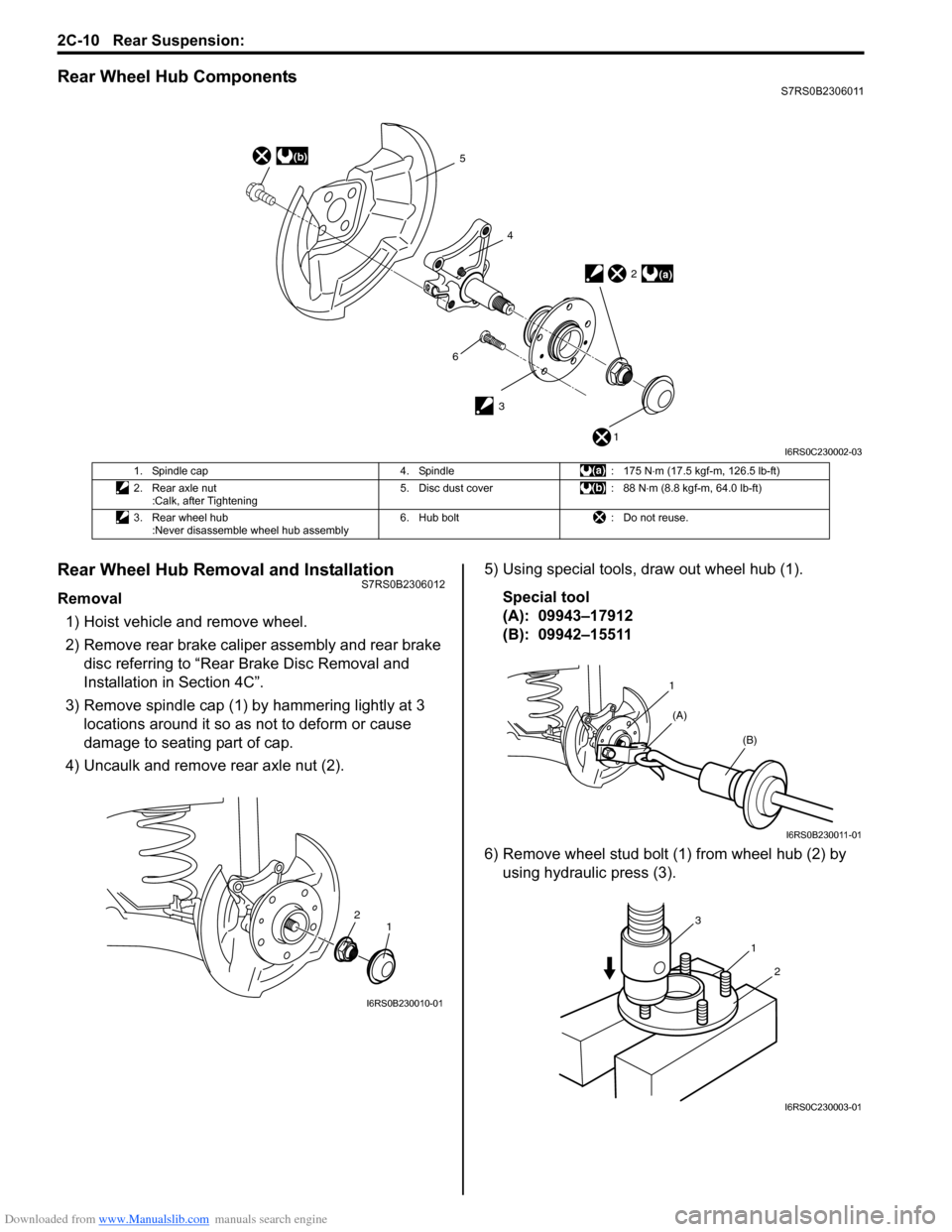
Rear Wheel Hub ComponentsS7RS0B2306011
Rear Wheel Hub Removal and InstallationS7RS0B2306012
Removal1) Hoist vehicle and remove wheel.
2) Remove rear brake caliper assembly and rear brake disc referring to “Rear Brake Disc Removal and
Installation in Section 4C”.
3) Remove spindle cap (1) by hammering lightly at 3 locations around it so as not to deform or cause
damage to seating part of cap.
4) Uncaulk and remove rear axle nut (2). 5) Using special tools, draw out wheel hub (1).
Special tool
(A): 09943–17912
(B): 09942–15511
6) Remove wheel stud bolt (1) from wheel hub (2) by using hydraulic press (3).
(b)5
4
3
(a)2
1
6
I6RS0C230002-03
1. Spindle cap 4. Spindle: 175 N⋅m (17.5 kgf-m, 126.5 lb-ft)
2. Rear axle nut :Calk, after Tightening 5. Disc dust cover
: 88 N⋅m (8.8 kgf-m, 64.0 lb-ft)
3. Rear wheel hub :Never disassemble wheel hub assembly 6. Hub bolt
: Do not reuse.
2
1
I6RS0B230010-01
1
(A) (B)
I6RS0B230011-01
1
3
2
I6RS0C230003-01
Page 488 of 1496
Downloaded from www.Manualslib.com manuals search engine 3A-10 Drive Shaft / Axle:
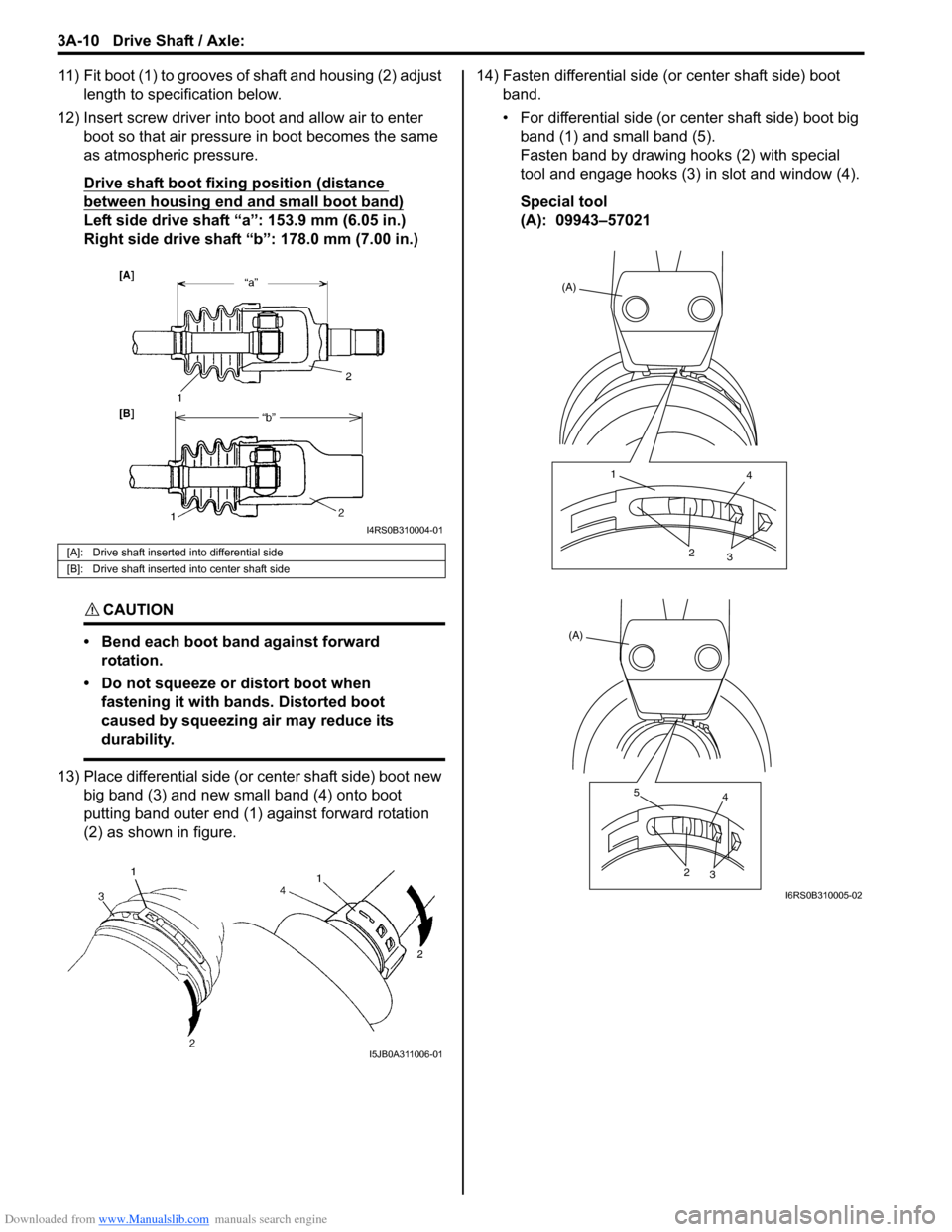
11) Fit boot (1) to grooves of shaft and housing (2) adjust
length to specification below.
12) Insert screw driver into boot and allow air to enter boot so that air pressure in boot becomes the same
as atmospheric pressure.
Drive shaft boot fixing position (distance
between housing end and small boot band)
Left side drive shaft “a”: 153.9 mm (6.05 in.)
Right side drive shaft “b”: 178.0 mm (7.00 in.)
CAUTION!
• Bend each boot band against forward rotation.
• Do not squeeze or distort boot when fastening it with bands. Distorted boot
caused by squeezing air may reduce its
durability.
13) Place differential side (or center shaft side) boot new big band (3) and new small band (4) onto boot
putting band outer end (1) against forward rotation
(2) as shown in figure. 14) Fasten differential side (or center shaft side) boot
band.
• For differential side (or center shaft side) boot big band (1) and small band (5).
Fasten band by drawing hooks (2) with special
tool and engage hooks (3) in slot and window (4).
Special tool
(A): 09943–57021
[A]: Drive shaft inserted into differential side
[B]: Drive shaft inserted into center shaft side
I4RS0B310004-01
I5JB0A311006-01
(A)
1 4
2 3
(A)
5 4
2 3
I6RS0B310005-02
Page 495 of 1496

Downloaded from www.Manualslib.com manuals search engine Table of Contents 4- i
4
Section 4
CONTENTS
Brakes
Precautions ................................................. 4-1
Precautions............................................................. 4-1
Precautions for Brakes .......................................... 4-1
Brake Control System and Diagnosis ... 4A-1
Precautions........................................................... 4A-1Precautions on Brake .......................................... 4A-1
General Description ............................................. 4A-1 Brakes Construction ............................................ 4A-1
Brake Pedal Foot Protection System Construction ...................................................... 4A-2
Front Brake Hose / Pipe Co nstruction................. 4A-3
Rear Brake Hose / Pipe Construction ................. 4A-4
Diagnostic Information and Procedures ............ 4A-4 Brakes Diagnosis Note ....................................... 4A-4
Brakes Symptom Diagnosis ................................ 4A-5
Repair Instructions .............................................. 4A-7 Brake Pedal Components ................................... 4A-7
Brake Pedal Free Height Inspection ................... 4A-7
Brake Pedal Play Inspection ............................... 4A-7
Excessive Pedal Travel Inspection ..................... 4A-8
Brake Fluid Level Inspection ............................... 4A-8
Stop Light Switch Adjustment ............................. 4A-8
Air Bleeding of Brake System ............................. 4A-9
Front Brake Hose / Pipe Removal and Installation ....................................................... 4A-10
Rear Brake Hose / Pipe Removal and Installation ....................................................... 4A-10
Brake Hose and Pipe Inspection ....................... 4A-11
Master Cylinder Components............................ 4A-11
Master Cylinder Assembly Removal and Installation ....................................................... 4A-12
Master Cylinder Rese rvoir Removal and
Installation ....................................................... 4A-13
Master Cylinder Assemb ly Disassembly and
Assembly ........................................................ 4A-14
Master Cylinder Assembly Inspection ............... 4A-15
Brake Booster Components .............................. 4A-15
Booster Operation Inspection ........................... 4A-16
Brake Booster Removal and Installation ........... 4A-17
Brake Booster Inspection and Adjustment ........ 4A-18
Specifications ..................................................... 4A-18
Tightening Torque Specifications ...................... 4A-18
Special Tools and Equipmen t ........................... 4A-18 Recommended Service Material ....................... 4A-18
Front Brakes .......
..................................... 4B-1
Repair Instructions ........... ...................................4B-1
Front Disc Brake Components ............................ 4B-1
Front Disc Brake Pad On-Vehicle Inspection ...... 4B-2
Front Disc Brake Pad Removal and Installation ......................................................... 4B-2
Front Disc Brake Pad Inspection......................... 4B-3
Front Disc Brake Ca liper Removal and
Installation ......................................................... 4B-3
Front Disc Brake Caliper Disassembly and Assembly........................................................... 4B-4
Front Disc Brake Caliper In spection.................... 4B-6
Front Brake Disc Removal and Installation ......... 4B-6
Front Brake Disc Inspection ................................ 4B-7
Specifications .................... ...................................4B-8
Tightening Torque Specifications ........................ 4B-8
Special Tools and Equipmen t .............................4B-8
Recommended Service Material ......................... 4B-8
Special Tool ........................................................ 4B-8
Rear Brakes................... ........................... 4C-1
Repair Instructions ........... ...................................4C-1
Rear Disc Brake Components.............................4C-1
Rear Disc Brake Pad Removal and Installation .........................................................4C-2
Rear Disc Brake Caliper Removal and Installation .........................................................4C-3
Rear Disc Brake Pad Inspection .........................4C-6
Rear Disc Brake Caliper Disassembly and Assembly...........................................................4C-6
Rear Disc Brake Caliper Inspection ....................4C-8
Rear Flexible Hose Remova l and Installation .....4C-8
Rear Brake Disc Removal and Installation..........4C-9
Rear Brake Disc Inspection.................................4C-9
Specifications .................... .................................4C-10
Tightening Torque Specifications ......................4C-10
Special Tools and Equipmen t ...........................4C-11
Recommended Service Material .......................4C-11
Special Tool ......................................................4C-11
Parking Brake ................. ......................... 4D-1
General Description .............................................4D-1
Parking Brake Cable Construction ......................4D-1
Page 496 of 1496

Downloaded from www.Manualslib.com manuals search engine 4-ii Table of Contents
Repair Instructions ..............................................4D-2Parking Brake Inspection and Adjustment ..........4D-2
Parking Brake Cable Removal and Installation ......................................................... 4D-3
Parking Brake Lever Removal and Installation ....4D-3
Specifications .... ...................................................4D-4
Tightening Torque Specifications ........................4D-4
ABS ........................................... .................4E-1
Precautions........................................................... 4E-1
Precautions in Diagnosing Troubles ................... 4E-1
Precautions in On-Vehicle Service...................... 4E-1
Precautions in Hydraulic Unit Operation Check ................................................................ 4E-1
General Description ............................................. 4E-2 ABS Description .................................................. 4E-2
ABS Hydraulic Unit / Control Module Assembly Description ....................................... 4E-2
CAN Communication System Description........... 4E-3
Schematic and Routing Diagram ........................ 4E-4 ABS Schematic ................................................... 4E-4
ABS Wiring Circuit Diagram ................................ 4E-5
Component Location ........... ................................ 4E-7
ABS Components Location ................................. 4E-7
Front Wheel Speed Sensor Components Location ............................................................ 4E-7
Rear Wheel Speed Sensor Components Location ............................................................ 4E-8
Diagnostic Information and Procedures ............ 4E-8 ABS Check .......................................................... 4E-8
ABS Warning Light Check................................. 4E-10
EBD Warning Light (Brake Warning Light) Check .............................................................. 4E-10
DTC Check........................................................ 4E-11
DTC Table ......................................................... 4E-11
DTC Clearance ................................................. 4E-12
Scan Tool Data ................................................. 4E-12
ABS Warning Light Does Not Come ON at Ignition Switch ON .......................................... 4E-13
ABS Warning Light Comes ON Steady ............. 4E-14
EBD Warning Light (Brake Warning Light) Comes ON Steady .......................................... 4E-15
Serial Data Link Circuit Check .......................... 4E-16
DTC C1021, C1022 / C1025, C1026 / C1031, C1032 / C1035, C1036: Right-Front / Left-
Front / Right-Rear / Left-Rear Wheel Speed
Sensor Circuit or Sensor Ring ........................ 4E-18
DTC C1041 / C1045 / C1051 / C1055, DTC C1042 / C1046 / C1052 / C1056: Right-Front
/ Left-Front / Right-Rear / Left-Rear Inlet
Solenoid Circuit, Right-Front / Left-Front /
Right-Rear / Left-Rear Outlet Solenoid
Circuit .............................................................. 4E-20
DTC C1057: Power Source Circuit ................... 4E-21
DTC C1061: ABS Pump Motor and/or Motor Driver Circuit ................................................... 4E-22
DTC C1063: Solenoid Valve Power Supply Driver Circuit ................................................... 4E-23
DTC C1071: ABS Control Module..................... 4E-24 DTC U1073: Control Module Communication
Bus Off ............................................................ 4E-25
DTC U1100: Lost Communication with ECM (Reception Error)............................................. 4E-27
Repair Instructions ............ ................................ 4E-28
ABS Hydraulic Unit Operati on Check................ 4E-28
ABS Hydraulic Unit / Control Module
Assembly Components ...... ............................. 4E-29
ABS Hydraulic Unit / Control Module
Assembly On-Vehicle Inspection .................... 4E-29
ABS Hydraulic Unit / Control Module
Assembly Removal and Inst allation ................ 4E-29
Front / Rear Wheel Speed Sensor On-Vehicle Inspection ........................................................ 4E-31
Front Wheel Speed Sensor Removal and Installation ....................................................... 4E-32
Front Wheel Speed Sensor Inspection ............. 4E-32
Rear Wheel Speed Sensor Removal and Installation ....................................................... 4E-33
Rear Wheel Speed Sensor Inspection .............. 4E-34
Front Wheel Encoder On-Veh icle Inspection .... 4E-34
Front wheel Enco der Removal and
Installation ....................................................... 4E-34
Rear Wheel Encoder On-Veh icle Inspection..... 4E-34
Rear Wheel Encoder Removal and Installation ....................................................... 4E-34
Specifications ..................... ................................ 4E-35
Tightening Torque Specifications ...................... 4E-35
Special Tools and Equipmen t ........................... 4E-35
Special Tool ...................................................... 4E-35
Electronic Stability Prog ram ...................4F-1
Precautions ........................................................... 4F-1
Precautions in Diagnosing Troubles ................... 4F-1
Precautions in On-Vehicle Service...................... 4F-1
Precautions in Hydraulic Unit Operation Check ................................................................ 4F-1
Precautions in Sensor Calibration ....................... 4F-1
Precautions in Speedometer Test or Other Tests ................................................................. 4F-2
General Description ............................................. 4F-2 Electronic Stability Program Description ............. 4F-2
Electronic Stability Program Construction ........... 4F-3
ESP® Hydraulic Unit / Control Module
Assembly Description........................................ 4F-5
Warning Lamp, Indicator Lamp Description ........ 4F-6
CAN Communication System Description........... 4F-6
CAN Communication System For Electronic Stability Program Description ............................ 4F-7
Schematic and Routing Diagram ........................ 4F-8 Electronic Stability Program Schematic .............. 4F-8
Electronic Stability Program Wiring Circuit Diagram............................................................. 4F-9
Component Location ............ ............................. 4F-11
Electronic Stability Program Component
Location........................................................... 4F-11
Diagnostic Information and Procedures .......... 4F-12 Electronic Stability Program System Check ...... 4F-12
ESP® Warning lamp Check .............................. 4F-14
Page 508 of 1496
Downloaded from www.Manualslib.com manuals search engine 4A-10 Brake Control System and Diagnosis:
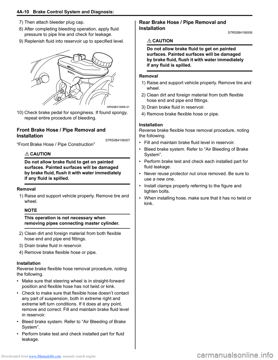
7) Then attach bleeder plug cap.
8) After completing bleeding operation, apply fluid pressure to pipe line and check for leakage.
9) Replenish fluid into reserv oir up to specified level.
10) Check brake pedal for sponginess. If found spongy, repeat entire procedure of bleeding.
Front Brake Hose / Pipe Removal and
Installation
S7RS0B4106007
“Front Brake Hose / Pipe Construction”
CAUTION!
Do not allow brake fluid to get on painted
surfaces. Painted surfaces will be damaged
by brake fluid, flush it with water immediately
if any fluid is spilled.
Removal
1) Raise and support vehicle properly. Remove tire and wheel.
NOTE
This operation is not necessary when
removing pipes connecting master cylinder.
2) Clean dirt and foreign mate rial from both flexible
hose end and pipe end fittings.
3) Drain brake fluid in reservoir.
4) Remove brake flexible hose or pipe.
Installation
Reverse brake flexible hose removal procedure, noting
the following.
• Make sure that steering wh eel is in straight-forward
position and flexible hose has not twist or kink.
• Check to make sure that flexible hose doesn’t contact any part of suspension, both in extreme right and
extreme left turn conditions. If it does at any point,
remove and correct. Fill and maintain brake fluid level
in reservoir.
• Bleed brake system. Refer to “Air Bleeding of Brake System”.
• Perform brake test and check installed part for fluid leakage.
Rear Brake Hose / Pipe Removal and
Installation
S7RS0B4106008
CAUTION!
Do not allow brake fluid to get on painted
surfaces. Painted surfaces will be damaged
by brake fluid, flush it with water immediately
if any fluid is spilled.
Removal
1) Raise and support vehicle properly. Remove tire and wheel.
2) Clean dirt and foreign material from both flexible hose end and pipe end fittings.
3) Drain brake fluid in reservoir.
4) Remove brake flexible hose or pipe.
Installation
Reverse brake flexible hose removal procedure, noting
the following.
• Fill and maintain brake fluid level in reservoir.
• Bleed brake system. Refer to “Air Bleeding of Brake System”.
• Perform brake test and check each installed part for fluid leakage.
• Never reuse protector nut once removed. Be sure to use a new one.
• Install clamps properly referring to the figure and tighten bolts.
• When installing hose, make sure that it has no twist or
kink.
I4RS0B410006-01
Page 534 of 1496

Downloaded from www.Manualslib.com manuals search engine 4C-10 Rear Brakes:
• Using micrometer, measure thickness of brake disc.If limit value is exceeded, replace brake disc.
Rear brake disc thickness
Standard: 9 mm (0.354 in.)
Limit: 8 mm (0.315 in.)
Specifications
Tightening Torque SpecificationsS7RS0B4307001
NOTE
The specified tightening torque is also described in the following.
“Rear Disc Brake Components”
Reference:
For the tightening torque of fastener not specified in this section, refer to “Fasteners Information in Section 0A”.
I6RS0B431032-01
Fastening part Tightening torque
Note
N ⋅mkgf-mlb-ft
Caliper pin bolt 23 2.3 17 �)
Wheel bolt 85 8.5 61.5 �) / �) / �)
Brake caliper carrier bolt 60 6.0 43.5 �)
Flexible hose joint bolt 23 2.3 17.0 �)
Parking nut 27 2.7 19.5 �)
Brake pipe flare nut 16 1.6 12.0 �)
Caliper carrier bolt 60 6.0 43.5 �)
Page 544 of 1496
Downloaded from www.Manualslib.com manuals search engine 4E-5 ABS:
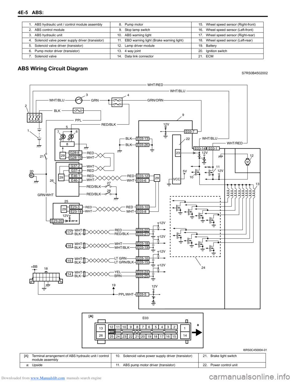
ABS Wiring Circuit DiagramS7RS0B4502002
1. ABS hydraulic unit / control module assembly 8.
Pump motor 15. Wheel speed sensor (Right-front)
2. ABS control module 9. Stop lamp switch 16. Wheel speed sensor (Left-front)
3. ABS hydraulic unit 10. ABS warning light 17. Wheel speed sensor (Right-rear)
4. Solenoid valve power supply driver (transistor) 11. EBD warnin g light (Brake warning light) 18. Wheel speed sensor (Left-rear)
5. Solenoid valve driver (transistor) 12. Lamp driver module 19. Battery
6. Pump motor driver (transistor) 13. 4 way joint 20. Ignition switch
7. Solenoid valve 14. Data link connector 21. ECM
[A]
14
1516171819202122232425 1
23456789101112
13
26 E03
a
WHT/BLU
BLKWHT/BLU
M
12V
9
10 11 12
13
BLKE03-14E03-1
E03-13
E03-26
YELBRN
14E03-24
LT GRN/BLKLT GRN
15
WHTWHT/BLK
16
RED
WHTBLK
WHTBLK
WHTBLK
WHTBLKRED/BLK
17
12V
PPL/WHT
18E03-5
1912V
5V
12V
23
24
VCC22
E03-25
E03-15E03-16
E03-19E03-18
E03-22E03-21
WHT/RED
WHT/RED
+BB
GRN/ORN
E03-7
WHT/BLUGRN
1
2
3
4
8
RED/BLK
E03-12
E03-6
RED
WHTE03-10E03-8
REDWHT
20 7
6
529
29
G28-8
G28-10
25
29
E23-3E23-18
GRN/WHT
21
PPL
12V
E23-20
12V
12V
12V
12V
REDWHTE46-1
E46-2
BLK
RED/BLK
RED/BLK
RED
RED
WHT
WHT
27
28
26
29
G37-2
G37-4
REDWHT
I6RS0C450004-01
[A]: Terminal arrangement of ABS hydraulic unit / control module assembly 10. Solenoid valve power supply driver
(transistor) 21. Brake light switch
a: Upside 11. ABS pump motor driver (transistor) 22. Power control unit