2007 SUZUKI SWIFT 0b -10
[x] Cancel search: 0b -10Page 282 of 1496
Downloaded from www.Manualslib.com manuals search engine 1C-10 Engine Electrical Devices:
Knock Sensor Removal and InstallationS7RS0B1306016
Removal1) Disconnect negative (–) cable at battery.
2) Hoist vehicle.
3) Remove right side drive shaft referring to “Front Drive Shaft Assembly Removal and Installation in
Section 3A”.
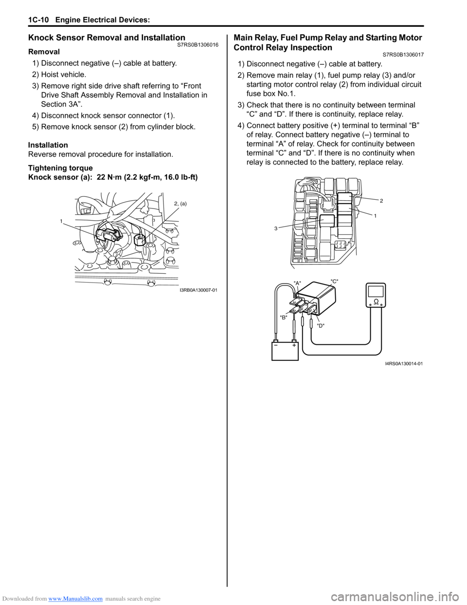
4) Disconnect knock sensor connector (1).
5) Remove knock sensor (2) from cylinder block.
Installation
Reverse removal procedure for installation.
Tightening torque
Knock sensor (a): 22 N· m (2.2 kgf-m, 16.0 lb-ft)
Main Relay, Fuel Pump Relay and Starting Motor
Control Relay Inspection
S7RS0B1306017
1) Disconnect negative (–) cable at battery.
2) Remove main relay (1), fuel pump relay (3) and/or
starting motor control relay (2) from individual circuit
fuse box No.1.
3) Check that there is no continuity between terminal “C” and “D”. If there is continuity, replace relay.
4) Connect battery positive (+ ) terminal to terminal “B”
of relay. Connect battery negative (–) terminal to
terminal “A” of relay. Ch eck for continuity between
terminal “C” and “D”. If t here is no continuity when
relay is connected to the battery, replace relay.
1 2, (a)
I3RB0A130007-01
"D"
"B" "A"
"C"
2
1
3
I4RS0A130014-01
Page 295 of 1496
Downloaded from www.Manualslib.com manuals search engine Engine Mechanical: 1D-10
Air Cleaner Element Inspection and CleaningS7RS0B1406003
Inspection
Check air cleaner element for dirt. Replace excessive
dirty element.
Cleaning
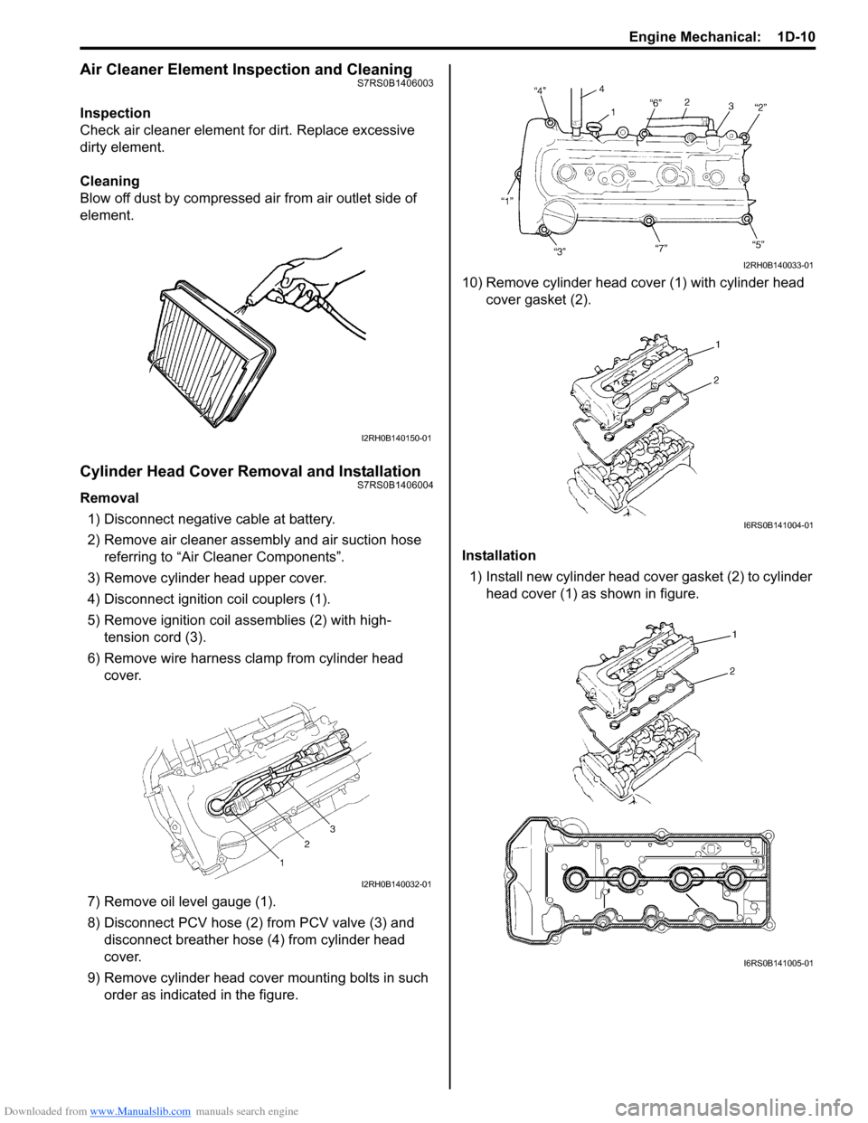
Blow off dust by compressed air from air outlet side of
element.
Cylinder Head Cover Removal and InstallationS7RS0B1406004
Removal1) Disconnect negative cable at battery.
2) Remove air cleaner assembly and air suction hose referring to “Air Cleaner Components”.
3) Remove cylinder head upper cover.
4) Disconnect ignition coil couplers (1).
5) Remove ignition coil assemblies (2) with high- tension cord (3).
6) Remove wire harness clamp from cylinder head cover.
7) Remove oil level gauge (1).
8) Disconnect PCV hose (2) from PCV valve (3) and disconnect breather hose (4) from cylinder head
cover.
9) Remove cylinder head cove r mounting bolts in such
order as indicated in the figure. 10) Remove cylinder head cover (1) with cylinder head
cover gasket (2).
Installation 1) Install new cylinder head cover gasket (2) to cylinder
head cover (1) as shown in figure.
I2RH0B140150-01
I2RH0B140032-01
I2RH0B140033-01
I6RS0B141004-01
I6RS0B141005-01
Page 362 of 1496
Downloaded from www.Manualslib.com manuals search engine 1E-10 Engine Lubrication System:
Radial clearance
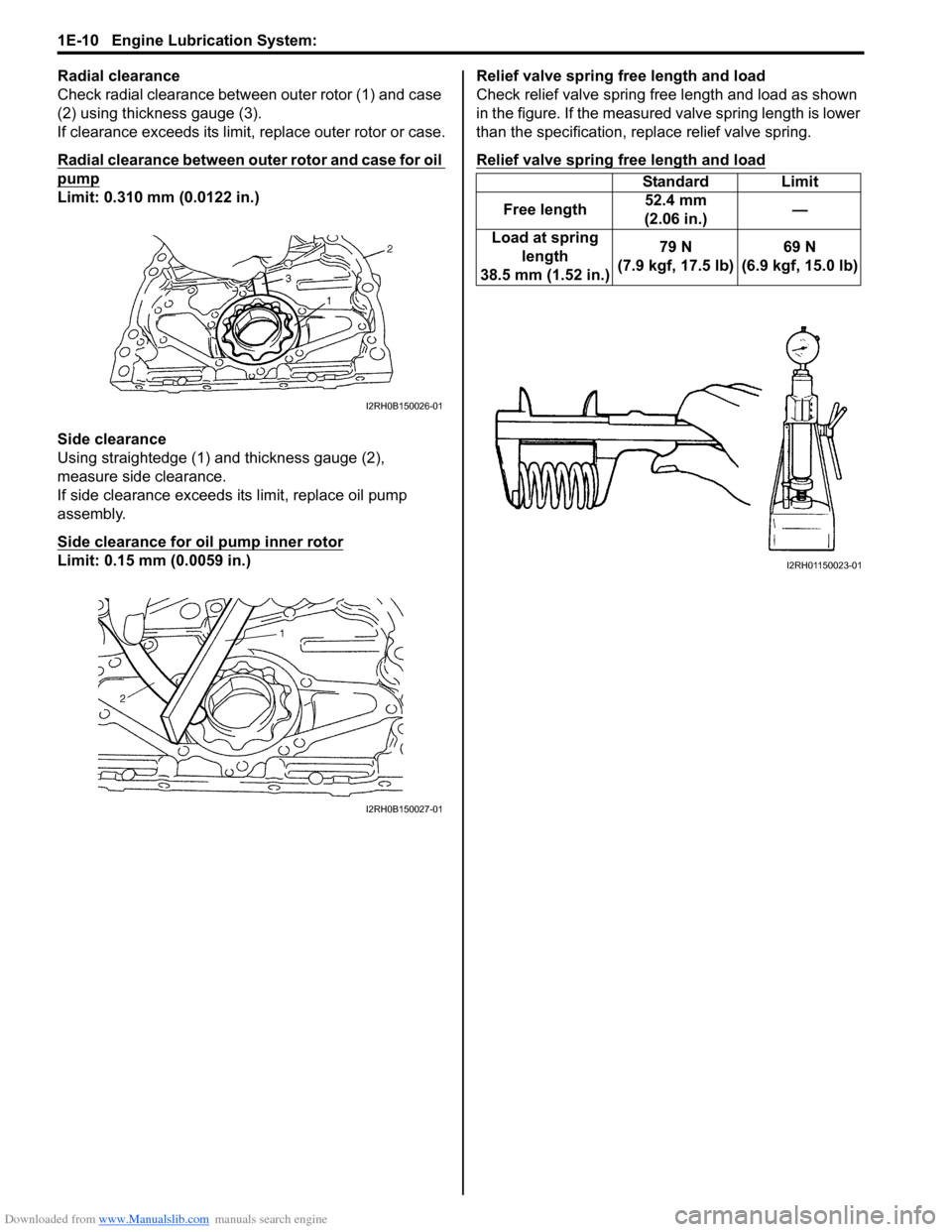
Check radial clearance between outer rotor (1) and case
(2) using thickness gauge (3).
If clearance exceeds its limit, replace outer rotor or case.
Radial clearance between outer rotor and case for oil
pump
Limit: 0.310 mm (0.0122 in.)
Side clearance
Using straightedge (1) and thickness gauge (2),
measure side clearance.
If side clearance exceeds its limit, replace oil pump
assembly.
Side clearance for oil pump inner rotor
Limit: 0.15 mm (0.0059 in.)Relief valve spring free length and load
Check relief valve spring free length and load as shown
in the figure. If the measured valve spring length is lower
than the specification, replace relief valve spring.
Relief valve spring free length and load
I2RH0B150026-01
I2RH0B150027-01
Standard Limit
Free length 52.4 mm
(2.06 in.) —
Load at spring length
38.5 mm (1.52 in.) 79 N
(7.9 kgf, 17.5 lb) 69 N
(6.9 kgf, 15.0 lb)
I2RH01150023-01
Page 363 of 1496

Downloaded from www.Manualslib.com manuals search engine Engine Lubrication System: 1E-11
Specifications
Tightening Torque SpecificationsS7RS0B1507001
NOTE
The specified tightening torque is also described in the following.
“Heat Exchanger Components”
“Oil Pan and Oil Pump Strainer Components”
“Oil Pump Components”
Reference:
For the tightening torque of fastener not specified in this section, refer to “Fasteners Information in Section 0A”.
Special Tools and Equipment
Recommended Service MaterialS7RS0B1508001
NOTE
Required service material is also described in the following.
“Heat Exchanger Components”
“Oil Pan and Oil Pump Strainer Components”
“Oil Pump Components”
Special ToolS7RS0B1508002
Fastening part Tightening torque
Note
N ⋅mkgf-mlb-ft
Oil pressure switch 13 1.3 9.5 �)
Heat exchanger stand bolt 22 2.2 16.0 �)
Oil pump strainer bolt 11 1.1 8.0 �)
Oil pump strainer bracket bolt 11 1.1 8.0 �)
Oil pan bolt (M6) 11 1.1 8.0 �)
Oil pan bolt (M10) 55 5.5 40.0 �)
Oil pan nut 11 1.1 8.0 �)
Oil pan drain plug 35 3.5 25.5 �)
Transaxle stiffener bolt 55 5.5 40.0 �)
Oil pump rotor plate bolt 11 1.1 8.0 �)
MaterialSUZUKI recommended product or Specification Note
Sealant SUZUKI Bond No.1217G P/No.: 99000–31260�)
09915–77310 09915–78211
Oil pressure gauge (0-10kg/
cm2) Oil pressure gauge
attachment
�)�)
Page 373 of 1496
Downloaded from www.Manualslib.com manuals search engine Engine Cooling System: 1F-10
Radiator Cooling Fan Removal and InstallationS7RS0B1606011
Removal1) Disconnect negative (–) cable at battery.
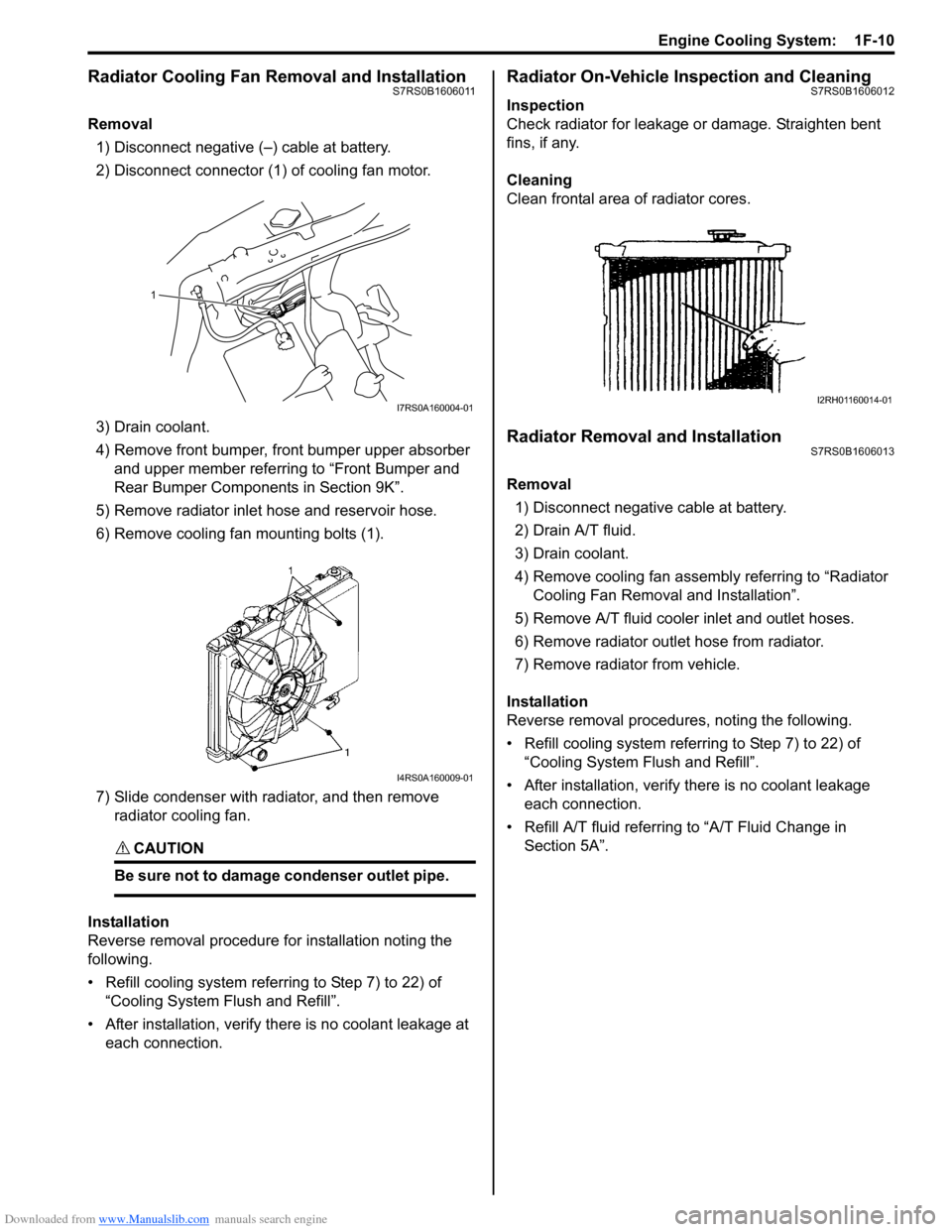
2) Disconnect connector (1) of cooling fan motor.
3) Drain coolant.
4) Remove front bumper, front bumper upper absorber and upper member referring to “Front Bumper and
Rear Bumper Componen ts in Section 9K”.
5) Remove radiator inlet hose and reservoir hose.
6) Remove cooling fan mounting bolts (1).
7) Slide condenser with radiator, and then remove radiator cooling fan.
CAUTION!
Be sure not to damage condenser outlet pipe.
Installation
Reverse removal procedure for installation noting the
following.
• Refill cooling system referring to Step 7) to 22) of “Cooling System Fl ush and Refill”.
• After installation, verify there is no coolant leakage at each connection.
Radiator On-Vehicle Inspection and CleaningS7RS0B1606012
Inspection
Check radiator for leakage or damage. Straighten bent
fins, if any.
Cleaning
Clean frontal area of radiator cores.
Radiator Removal and InstallationS7RS0B1606013
Removal
1) Disconnect negative cable at battery.
2) Drain A/T fluid.
3) Drain coolant.
4) Remove cooling fan assemb ly referring to “Radiator
Cooling Fan Removal and Installation”.
5) Remove A/T fluid cooler inlet and outlet hoses.
6) Remove radiator outlet hose from radiator.
7) Remove radiator from vehicle.
Installation
Reverse removal procedures, noting the following.
• Refill cooling system referrin g to Step 7) to 22) of
“Cooling System Flush and Refill”.
• After installation, verify there is no coolant leakage each connection.
• Refill A/T fluid referring to “A/T Fluid Change in
Section 5A”.
1
I7RS0A160004-01
I4RS0A160009-01
I2RH01160014-01
Page 385 of 1496

Downloaded from www.Manualslib.com manuals search engine Fuel System: 1G-10
4) Install suitable vinyl tube onto injector nozzle to
prevent fuel from splashing out when injecting.
5) Put graduated cylinder under injector.
6) Operate fuel pump and apply fuel pressure to
injector as follows:
a) When using scan tool:
i) Connect scan tool to DLC with ignition switch OFF.
ii) Turn ignition switch ON, clear DTC and select “MISC TEST” mode on scan tool.
iii) Turn fuel pump ON by using scan tool.
Special tool
(A): SUZUKI scan tool
b) When not using scan tool: i) Remove fuel pump relay from connector.
ii) Connect two terminals of relay connector using service wire (1) as shown in figure.
CAUTION!
Check to make sure that connection is made
between correct terminals. Wrong
connection can cause damage to ECM, wire
harness, etc.
iii) Turn ignition switch ON. 7) Apply battery voltage to in
jector (1) for 15 seconds
and measure injected fuel volume with graduated
cylinder. Test each injector two or three times. If not
within specification, replace injector.
Injected fuel volume
43 – 47 cc/15 sec. (1.45/1.51 – 1.58/1.65 US/lmp
oz/15 sec.)
8) Check fuel leakage from injector nozzle. Do not operate injector for this check (but fuel pump should
be at work). If fuel leaks (1) more than the following
specifications, replace.
Fuel leakage
Less than 1 drop/min.
Fuel Filler Cap InspectionS7RS0B1706010
WARNING!
Before starting the following procedure, be
sure to observe “Precautions on Fuel System
Service” in order to reduce the risk or fire
and personal injury.
Remove cap (1), and che ck gasket for even filler neck
imprint, and deterioration or any damage. If gasket (2) is
in malcondition, replace cap.
NOTE
If cap requires replacement, only a cap with
the same features should be used. Failure to
use correct cap can result in fire and
personal injury.
(A)I4RS0A170021-01
1
I4RS0A170006-02
I2RH0B170013-01
I2RH01170008-01
Page 420 of 1496
Downloaded from www.Manualslib.com manuals search engine 1J-10 Charging System:
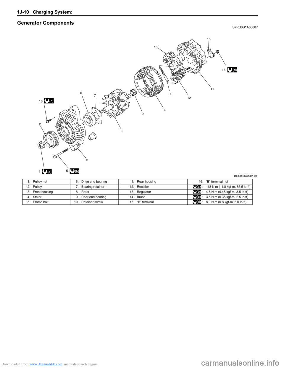
Generator ComponentsS7RS0B1A06007
1211
13
14
(a)(b)
(c)
(d)
1 2
3 4
56
7
89
10 15
16
I4RS0B1A0007-01
1. Pulley nut 6. Drive end bearing 11. Rear housing 16. “B” terminal nut
2. Pulley 7. Bearing retainer 12. Rectifier : 118 N⋅m (11.8 kgf-m, 85.5 lb-ft)
3. Front housing 8. Rotor 13. Regulator : 4.5 N⋅m (0.45 kgf-m, 3.5 lb-ft)
4. Stator 9. Rear end bearing 14. Brush : 3.5 N⋅m (0.35 kgf-m, 2.5 lb-ft)
5. Frame bolt 10. Retainer screw 15. “B” terminal : 8.0 N⋅m (0.8 kgf-m, 6.0 lb-ft)
Page 429 of 1496
Downloaded from www.Manualslib.com manuals search engine Table of Contents 2- i
2
Section 2
CONTENTS
Suspension
Precautions ................................................. 2-1
Precautions............................................................. 2-1
Precautions on Suspension .................................. 2-1
Suspension General Dia gnosis.............. 2A-1
Diagnostic Information and Procedures ............ 2A-1
Suspension, Wheels and Tires Symptom Diagnosis .......................................................... 2A-1
Front Suspension ........... ......................... 2B-1
General Description ............................................. 2B-1
Front Suspension Construction ........................... 2B-1
Front Wheel Alignment Cons truction .................. 2B-2
Repair Instructions .............................................. 2B-2 Front Wheel Alignment Inspection and Adjustment ........................................................ 2B-2
Front Strut Assembly Comp onents ..................... 2B-4
Front Strut Assembly Removal and Installation ......................................................... 2B-4
Front Strut Assembly Disassembly and Assembly .......................................................... 2B-6
Front Strut Assembly Chec k ............................... 2B-7
Front Wheel Hub and Steering Knuckle Components...................................................... 2B-8
Front Wheel Hub, Steering Knuckle and Wheel Bearing Removal and Installation .......... 2B-8
Front Wheel Hub, Disc, Nut and Bearing Check .............................................................. 2B-12
Suspension Control Arm / Bushing Removal and Installation ................................................ 2B-12
Suspension Control Arm / Bushing Disassembly and Assembly ............................ 2B-13
Suspension Control Arm / Steering Knuckle Check .............................................................. 2B-14
Suspension Control Arm Bushing Check .......... 2B-14
Suspension Control Arm Joint Check ............... 2B-14
Front Suspension Fram e, Stabilizer Bar and/
or Bushings Components................................ 2B-15
Front Suspension Fram e, Stabilizer Bar and/
or Bushings Removal and Installation ............. 2B-15
Front Suspension Frame Ch eck ....................... 2B-19
Front Stabilizer Bar, Bushing and/or Joint Check .............................................................. 2B-19
Front Suspension Fastener s Check .................. 2B-19
Specifications ..................................................... 2B-20 Tightening Torque Specifications ...................... 2B-20
Special Tools and Equipmen t ...........................2B-21
Special Tool ...................................................... 2B-21
Rear Suspension ............ ......................... 2C-1
General Description .............................................2C-1
Rear Suspension Construction ...........................2C-1
Repair Instructions ........... ...................................2C-2
Rear Wheel Alignment Inspection .......................2C-2
Rear Shock Absorber Removal and Installation .........................................................2C-2
Rear Shock Absorber Ins pection ........................2C-3
Rear Shock Absorber Bush Removal and Installation .........................................................2C-4
Rear Shock Absorber Bush Inspection ...............2C-4
Rear Coil Spring Removal and Installation .........2C-4
Spring Upper Seat / Spring Lower Seat Inspection ..........................................................2C-5
Spring Upper Seat and Lower Seat Removal and Installation ..................................................2C-6
Rear Axle Removal and Inst allation ....................2C-6
Trailing Arm, Rear Axle and Coil Spring Inspection ..........................................................2C-9
Rear Axle Bush Inspection ..................................2C-9
Rear Wheel Hub Components ..........................2C-10
Rear Wheel Hub Removal an d Installation .......2C-10
Rear Wheel Disc, bolt and Bearing Inspection ..2C-11
Spindle Removal and Installation ......................2C-12
Spindle Inspection .............................................2C-13
Rear Suspension Fasteners Inspection ............2C-13
Specifications .................... .................................2C-13
Tightening Torque Specifications ......................2C-13
Special Tools and Equipmen t ...........................2C-13
Special Tool ......................................................2C-13
Wheels and Tires ............ ......................... 2D-1
Precautions...........................................................2D-1
Precaution for Emergency Flat Tire Repair Kit ....2D-1
General Description .............................................2D-1 Tires Description .................................................2D-1
Wheels Description .............................................2D-2
Irregular and/or Premature Wear Description .....2D-3
Wear Indicators Description ................................2D-3
Radial Tire Waddle Description...........................2D-4
Radial Tire Lead / Pull Description ......................2D-5