2007 SUZUKI SWIFT 12 volt
[x] Cancel search: 12 voltPage 1322 of 1496
Downloaded from www.Manualslib.com manuals search engine 9D-5 Wipers / Washers:
Windshield Wiper Motor InspectionS7RS0B9406005
NOTE
Make sure that battery voltage is 12 V or
more.
1) Disconnect negative (–) cable at battery.
2) Remove windshield wiper arms with wiper blades
referring to “Windshield Wiper Removal and
Installation”.
3) Remove cowl top garnish referring to “Cowl Top Components in Section 9K”.
4) Disconnect coupler from windshield wiper motor.
5) Reinstall windshield wiper arms with wiper blade. For
details, refer to Step 4) of “Installation” in “Windshield
Wiper Removal and Installation”.
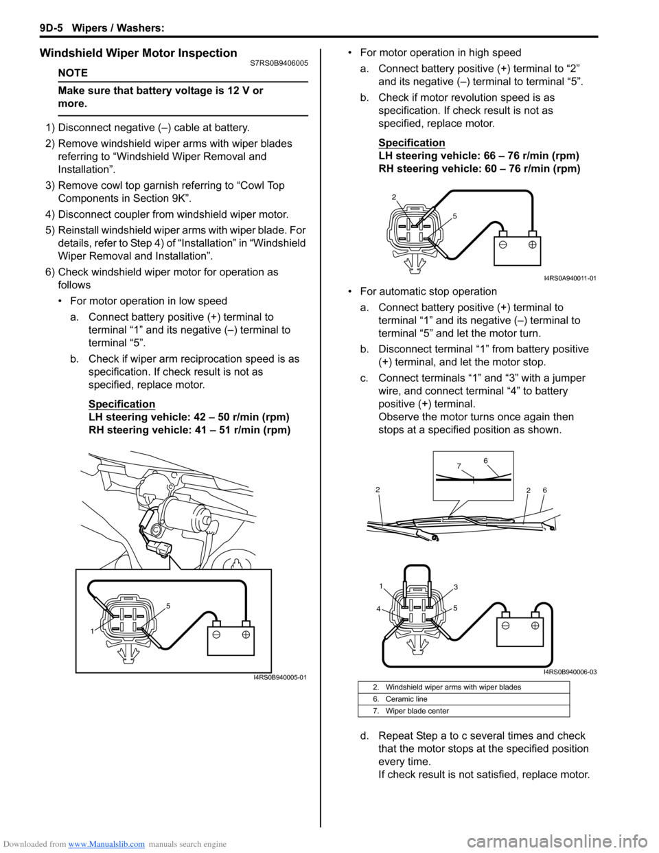
6) Check windshield wiper motor for operation as
follows
• For motor operation in low speed
a. Connect battery positive (+) terminal to terminal “1” and its negative (–) terminal to
terminal “5”.
b. Check if wiper arm reciprocation speed is as specification. If check result is not as
specified, replace motor.
Specification
LH steering vehicle: 42 – 50 r/min (rpm)
RH steering vehicle: 41 – 51 r/min (rpm) • For motor operation in high speed
a. Connect battery positive (+) terminal to “2” and its negative (–) terminal to terminal “5”.
b. Check if motor revolution speed is as specification. If chec k result is not as
specified, replace motor.
Specification
LH steering vehicle: 66 – 76 r/min (rpm)
RH steering vehicle: 60 – 76 r/min (rpm)
• For automatic stop operation a. Connect battery positive (+) terminal to terminal “1” and its negative (–) terminal to
terminal “5” and let the motor turn.
b. Disconnect terminal “1” from battery positive (+) terminal, and let the motor stop.
c. Connect terminals “1” and “3” with a jumper wire, and connect terminal “4” to battery
positive (+) terminal.
Observe the motor turns once again then
stops at a specified position as shown.
d. Repeat Step a to c several times and check that the motor stops at the specified position
every time.
If check result is not satisfied, replace motor.
1 5
I4RS0B940005-012. Windshield wiper arms with wiper blades
6. Ceramic line
7. Wiper blade center
2
5
I4RS0A940011-01
4 5
31
6
6
7
2
2
I4RS0B940006-03
Page 1324 of 1496
Downloaded from www.Manualslib.com manuals search engine 9D-7 Wipers / Washers:
Rear Wiper Motor InspectionS7RS0B9406007
NOTE
Make sure that battery voltage is 12 V or
more.
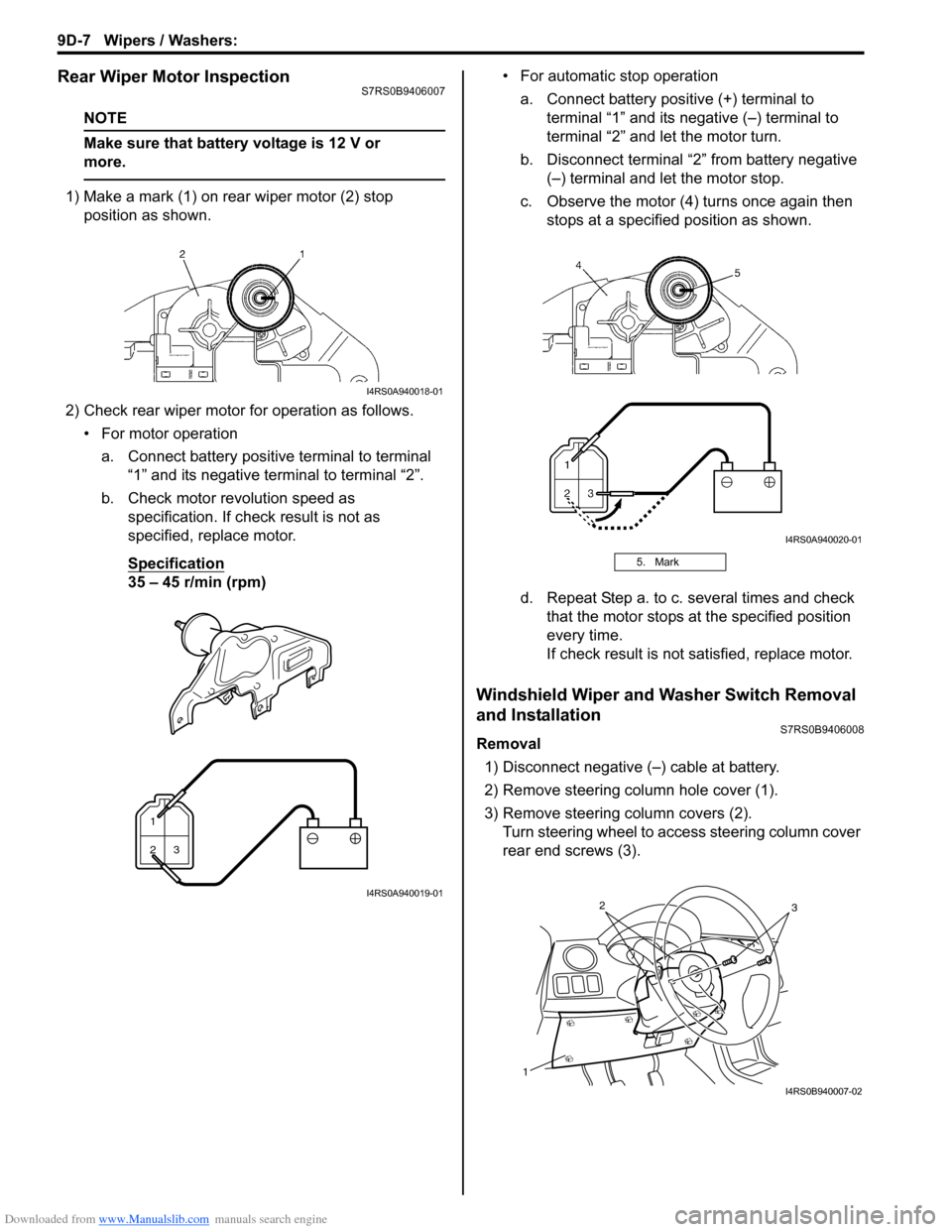
1) Make a mark (1) on rear wiper motor (2) stop position as shown.
2) Check rear wiper motor for operation as follows. • For motor operationa. Connect battery positive terminal to terminal “1” and its negative terminal to terminal “2”.
b. Check motor revolution speed as specification. If check result is not as
specified, replace motor.
Specification
35 – 45 r/min (rpm) • For automatic stop operation
a. Connect battery positive (+) terminal to terminal “1” and its negative (–) terminal to
terminal “2” and let the motor turn.
b. Disconnect terminal “2” from battery negative (–) terminal and let the motor stop.
c. Observe the motor (4) turns once again then stops at a specified position as shown.
d. Repeat Step a. to c. several times and check that the motor stops at the specified position
every time.
If check result is not satisfied, replace motor.
Windshield Wiper and Washer Switch Removal
and Installation
S7RS0B9406008
Removal
1) Disconnect negative (–) cable at battery.
2) Remove steering column hole cover (1).
3) Remove steering column covers (2). Turn steering wheel to a ccess steering column cover
rear end screws (3).
I4RS0A940018-01
1
23
I4RS0A940019-01
5. Mark
I4RS0A940020-01
1
32
I4RS0B940007-02
Page 1325 of 1496
Downloaded from www.Manualslib.com manuals search engine Wipers / Washers: 9D-8
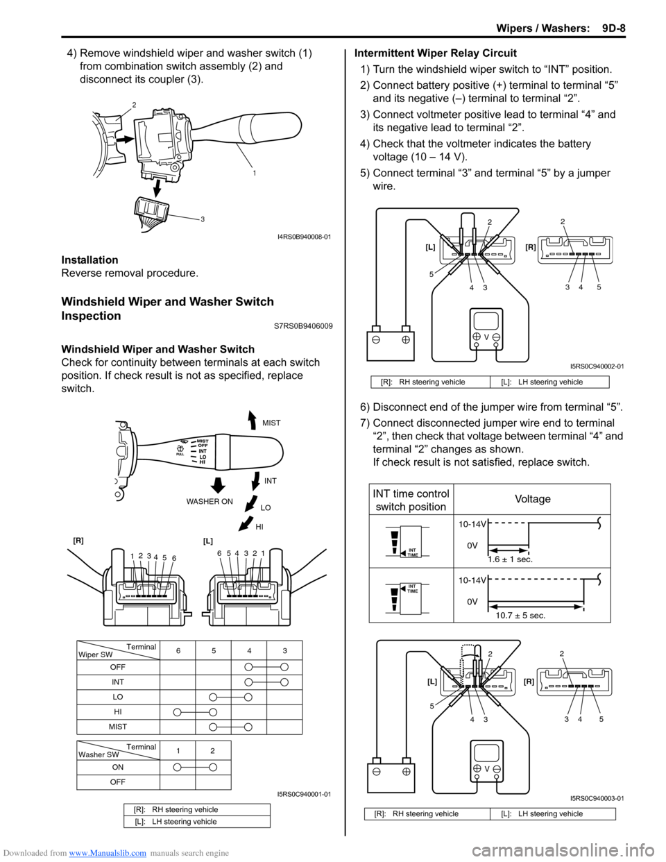
4) Remove windshield wiper and washer switch (1) from combination swit ch assembly (2) and
disconnect its coupler (3).
Installation
Reverse removal procedure.
Windshield Wiper and Washer Switch
Inspection
S7RS0B9406009
Windshield Wiper and Washer Switch
Check for continuity between terminals at each switch
position. If check result is not as specified, replace
switch. Intermittent Wiper Relay Circuit
1) Turn the windshield wiper switch to “INT” position.
2) Connect battery positive (+ ) terminal to terminal “5”
and its negative (–) terminal to terminal “2”.
3) Connect voltmeter positive lead to terminal “4” and its negative lead to terminal “2”.
4) Check that the voltmeter indicates the battery voltage (10 – 14 V).
5) Connect terminal “3” and terminal “5” by a jumper wire.
6) Disconnect end of the jumper wire from terminal “5”.
7) Connect disconnected jumper wire end to terminal “2”, then check that voltage between terminal “4” and
terminal “2” changes as shown.
If check result is not satisfied, replace switch.
[R]: RH steering vehicle
[L]: LH steering vehicle
1
2
3
I4RS0B940008-01
Terminal
Wiper SW
OFF
INT 6543
MIST
Terminal
Washer SW
OFF 12
ONLO
HI
654321
MIST
INT
LO
HI
WASHER ON
1
2
3
4 5 6
[R]
[L]
I5RS0C940001-01
[R]: RH steering vehicle [L]: LH steering vehicle
[R]: RH steering vehicle [L]: LH steering vehicle
V
2
34
52
34 5
[L] [R]
I5RS0C940002-01
V
INT
TIME
INT
TIME
INT time control
switch position Voltage
10-14V
0V 1.6 ± 1 sec.
10-14V
0V 10.7 ± 5 sec.
2
34
52
34 5
[L]
[R]
I5RS0C940003-01
Page 1326 of 1496
Downloaded from www.Manualslib.com manuals search engine 9D-9 Wipers / Washers:
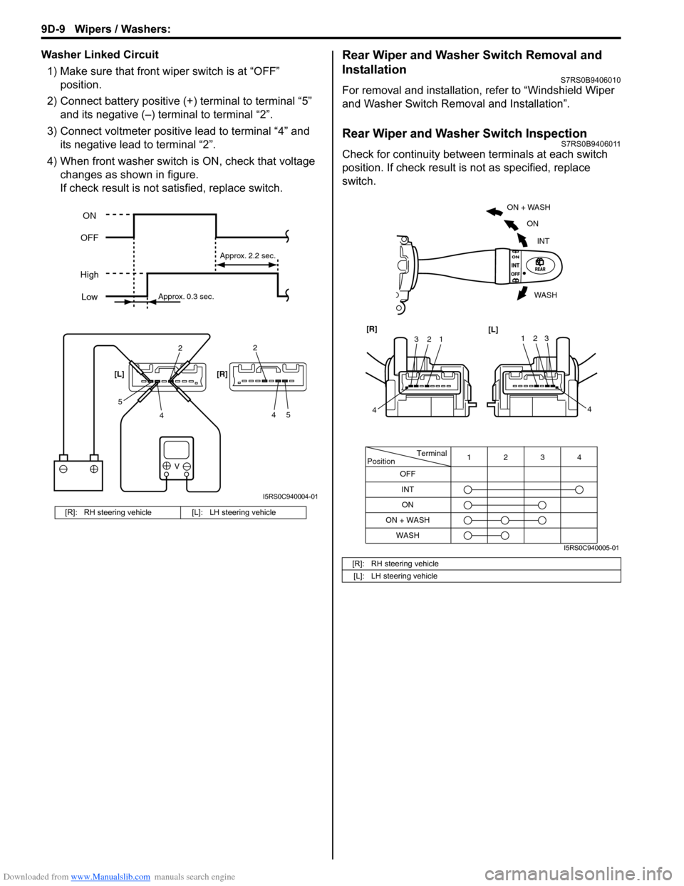
Washer Linked Circuit1) Make sure that front wiper switch is at “OFF” position.
2) Connect battery positive (+ ) terminal to terminal “5”
and its negative (–) terminal to terminal “2”.
3) Connect voltmeter positive lead to terminal “4” and its negative lead to terminal “2”.
4) When front washer switch is ON, check that voltage
changes as shown in figure.
If check result is not satisfied, replace switch.Rear Wiper and Washer Switch Removal and
Installation
S7RS0B9406010
For removal and installation, refer to “Windshield Wiper
and Washer Switch Removal and Installation”.
Rear Wiper and Washer Switch InspectionS7RS0B9406011
Check for continuity between terminals at each switch
position. If check result is not as specified, replace
switch.
[R]: RH steering vehicle [L]: LH steering vehicle
V
2
4
52
45
[L] [R]
ON
OFF
High Low
Approx. 0.3 sec. Approx. 2.2 sec.
I5RS0C940004-01
[R]: RH steering vehicle
[L]: LH steering vehicle
Terminal
Position
OFF
INT 4
3
12
WASH ON
ON + WASH
ON + WASH
INT
ON
WASH
123
4
[R]
[L]123
4
I5RS0C940005-01
Page 1342 of 1496
Downloaded from www.Manualslib.com manuals search engine 9E-15 Glass / Windows / Mirrors:
Rear End Door Window Defogger Wire
Inspection
S7RS0B9506014
NOTE
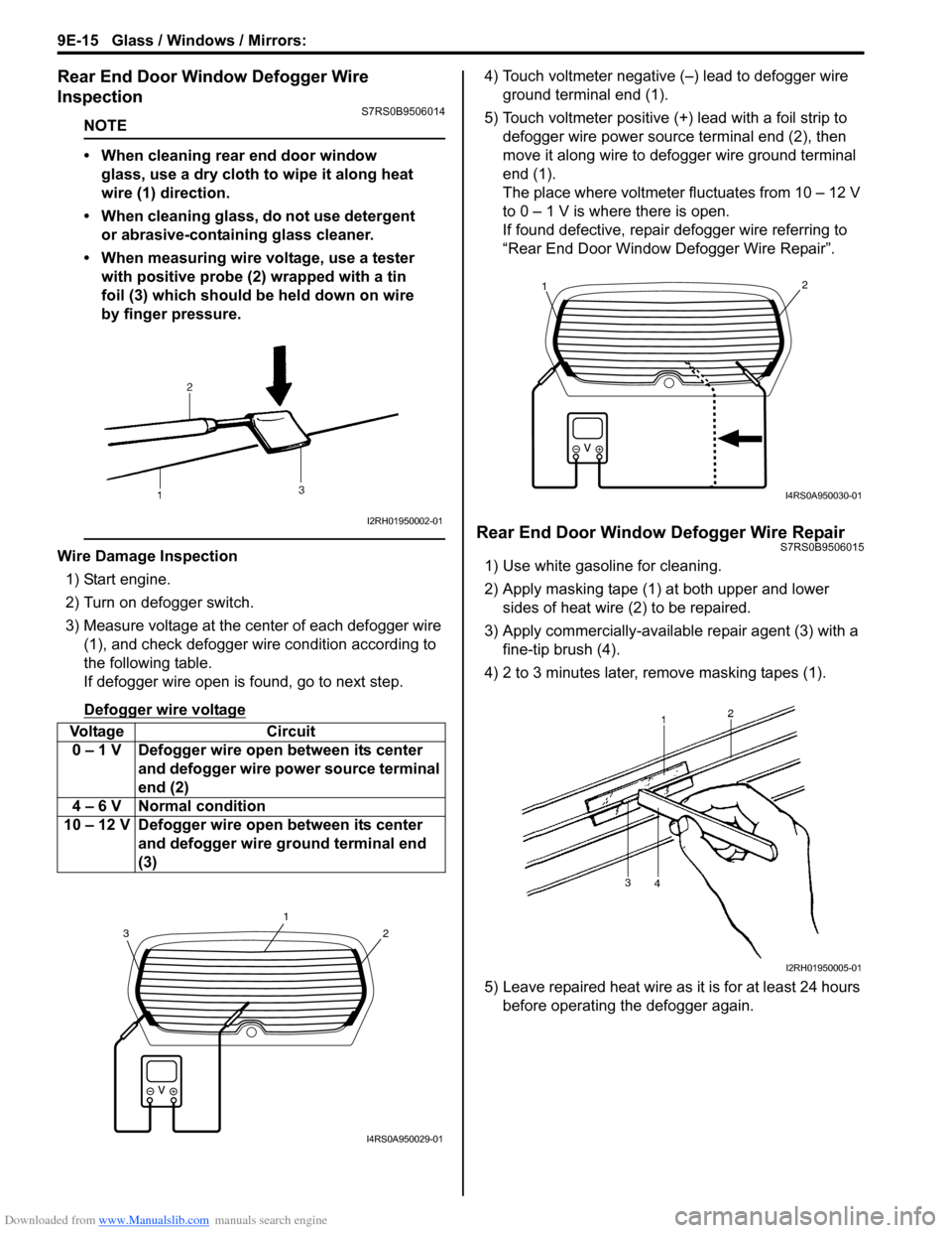
• When cleaning rear end door window glass, use a dry cloth to wipe it along heat
wire (1) direction.
• When cleaning glass, do not use detergent or abrasive-containing glass cleaner.
• When measuring wire voltage, use a tester with positive probe (2) wrapped with a tin
foil (3) which should be held down on wire
by finger pressure.
Wire Damage Inspection
1) Start engine.
2) Turn on defogger switch.
3) Measure voltage at the center of each defogger wire (1), and check defogger wire condition according to
the following table.
If defogger wire open is found, go to next step.
Defogger wire voltage
4) Touch voltmeter negative (–) lead to defogger wire ground terminal end (1).
5) Touch voltmeter positive (+) lead with a foil strip to defogger wire power source terminal end (2), then
move it along wire to defogger wire ground terminal
end (1).
The place where voltmeter fluctuates from 10 – 12 V
to 0 – 1 V is where there is open.
If found defective, repair defogger wire referring to
“Rear End Door Window Defogger Wire Repair”.
Rear End Door Window Defogger Wire RepairS7RS0B9506015
1) Use white gasoline for cleaning.
2) Apply masking tape (1) at both upper and lower sides of heat wire (2) to be repaired.
3) Apply commercially-available repair agent (3) with a fine-tip brush (4).
4) 2 to 3 minutes later, remove masking tapes (1).
5) Leave repaired heat wire as it is for at least 24 hours before operating the defogger again.
Voltage Circuit
0 – 1 V Defogger wire open between its center and defogger wire power source terminal
end (2)
4 – 6 V Normal condition
10 – 12 V Defogger wire open between its center and defogger wire ground terminal end
(3)
I2RH01950002-01
2
1
3
I4RS0A950029-01
21
I4RS0A950030-01
I2RH01950005-01
Page 1346 of 1496
Downloaded from www.Manualslib.com manuals search engine 9E-19 Glass / Windows / Mirrors:
Power Door Mirror Actuator InspectionS7RS0B9506021
1) Remove front door trim referring to step 1) to 3) of “Front Door Glass Removal and Installation”.
2) Disconnect door mirror coupler (1).
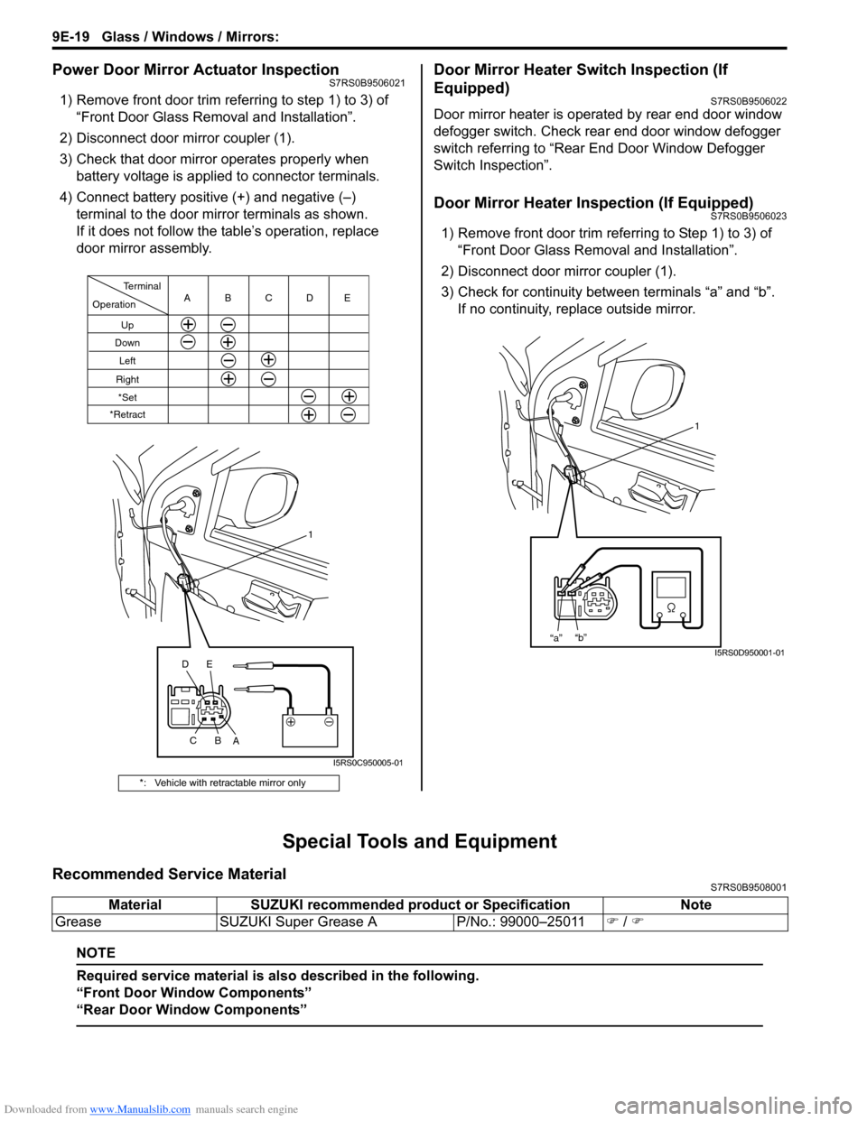
3) Check that door mirror operates properly when battery voltage is applied to connector terminals.
4) Connect battery positive (+) and negative (–) terminal to the door mirror terminals as shown.
If it does not follow the table’s operation, replace
door mirror assembly.
Door Mirror Heater Switch Inspection (If
Equipped)
S7RS0B9506022
Door mirror heater is operated by rear end door window
defogger switch. Check rear end door window defogger
switch referring to “Rear End Door Window Defogger
Switch Inspection”.
Door Mirror Heater Inspection (If Equipped)S7RS0B9506023
1) Remove front door trim refe rring to Step 1) to 3) of
“Front Door Glass Removal and Installation”.
2) Disconnect door mirror coupler (1).
3) Check for continuity between terminals “a” and “b”. If no continuity, replace outside mirror.
Special Tools and Equipment
Recommended Service MaterialS7RS0B9508001
NOTE
Required service material is also described in the following.
“Front Door Window Components”
“Rear Door Window Components”
*: Vehicle with retractable mirror only
Operation
Terminal
Up
Down
Left
RightCBA
1
C B
A
*Set
*Retract
DE
DE
I5RS0C950005-01
1
“a” “b”
I5RS0D950001-01
Material
SUZUKI recommended product or Specification Note
Grease SUZUKI Super Grease A P/No.: 99000–25011�) / �)
Page 1361 of 1496
Downloaded from www.Manualslib.com manuals search engine Security and Locks: 9F-15
Keyless Entry Receiver and Its Circuit InspectionS7RS0B9606018
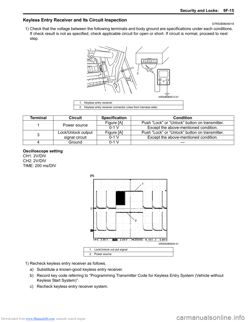
1) Check that the voltage between the following terminals and body ground are specifications under each conditions.
If check result is not as specified, ch eck applicable circuit for open or short. If circuit is normal, proceed to next
step.
Oscilloscope setting
CH1: 2V/DIV
CH2: 2V/DIV
TIME: 200 ms/DIV 1) Recheck keyless entry receiver as follows.
a) Substitute a known-good keyless entry receiver.
b) Record key code referring to “Programming Transmit ter Code for Keyless Entry System (Vehicle without
Keyless Start System)”.
c) Recheck keyless entry receiver system.
1. Keyless entry receiver
2. Keyless entry receiver connector (view from harness side)
1234
V
1 2
I4RS0B960012-01
Terminal
Circuit Specification Condition
1 Power source Figure [A] Push “Lock” or “Unlock” button on transmitter.
0-1 V Except the above-mentioned condition.
3 Lock/Unlock output
signal circuit Figure [A] Push “Lock” or “Unlock” button on transmitter.
0-1 V Except the above-mentioned condition.
4G ro un d0 -1 V —
1. Lock/Unlock out put signal
2. Power source
I4RS0A960024-01
Page 1401 of 1496
Downloaded from www.Manualslib.com manuals search engine Table of Contents 10- i
10
Section 10
CONTENTS
Control Systems
Precautions ............................................... 10-1
Precautions........................................................... 10-1
Precautions for Control Systems......................... 10-1
Body Electrical Contro l System ........... 10B-1
Precautions......................................................... 10B-1
Precautions in Diagnosing Trouble ................... 10B-1
General Description ........................................... 10B-1 BCM General Description ................................. 10B-1
CAN Communication System Description......... 10B-2
Theft Deterrent Light ......................................... 10B-3
Security Alarm Description (If Equipped) .......... 10B-3
Schematic and Routing Diagram ...................... 10B-4 Body Electrical Control System Wiring Circuit Diagram .......................................................... 10B-4
Connector Layout Diagram of BCM and Junction Block Assembly ................................ 10B-7
Component Locatio n ......................................... 10B-8
BCM and Related System Component Location .......................................................... 10B-8
Diagnostic Information an d Procedures .......... 10B-9
BCM Self-Diagnosis Function ........................... 10B-9
Body Electrical Control System Check............ 10B-10
Scan Tool Data ............................................... 10B-12
DTC Table ....................................................... 10B-14
DTC Check ..................................................... 10B-14
DTC Clearance ............................................... 10B-15
BCM Power Circuit and Ground Circuit Check 10B-16
DTC B1133 (DTC No. 1133): Battery Voltage Too High ....................................................... 10B-17
DTC B1141 / DTC B1142 (No. 1141 / No. 1142): Outside Air Temperature (Ambient
Temp.) Sensor Circuit Ma lfunction ................ 10B-18
DTC B1150 (No. 1150): Air Bag Communication Circuit Malfunction .............. 10B-19
DTC B1157 (No. 1157): Air Bag Deployment Signal Input ................................................... 10B-20
DTC B1170 (No. 1170 ): EEPROM Access
Error .............................................................. 10B-21
DTC U0155 (No. 0155): Lost Communication with Instrument Panel Cluster (IPC) Control
Module .......................................................... 10B-21
DTC U1073 (No. 1073): Control Module Communication Bus Off ................................ 10B-24 DTC U1100 (No. 1100): Lost Communication
with ECM ....................................................... 10B-25
DTC U1101 (No. 1101): Lost Communication with TCM ....................................................... 10B-27
DTC U1144 (No. 1144): Lost Communication with Keyless Start Control Module ................ 10B-29
Inspection of BCM and its Circuits .................. 10B-31
Repair Instructions ........... ...............................10B-39
BCM (Included in Junction Block Assembly) Removal and Installation ............................... 10B-39
Outside Air Temperature Sensor Removal and Installation .............................................. 10B-39
Outside Air Temperature Sensor Inspection ... 10B-39
Security Alarm Mode Selection Procedure (If Equipped) ...................................................... 10B-39
Special Tools and Equipmen t .........................10B-40
Special Tool .................................................... 10B-40
Immobilizer Control Syst em ................. 10C-1
Precautions.........................................................10C-1
Precautions in Diagnosing Troubles .................10C-1
Precaution in Replacing ECM ...........................10C-1
Precautions in Handli ng Immobilizer Control
System ............................................................10C-1
General Description ...........................................10C-2 Immobilizer Control System Introduction ..........10C-2
Immobilizer Control System Components Location...........................................................10C-3
On-Board Diagnostic System Description (Self-diagnosis Function) ................................10C-3
Schematic and Routing Diag ram ......................10C-4
Immobilizer Control System Wiring Circuit Diagram...........................................................10C-4
Diagnostic Information an d Procedures ..........10C-5
Immobilizer Control System Check ...................10C-5
Diagnostic Trouble Code (DTC) Check.............10C-5
Diagnostic Trouble Code (DTC) Clearance ......10C-6
Diagnostic Trouble Code (DTC) Table ..............10C-6
Scan Tool Data .................................................10C-7
Immobilizer Indicator Lamp Does Not Come ON with Ignition Switch ON and Engine Stop ..10C-7
Immobilizer Indicator Lamp Remains ON after Engine Starts...................................................10C-8
DTC P1614: Transponder Re sponse Error .......10C-9