2007 SUZUKI SWIFT oil control valve
[x] Cancel search: oil control valvePage 100 of 1496
Downloaded from www.Manualslib.com manuals search engine 1A-50 Engine General Information and Diagnosis:
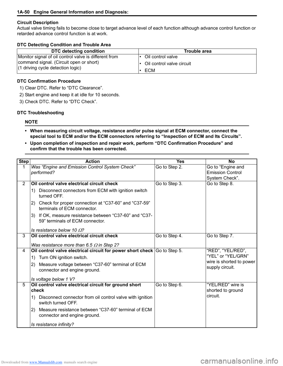
Circuit Description
Actual valve timing fails to become close to target advance level of each function although advance control function or
retarded advance control function is at work.
DTC Detecting Condition and Trouble Area
DTC Confirmation Procedure 1) Clear DTC. Refer to “DTC Clearance”.
2) Start engine and keep it at idle for 10 seconds.
3) Check DTC. Refer to “DTC Check”.
DTC Troubleshooting
NOTE
• When measuring circuit voltage, resistance and/ or pulse signal at ECM connector, connect the
special tool to ECM and/or the ECM connectors re ferring to “Inspection of ECM and Its Circuits”.
• Upon completion of inspection and repair work, perform “DTC Confirmation Procedure” and confirm that the trouble has been corrected.
DTC detecting condition Trouble area
Monitor signal of oil control valve is different from
command signal. (Circuit open or short)
(1 driving cycle detection logic) • Oil control valve
• Oil control valve circuit
•ECM
Step
Action YesNo
1 Was “Engine and Emission Control System Check”
performed? Go to Step 2.
Go to “Engine and
Emission Control
System Check”.
2 Oil control valve electrical circuit check
1) Disconnect connectors from ECM with ignition switch
turned OFF.
2) Check for proper connection at “C37-60” and “C37-59” terminals of ECM connector.
3) If OK, measure resistance between “C37-60” and “C37- 59” terminals of ECM connector.
Is resistance below 10
Ω? Go to Step 3. Go to Step 8.
3 Oil control valve electrical circuit check
Was resistance more than 6.5
Ω in Step 2? Go to Step 4. Go to Step 7.
4 Oil control valve electrical circuit for power short check
1) Turn ON ignition switch.
2) Measure voltage between “C37-60” terminal of ECM
connector and engine ground.
Is voltage below 1 V? Go to Step 5. “RED”, “YEL/RED”,
“YEL” or “YEL/GRN”
wire is shorted to power
supply circuit.
5 Oil control valve electrical circuit for ground short
check
1) Disconnect connector from oil control valve with ignition
switch turned OFF.
2) Measure resistance between “C37-60” terminal of ECM connector and engine ground.
Is resistance infinity? Go to Step 6. “YEL/RED” wire is
shorted to ground
circuit.
Page 101 of 1496
Downloaded from www.Manualslib.com manuals search engine Engine General Information and Diagnosis: 1A-51
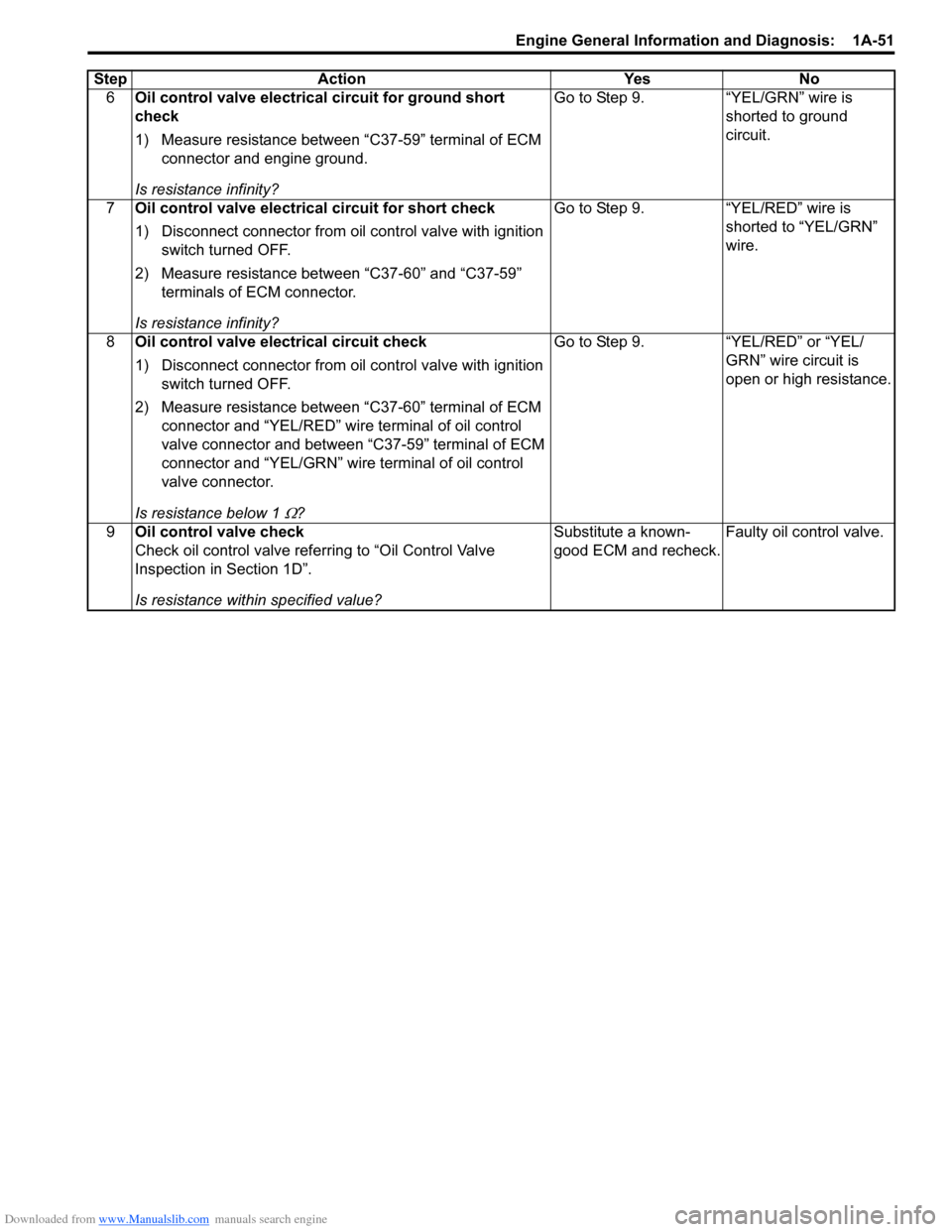
6Oil control valve electrical circuit for ground short
check
1) Measure resistance between “C37-59” terminal of ECM
connector and engine ground.
Is resistance infinity? Go to Step 9.
“YEL/GRN” wire is
shorted to ground
circuit.
7 Oil control valve electrical circuit for short check
1) Disconnect connector from oil control valve with ignition
switch turned OFF.
2) Measure resistance between “C37-60” and “C37-59” terminals of ECM connector.
Is resistance infinity? Go to Step 9.
“YEL/RED” wire is
shorted to “YEL/GRN”
wire.
8 Oil control valve electrical circuit check
1) Disconnect connector from oil control valve with ignition
switch turned OFF.
2) Measure resistance between “C37-60” terminal of ECM connector and “YEL/RED” wire terminal of oil control
valve connector and between “C37-59” terminal of ECM
connector and “YEL/GRN” wir e terminal of oil control
valve connector.
Is resistance below 1
Ω? Go to Step 9. “YEL/RED” or “YEL/
GRN” wire circuit is
open or high resistance.
9 Oil control valve check
Check oil control valve refe rring to “Oil Control Valve
Inspection in Section 1D”.
Is resistance within specified value? Substitute a known-
good ECM and recheck.
Faulty oil control valve.
Step Action Yes No
Page 102 of 1496
Downloaded from www.Manualslib.com manuals search engine 1A-52 Engine General Information and Diagnosis:
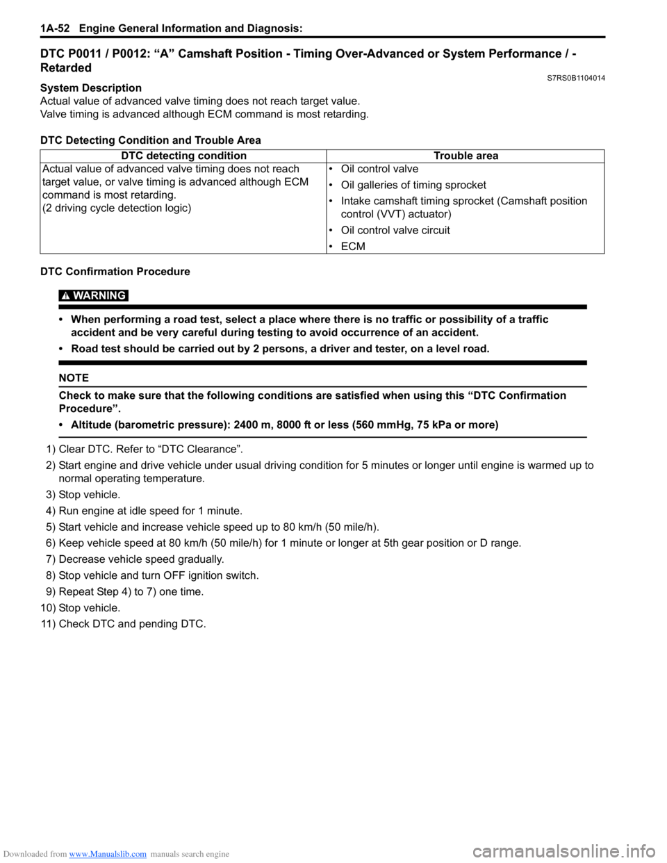
DTC P0011 / P0012: “A” Camshaft Position - Timing Over-Advanced or System Performance / -
Retarded
S7RS0B1104014
System Description
Actual value of advanced valve timing does not reach target value.
Valve timing is advanced although ECM command is most retarding.
DTC Detecting Condition and Trouble Area
DTC Confirmation Procedure
WARNING!
• When performing a road test, select a place where there is no traffic or possibility of a traffic accident and be very careful during testing to avoid occurrence of an accident.
• Road test should be carried out by 2 persons, a driver and tester, on a level road.
NOTE
Check to make sure that the following conditions are satisfied when using this “DTC Confirmation
Procedure”.
• Altitude (barometric pressure): 2400 m, 8000 ft or less (560 mmHg, 75 kPa or more)
1) Clear DTC. Refer to “DTC Clearance”.
2) Start engine and drive vehicle under usual driving condition for 5 minutes or longer until engine is warmed up to normal operating temperature.
3) Stop vehicle.
4) Run engine at idle speed for 1 minute.
5) Start vehicle and increase vehicle speed up to 80 km/h (50 mile/h).
6) Keep vehicle speed at 80 km/h (50 mile/h) for 1 minute or longer at 5th gear position or D range.
7) Decrease vehicle speed gradually.
8) Stop vehicle and turn OFF ignition switch.
9) Repeat Step 4) to 7) one time.
10) Stop vehicle. 11) Check DTC and pending DTC. DTC detecting condition
Trouble area
Actual value of advanced valve timing does not reach
target value, or valve timi ng is advanced although ECM
command is most retarding.
(2 driving cycle detection logic) • Oil control valve
• Oil galleries of timing sprocket
• Intake camshaft timing sprocket (Camshaft position
control (VVT) actuator)
• Oil control valve circuit
•ECM
Page 103 of 1496
Downloaded from www.Manualslib.com manuals search engine Engine General Information and Diagnosis: 1A-53
DTC Troubleshooting
NOTE
• When measuring circuit voltage, resistance and/or pulse signal at ECM connector, connect the
special tool to ECM and/or the ECM connectors re ferring to “Inspection of ECM and Its Circuits”.
• Upon completion of inspection and repair work, perform “DTC Confirmation Procedure” and confirm that the trouble has been corrected.
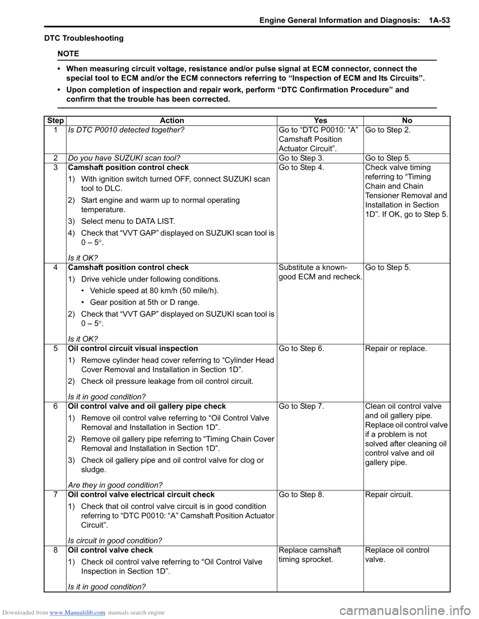
Step Action YesNo
1 Is DTC P0010 detected together? Go to “DTC P0010: “A”
Camshaft Position
Actuator Circuit”.Go to Step 2.
2 Do you have SUZUKI scan tool? Go to Step 3.Go to Step 5.
3 Camshaft position control check
1) With ignition switch turned OFF, connect SUZUKI scan
tool to DLC.
2) Start engine and warm up to normal operating temperature.
3) Select menu to DATA LIST.
4) Check that “VVT GAP” displayed on SUZUKI scan tool is 0 – 5 °.
Is it OK? Go to Step 4.
Check valve timing
referring to “Timing
Chain and Chain
Tensioner Removal and
Installation in Section
1D”. If OK, go to Step 5.
4 Camshaft position control check
1) Drive vehicle under following conditions.
• Vehicle speed at 80 km/h (50 mile/h).
• Gear position at 5th or D range.
2) Check that “VVT GAP” displayed on SUZUKI scan tool is 0 – 5 °.
Is it OK? Substitute a known-
good ECM and recheck.
Go to Step 5.
5 Oil control circuit visual inspection
1) Remove cylinder head cover referring to “Cylinder Head
Cover Removal and Insta llation in Section 1D”.
2) Check oil pressure leakage from oil control circuit.
Is it in good condition? Go to Step 6.
Repair or replace.
6 Oil control valve and oil gallery pipe check
1) Remove oil control valve re ferring to “Oil Control Valve
Removal and Installation in Section 1D”.
2) Remove oil gallery pipe refe rring to “Timing Chain Cover
Removal and Installation in Section 1D”.
3) Check oil gallery pipe and o il control valve for clog or
sludge.
Are they in good condition? Go to Step 7.
Clean oil control valve
and oil gallery pipe.
Replace oil control valve
if a problem is not
solved after cleaning oil
control valve and oil
gallery pipe.
7 Oil control valve electrical circuit check
1) Check that oil control valve circuit is in good condition
referring to “DTC P0010: “A” Camshaft Position Actuator
Circuit”.
Is circuit in good condition? Go to Step 8.
Repair circuit.
8 Oil control valve check
1) Check oil control valve refe rring to “Oil Control Valve
Inspection in Section 1D”.
Is it in good condition? Replace camshaft
timing sprocket.
Replace oil control
valve.
Page 169 of 1496
Downloaded from www.Manualslib.com manuals search engine Engine General Information and Diagnosis: 1A-119
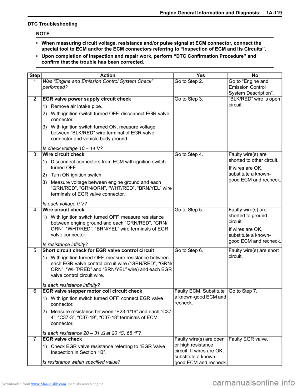
DTC Troubleshooting
NOTE
• When measuring circuit voltage, resistance and/or pulse signal at ECM connector, connect the
special tool to ECM and/or the ECM connectors re ferring to “Inspection of ECM and Its Circuits”.
• Upon completion of inspection and repair work, perform “DTC Confirmation Procedure” and confirm that the trouble has been corrected.
Step Action YesNo
1 Was “Engine and Emission Control System Check”
performed? Go to Step 2.
Go to “Engine and
Emission Control
System Description”.
2 EGR valve power supply circuit check
1) Remove air intake pipe.
2) With ignition switch turned OFF, disconnect EGR valve
connector.
3) With ignition switch turned ON, measure voltage between “BLK/RED” wire terminal of EGR valve
connector and vehicle body ground.
Is check voltage 10 – 14 V? Go to Step 3.
“BLK/RED” wire is open
circuit.
3 Wire circuit check
1) Disconnect connectors from ECM with ignition switch
turned OFF.
2) Turn ON ignition switch.
3) Measure voltage between engine ground and each “GRN/RED”, “GRN/ORN”, “W HT/RED”, “BRN/YEL” wire
terminals of EGR valve connector.
Is each voltage 0 V? Go to Step 4.
Faulty wire(s) are
shorted to other circuit.
If wires are OK,
substitute a known-
good ECM and recheck.
4 Wire circuit check
1) With ignition switch turned OFF, measure resistance
between engine ground and each “GRN/RED”, “GRN/
ORN”, “WHT/RED”, “BRN/YEL” wire terminals of EGR
valve connector.
Is resistance infinity? Go to Step 5.
Faulty wire(s) are
shorted to ground
circuit.
If wires are OK,
substitute a known-
good ECM and recheck.
5 Short circuit check for EGR valve control circuit
1) With ignition turned OFF, measure resistance between
each EGR valve control circ uit wire (“GRN/RED”, “GRN/
ORN”, “WHT/RED” and “BRN/ YEL” wire) and each EGR
valve control circuit wire.
Is each resistance infinity? Go to Step 6.
Faulty wire(s) are short
circuit.
6 EGR valve stepper motor coil circuit check
1) With ignition switch turned OFF, connect EGR valve
connector.
2) Measure resistance between “E23-1/16” and each “C37- 4”, “C37-3”, “C37-19”, “C37-18” terminals of ECM
connector.
Is each resistance 20 – 31
Ω at 20 °C, 68 °F? Faulty ECM. Substitute
a known-good ECM and
recheck.
Go to Step 7.
7 EGR valve check
1) Check EGR valve resistance referring to “EGR Valve
Inspection in Section 1B”.
Is resistance within specified value? Faulty wire(s) are open
or high resistance
circuit. If wires are OK,
substitute a known-
good ECM and recheck.Faulty EGR valve.
Page 172 of 1496
Downloaded from www.Manualslib.com manuals search engine 1A-122 Engine General Information and Diagnosis:
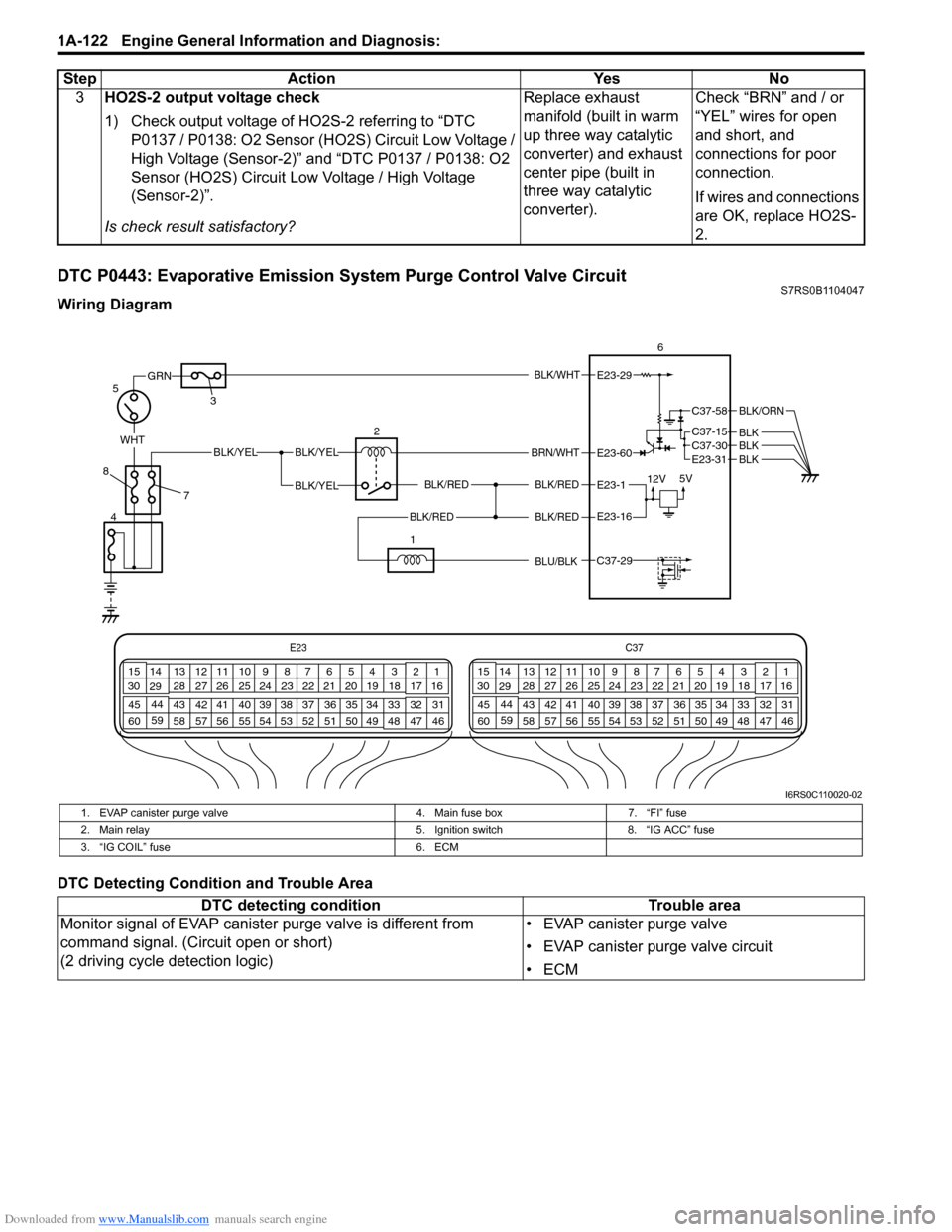
DTC P0443: Evaporative Emission System Purge Control Valve CircuitS7RS0B1104047
Wiring Diagram
DTC Detecting Condition and Trouble Area3
HO2S-2 output voltage check
1) Check output voltage of HO2S-2 referring to “DTC
P0137 / P0138: O2 Sensor (HO2S) Circuit Low Voltage /
High Voltage (Sensor-2)” and “DTC P0137 / P0138: O2
Sensor (HO2S) Circuit Low Voltage / High Voltage
(Sensor-2)”.
Is check result satisfactory? Replace exhaust
manifold (built in warm
up three way catalytic
converter) and exhaust
center pipe (built in
three way catalytic
converter).
Check “BRN” and / or
“YEL” wires for open
and short, and
connections for poor
connection.
If wires and connections
are OK, replace HO2S-
2.
Step Action Yes No
E23
C37
34
1819
567
1011
17
20
47 46
495051
2122
52 16
25 9
24
14
29
55
57 54 53
59
60 58 2
262728
15
30
56 4832 31
34353637
40
42 39 38
44
45 43 41 33 1
1213
238
34
1819
567
1011
17
20
47 46
495051
2122
52 16
25 9
24
14
29
55
57 54 53
59
60 58 2
262728
15
30
56 48 32 31
34353637
40
42 39 38
44
45 43 41 331
1213
238
BLK/WHT
BLK/RED
BLK/RED
WHTBLK/YELBLK/YEL
BLK/YEL
GRN
BRN/WHT
12V 5V
5
4 2
3 6E23-29
E23-1
E23-60
C37-58
C37-15 C37-30
BLK/ORN
BLKBLKE23-31 BLK
7
8
BLK/REDBLK/REDE23-16
1
C37-29 BLU/BLK
I6RS0C110020-02
1. EVAP canister purge valve
4. Main fuse box7. “FI” fuse
2. Main relay 5. Ignition switch8. “IG ACC” fuse
3. “IG COIL” fuse 6. ECM
DTC detecting conditionTrouble area
Monitor signal of EVAP canister purge valve is different from
command signal. (Circuit open or short)
(2 driving cycle detection logic) • EVAP canister purge valve
• EVAP canister purge valve circuit
•ECM
Page 230 of 1496
Downloaded from www.Manualslib.com manuals search engine 1A-180 Engine General Information and Diagnosis:
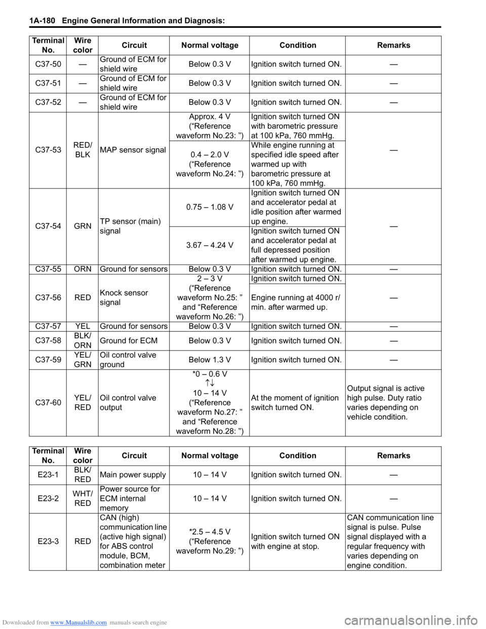
C37-50 —Ground of ECM for
shield wire Below 0.3 V Ignition switch turned ON. —
C37-51 — Ground of ECM for
shield wire Below 0.3 V Ignition switch turned ON. —
C37-52 — Ground of ECM for
shield wire Below 0.3 V Ignition switch turned ON. —
C37-53 RED/
BLK MAP sensor signal Approx. 4 V
(“Reference
waveform No.23: ”) Ignition switch turned ON
with barometric pressure
at 100 kPa, 760 mmHg.
—
0.4 – 2.0 V
(“Reference
waveform No.24: ”) While engine running at
specified idle speed after
warmed up with
barometric pressure at
100 kPa, 760 mmHg.
C37-54 GRN TP sensor (main)
signal 0.75 – 1.08 V
Ignition switch turned ON
and accelerator pedal at
idle position after warmed
up engine.
—
3.67 – 4.24 V Ignition switch turned ON
and accelerator pedal at
full depressed position
after warmed up engine.
C37-55 ORN Ground for sensors Below 0.3 V Ignition switch turned ON. —
C37-56 RED Knock sensor
signal 2 – 3 V
(“Reference
waveform No.25: ” and “Reference
waveform No.26: ”) Ignition switch turned ON.
—
Engine running at 4000 r/
min. after warmed up.
C37-57 YEL Ground for sensors Below 0.3 V Ignition switch turned ON. —
C37-58 BLK/
ORN Ground for ECM Below 0.3 V Ignition switch turned ON.
—
C37-59 YEL/
GRN Oil control valve
ground
Below 1.3 V Ignition switch turned ON.
—
C37-60 YEL/
RED Oil control valve
output *0 – 0.6 V
↑↓
10 – 14 V
(“Reference
waveform No.27: ” and “Reference
waveform No.28: ”) At the moment of ignition
switch turned ON.
Output signal is active
high pulse. Duty ratio
varies depending on
vehicle condition.
Terminal
No. Wire
color Circuit Normal voltage
ConditionRemarks
Terminal
No. Wire
color Circuit Normal voltage Condition Remarks
E23-1 BLK/
RED Main power supply 10 – 14 V Ignition switch turned ON. —
E23-2 WHT/
RED Power source for
ECM internal
memory
10 – 14 V Ignition switch turned ON. —
E23-3 RED CAN (high)
communication line
(active high signal)
for ABS control
module, BCM,
combination meter *2.5 – 4.5 V
(“Reference
waveform No.29: ”) Ignition switch turned ON
with engine at stop. CAN communication line
signal is pulse. Pulse
signal displayed with a
regular frequency with
varies depending on
engine condition.
Page 241 of 1496
Downloaded from www.Manualslib.com manuals search engine Engine General Information and Diagnosis: 1A-191
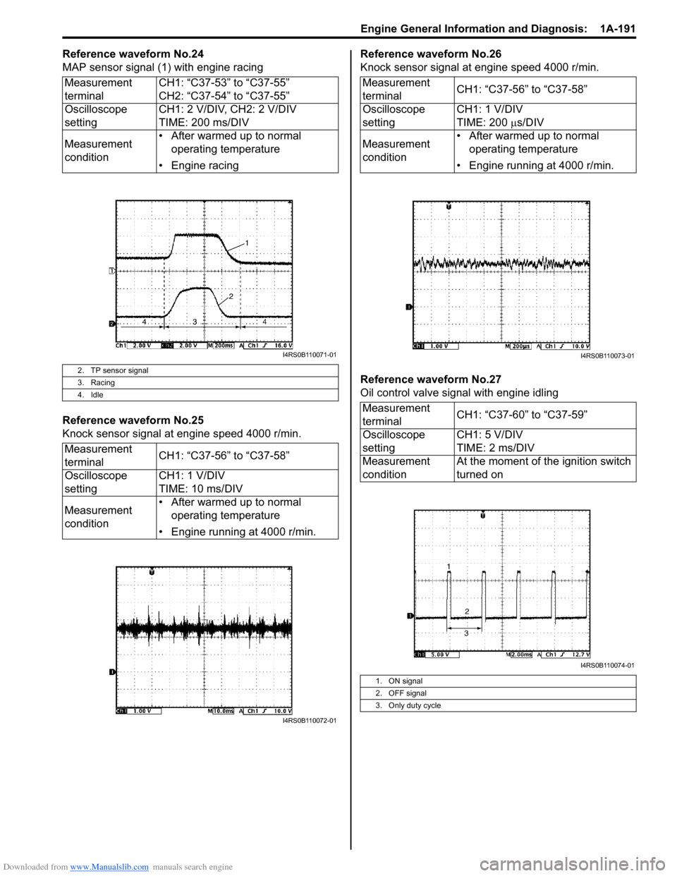
Reference waveform No.24
MAP sensor signal (1) with engine racing
Reference waveform No.25
Knock sensor signal at engine speed 4000 r/min.Reference waveform No.26
Knock sensor signal at engine speed 4000 r/min.
Reference waveform No.27
Oil control valve signal with engine idling
Measurement
terminal
CH1: “C37-53” to “C37-55”
CH2: “C37-54” to “C37-55”
Oscilloscope
setting CH1: 2 V/DIV, CH2: 2 V/DIV
TIME: 200 ms/DIV
Measurement
condition • After warmed up to normal
operating temperature
• Engine racing
2. TP sensor signal
3. Racing
4. Idle
Measurement
terminal CH1: “C37-56” to “C37-58”
Oscilloscope
setting CH1: 1 V/DIV
TIME: 10 ms/DIV
Measurement
condition • After warmed up to normal
operating temperature
• Engine running at 4000 r/min.
I4RS0B110071-01
I4RS0B110072-01
Measurement
terminal CH1: “C37-56” to “C37-58”
Oscilloscope
setting CH1: 1 V/DIV
TIME: 200
µs/DIV
Measurement
condition • After warmed up to normal
operating temperature
• Engine running at 4000 r/min.
Measurement
terminal CH1: “C37-60” to “C37-59”
Oscilloscope
setting CH1: 5 V/DIV
TIME: 2 ms/DIV
Measurement
condition At the moment of the ignition switch
turned on
1. ON signal
2. OFF signal
3. Only duty cycle
I4RS0B110073-01
I4RS0B110074-01