2007 SUZUKI SWIFT Engine mount bracket
[x] Cancel search: Engine mount bracketPage 643 of 1496
Downloaded from www.Manualslib.com manuals search engine Table of Contents 5-iii
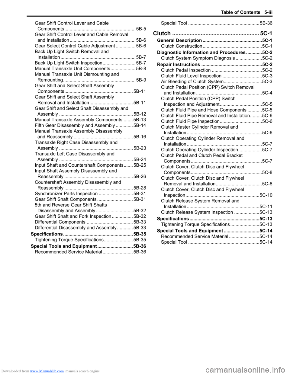
Gear Shift Control Lever and Cable Components...................................................... 5B-5
Gear Shift Control Le ver and Cable Removal
and Installation .................................................. 5B-6
Gear Select Control Cable Adjustment ............... 5B-6
Back Up Light Switch Removal and Installation ......................................................... 5B-7
Back Up Light Switch Inspection ......................... 5B-7
Manual Transaxle Unit Components ................... 5B-8
Manual Transaxle Unit Dismounting and Remounting....................................................... 5B-9
Gear Shift and Sele ct Shaft Assembly
Components.................................................... 5B-11
Gear Shift and Sele ct Shaft Assembly
Removal and Installation................................. 5B-11
Gear Shift and Select Shaft Disassembly and Assembly ........................................................ 5B-12
Manual Transaxle Assembly Components........ 5B-13
Fifth Gear Disassembly and Assembly ............. 5B-14
Manual Transaxle Assembly Disassembly and Reassembly ............................................. 5B-16
Transaxle Right Case Disassembly and Assembly ........................................................ 5B-23
Transaxle Left Case Disassembly and Assembly ........................................................ 5B-24
Input Shaft and Countershaft Components....... 5B-25
Input Shaft Assembly Disassembly and Reassembly .................................................... 5B-26
Countershaft Assembly Disassembly and Reassembly .................................................... 5B-28
Synchronizer Parts Inspec tion .......................... 5B-31
Gear Shift Shaft Components ........................... 5B-31
5th and Reverse Gear Shift Shafts Disassembly and Assembly ............................ 5B-32
Gear Shift Shaft and Fork Inspection ................ 5B-32
Differential Components ................................... 5B-33
Differential Disassembly and Assembly ............ 5B-33
Specifications ..................................................... 5B-35
Tightening Torque Specifications ...................... 5B-35
Special Tools and Equipmen t ........................... 5B-36
Recommended Service Material ....................... 5B-36 Special Tool ...................................................... 5B-36
Clutch ................
.............................. ......... 5C-1
General Description .............................................5C-1
Clutch Construction .............................................5C-1
Diagnostic Information and Procedures ............5C-2 Clutch System Symptom Diagnosis ....................5C-2
Repair Instructions ........... ...................................5C-2
Clutch Pedal Inspection ......................................5C-2
Clutch Fluid Level Inspection ..............................5C-3
Air Bleeding of Clutch System.............................5C-3
Clutch Pedal Position (CPP) Switch Removal and Installation ..................................................5C-4
Clutch Pedal Position (CPP) Switch Inspection and Adjustment ................................5C-5
Clutch Fluid Pipe and Hose Components ...........5C-5
Clutch Fluid Pipe Removal and Installation.........5C-6
Clutch Fluid Pipe Inspection................................5C-6
Clutch Master Cylinder Removal and Installation .........................................................5C-6
Clutch Operating Cylinder Removal and Installation .........................................................5C-7
Clutch Operating Cylinder Inspection..................5C-7
Clutch Pedal and Clutch Pedal Bracket Components ......................................................5C-7
Clutch Cover, Clutch Disc and Flywheel Components ......................................................5C-8
Clutch Cover, Clutch Disc and Flywheel Removal and Installation ...................................5C-8
Clutch Cover, Clutch Disc and Flywheel Inspection ........................................................5C-10
Clutch Release Syst em Removal and
Installation .......................................................5C-11
Clutch Release System Inspection ...................5C-13
Specifications .................... .................................5C-13
Tightening Torque Specifications ......................5C-13
Special Tools and Equipmen t ...........................5C-14
Recommended Service Material .......................5C-14
Special Tool ......................................................5C-14
Page 754 of 1496
Downloaded from www.Manualslib.com manuals search engine 5A-110 Automatic Transmission/Transaxle:
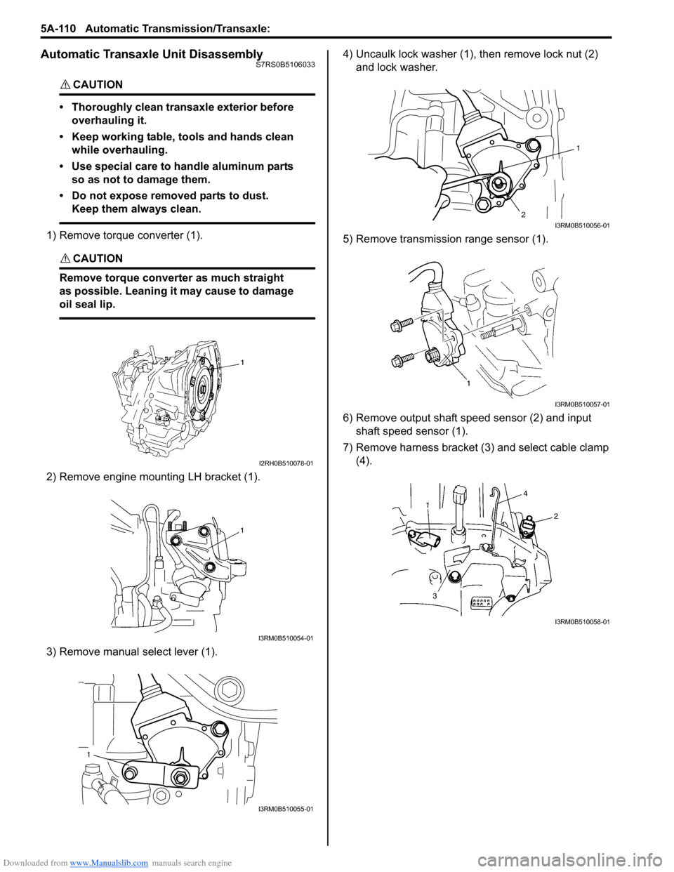
Automatic Transaxle Unit DisassemblyS7RS0B5106033
CAUTION!
• Thoroughly clean transaxle exterior before overhauling it.
• Keep working table, tools and hands clean while overhauling.
• Use special care to handle aluminum parts so as not to damage them.
• Do not expose removed parts to dust. Keep them always clean.
1) Remove torque converter (1).
CAUTION!
Remove torque converte r as much straight
as possible. Leaning it may cause to damage
oil seal lip.
2) Remove engine mounting LH bracket (1).
3) Remove manual select lever (1). 4) Uncaulk lock washer (1),
then remove lock nut (2)
and lock washer.
5) Remove transmission range sensor (1).
6) Remove output shaft speed sensor (2) and input shaft speed sensor (1).
7) Remove harness bracket (3) and select cable clamp (4).
I2RH0B510078-01
I3RM0B510054-01
1
I3RM0B510055-01
1
2
I3RM0B510056-01
I3RM0B510057-01
I3RM0B510058-01
Page 810 of 1496
Downloaded from www.Manualslib.com manuals search engine 5A-166 Automatic Transmission/Transaxle:
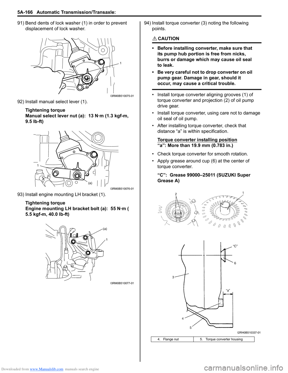
91) Bend dents of lock washer (1) in order to prevent displacement of lock washer.
92) Install manual select lever (1). Tightening torque
Manual select lever nut (a): 13 N·m (1.3 kgf-m,
9.5 lb-ft)
93) Install engine mounting LH bracket (1). Tightening torque
Engine mounting LH bracket bolt (a): 55 N·m (
5.5 kgf-m, 40.0 lb-ft) 94) Install torque converter (3) noting the following
points.
CAUTION!
• Before installing converter, make sure that its pump hub portion is free from nicks,
burrs or damage which may cause oil seal
to leak.
• Be very careful not to drop converter on oil pump gear. Damage in gear, should it
occur, may cause a critical trouble.
• Install torque converter aligning grooves (1) of torque converter and projection (2) of oil pump
drive gear.
• Install torque converter, using care not to damage oil seal of oil pump.
• After installing torque converter, check that distance “a” is within specification.
Torque converter installing position
“a”: More than 19.9 mm (0.783 in.)
• Check torque converter for smooth rotation.
• Apply grease around cup (6) at the center of torque converter.
“C”: Grease 99000–25011 (SUZUKI Super
Grease A)
1
I3RM0B510075-01
1
(a)
I3RM0B510076-01
I3RM0B510077-01
4. Flange nut 5. Torque converter housing
I2RH0B510337-01
Page 811 of 1496
Downloaded from www.Manualslib.com manuals search engine Automatic Transmission/Transaxle: 5A-167
Specifications
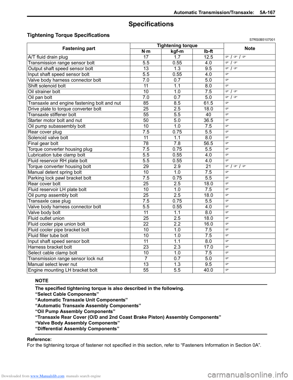
Tightening Torque SpecificationsS7RS0B5107001
NOTE
The specified tightening torque is also described in the following.
“Select Cable Components”
“Automatic Transaxle Unit Components”
“Automatic Transaxle Assembly Components”
“Oil Pump Assembly Components”
“Transaxle Rear Cover (O/D and 2nd Coast Brake Piston) Assembly Components”
“Valve Body Assembly Components”
“Differential Assembly Components”
Reference:
For the tightening torque of fastener not specified in this section, refer to “Fasteners Information in Section 0A”.
Fastening part
Tightening torque
Note
N ⋅mkgf-mlb-ft
A/T fluid drain plug 171.7 12.5 ) / ) / )
Transmission range sensor bolt 5.5 0.55 4.0) / )
Output shaft speed sensor bolt 131.3 9.5 ) / )
Input shaft speed sensor bolt 5.5 0.55 4.0)
Valve body harness connector bolt 7.00.7 5.0 )
Shift solenoid bolt 111.1 8.0 )
Oil strainer bolt 101.0 7.5 ) / )
Oil pan bolt 7.00.7 5.0 ) / )
Transaxle and engine fastening bolt and nut 85 8.5 61.5)
Drive plate to torque converter bolt 252.5 18.0 )
Transaxle stiffener bolt 555.5 40)
Starter motor bolt and nut 505.0 36.5 )
Oil pump subassembly bolt 101.0 7.5 )
Rear cover plug 7.5 0.75 5.5)
Solenoid valve bolt 111.1 8.0 )
Final gear bolt 787.8 56.5 )
Torque converter housing plug 7.5 0.75 5.5)
Lubrication tube clamp bolt 5.5 0.55 4.0)
Fluid reservoir RH plate bolt 5.5 0.55 4.0)
Torque converter housing bolt 292.9 21) / ) / )
Manual detent spring bolt 101.0 7.5 )
Parking lock pawl bracket bolt 7.5 0.75 5.5)
Rear cover bolt 252.5 18.0 )
Fluid reservoir LH plate bolt 101.0 7.5 )
Oil pump assembly bolt 252.5 18.0 )
Transaxle case plug 7.5 0.75 5.5)
Valve body harness connector bolt 5.5 0.55 4.0)
Valve body bolt 111.1 8.0 )
Fluid outlet union 252.5 18.0 )
Fluid cooler pipe union bolt 222.2 16.0 )
Fluid cooler pipe bracket bolt 101.0 7.5 )
Fluid filler tube bolt 101.0 7.5 )
Input shaft speed sensor bolt 111.1 8.0 )
Harness bracket bolt 232.3 17.0 )
Select cable clamp bolt 101.0 7.5 )
Transmission range sensor lock nut 70.7 5.0 )
Manual select lever nut 131.3 9.5 )
Engine mounting LH bracket bolt 555.5 40.0
)
Page 819 of 1496

Downloaded from www.Manualslib.com manuals search engine Manual Transmission/Transaxle: 5B-5
Gear Shift Control Lever and Cable ComponentsS7RS0B5206003
1
3
4
(a)
7
A
(b)5
A
111 2
10
(c)
9
6
8 2
I7RS0A521001-03
1. Gear shift control lever knob 9. Cable bracket
2. Cable bracket bolt 10. Clip
Be sure to direct claw of clip to M/T side as shown in figure.
3. Gear shift lever boot 11. To gear shift control lever assembly
4. Gear shift control cable : Apply grease 99000-25011 to cable end. 12. To M/T
5. Gear select control cable : Apply grease 99000-25011 to cable end. : 13 N
⋅m (1.3 kgf-m, 9.5 lb-ft)
6. Gear shift control lever assembly mounting nut : 10 N⋅m (1.0 kgf-m, 7.5 lb-ft)
7. Gear shift control lever assembly : 55 N⋅m (5.5 kgf-m, 40.0 lb-ft)
8. Cable grommet bolt : Do not reuse.
Page 822 of 1496
![SUZUKI SWIFT 2007 2.G Service Workshop Manual Downloaded from www.Manualslib.com manuals search engine 5B-8 Manual Transmission/Transaxle:
Manual Transaxle Unit ComponentsS7RS0B5206008
13
6(a)
5
14(c)
114 7
(b)
12
7(b)
8
2
5 [A]
1
10
6
(a)
(a)
(](/manual-img/20/7607/w960_7607-821.png "SUZUKI SWIFT 2007 2.G Service Workshop Manual Downloaded from www.Manualslib.com manuals search engine 5B-8 Manual Transmission/Transaxle:
Manual Transaxle Unit ComponentsS7RS0B5206008
13
6(a)
5
14(c)
114 7
(b)
12
7(b)
8
2
5 [A]
1
10
6
(a)
(a)
(")
Downloaded from www.Manualslib.com manuals search engine 5B-8 Manual Transmission/Transaxle:
Manual Transaxle Unit ComponentsS7RS0B5206008
13
6(a)
5
14(c)
114 7
(b)
12
7(b)
8
2
5 [A]
1
10
6
(a)
(a)
(b)3
9
9
(b)
(d)
I6RS0C520004-03
[A]: Forward
7. Engine left mounting bracket bolt and nuts 14. Clutch operating cylinder bolt
1. Engine 8. Clutch housing lower plate : 85 N⋅m (8.5 kgf-m, 61.5 lb-ft)
2. Transaxle 9. Engine rear mounting bracket bolts : 55 N⋅m (5.5 kgf-m, 40.0 lb-ft)
3. Engine rear mounting and bracket 10. Transaxle to engine nut : 23 N⋅m (2.3 kgf-m, 17.0 lb-ft)
4. Back up light switch connector 11. Ground cable : 11 N⋅m (1.1 kgf-m, 8.0 lb-ft)
5. Clutch operating cylinder 12. Engine left mounting bracket
6. Transaxle to engine bolt 13. Gear shift & select control cables
Page 824 of 1496

Downloaded from www.Manualslib.com manuals search engine 5B-10 Manual Transmission/Transaxle:
16) Remove engine under covers.
17) Support transaxle with transmission jack.
18) Remove transaxle to engine bolts and nut of lower side.
19) Remove engine left mounting (1) with bracket (2).
20) Remove engine rear mounting bracket bolts (1).
21) Remove other attached parts from transaxle, if any.
22) Pull transaxle so as to disconnect input shaft from clutch disc, and then lower it. Remounting
CAUTION!
• Care should be taken not to scratch oil
seal lip with drive shaft while raising
transaxle.
• Do not hit drive shaft joint with hammer when installing it into differential gear.
Reverse dismounting procedure for remounting noting
the following.
• Tighten each bolts and nuts to specified torque referring to “Manual Transaxle Unit Components”.
• Set each clamp for wiring securely.
• Fill transaxle oil referring to “Manual Transaxle Oil
Change”.
• Fill coolant referring to “Cooling System Flush and
Refill in Section 1F”.
• Install hook (1) and ground cable (2) at specified position as shown in figure.
• Connect battery and check function of engine, clutch
and transaxle.
1
2
I4RS0A520021-01
1
I4RS0A520022-01
3. Transaxle side cover 4. Transaxle left case
90
1
2 3
4
I4RS0A520023-01
Page 879 of 1496
Downloaded from www.Manualslib.com manuals search engine Steering Wheel and Column: 6B-8
Installation
CAUTION!
After tightening steering column mounting
nuts, shaft joint bolts should be tightened.
Wrong tightening order could cause a
damage to shaft joint.
1) Be sure that front wheels are in straight.
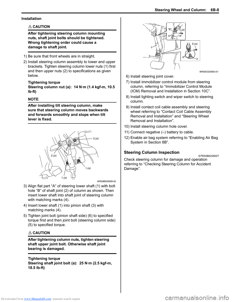
2) Install steering column assembly to lower and upper brackets. Tighten steering column lower nuts (1) first
and then upper nuts (2) to specifications as given
below.
Tightening torque
Steering column nut (a): 14 N·m (1.4 kgf-m, 10.5
lb-ft)
NOTE
After installing tilt steering column, make
sure that steering column moves backwards
and forwards smoothly and stops when tilt
lever is fixed.
3) Align flat part “A” of stee ring lower shaft (1) with bolt
hole “B” of shaft joint (2) of column as shown. Then
insert lower shaft into shaf t joint of steering column
with matching marks (4).
4) Insert lower shaft (1) into pinion shaft (3) with matching marks (4).
5) Tighten joint bolt (pinion shaft side) (6) to specified torque first and then joint bolt (steering column side)
(5) to specified torque.
CAUTION!
After tightening column nuts, tighten steering
shaft upper joint bolt. Otherwise shaft joint
bearing is damaged.
Tightening torque
Steering shaft joint bolt (a): 25 N·m (2.5 kgf-m,
18.5 lb-ft) 6) Install steering joint cover.
7) Install immobilizer cont
rol module from steering
column, referring to “Immo bilizer Control Module
(ICM) Removal and Installation in Section 10C”.
8) Install lighting switch and wiper switch to steering column.
9) Install contact coil cable assembly and steering wheel referring to “Conta ct Coil Cable Assembly
Removal and Installation” and “Steering Wheel
Removal and Installation”.
10) Install steering column hole cover. 11) Connect negative (–) battery to cable.
12) Enable air bag system refe rring to “Enabling Air Bag
System in Section 8B”.
Steering Column InspectionS7RS0B6206007
Check steering column for damage and operation
referring to “Checking Steering Column for Accident
Damage”.
2,(a)
1,(a)
1,(a)
2,(a)
I4RS0B620009-02
I6RS0C620003-01