2007 SUZUKI SWIFT Engine mount bracket
[x] Cancel search: Engine mount bracketPage 304 of 1496
Downloaded from www.Manualslib.com manuals search engine 1D-19 Engine Mechanical:
24) Before removing engine with transaxle from engine compartment, recheck to make sure all hoses,
electric wires and cables are disconnected from
engine and transaxle.
25) Lower engine with transaxle from engine compartment.
CAUTION!
Before lowering engine, to avoid damage to
A/C compressor and clutch operating
cylinder, make clearance by rising them. Be
sure not to damage suspended A/C
compressor and clutch operating cylinder.
26) Disconnect transaxle from engine, referring to “Manual Transaxle Unit Dismounting and
Remounting in Section 5B” or “Automatic Transaxle
Unit Dismounting and Re mounting in Section 5A”.
27) For M/T model, remove clutch cover and clutch disk referring to “Clutch Cover, Clutch Disc and Flywheel
Removal and Installa tion in Section 5C”.
Installation 1) For M/T model, install clutch cover and clutch disk referring to “Clutch Cover, Clutch Disc and Flywheel
Removal and Installa tion in Section 5C”.
2) Connect transaxle to engine referring to “Manual Transaxle Unit Dismounting and Remounting in
Section 5B” or “Automatic Transaxle Unit
Dismounting and Remounting in Section 5A”.
3) Lift engine and transaxle into engine compartment with jack.
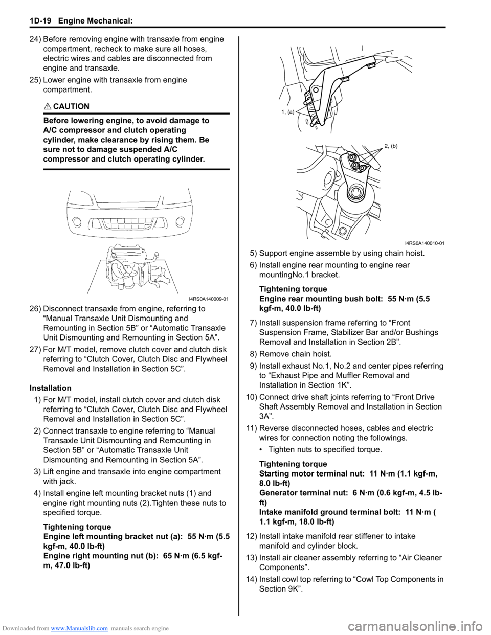
4) Install engine left mounting bracket nuts (1) and engine right mounting nuts (2).Tighten these nuts to
specified torque.
Tightening torque
Engine left mounting bracket nut (a): 55 N·m (5.5
kgf-m, 40.0 lb-ft)
Engine right mounting nut (b): 65 N·m (6.5 kgf-
m, 47.0 lb-ft) 5) Support engine assemble by using chain hoist.
6) Install engine rear mounting to engine rear
mountingNo.1 bracket.
Tightening torque
Engine rear mounting bush bolt: 55 N·m (5.5
kgf-m, 40.0 lb-ft)
7) Install suspension frame referring to “Front Suspension Frame, Stabiliz er Bar and/or Bushings
Removal and Installati on in Section 2B”.
8) Remove chain hoist.
9) Install exhaust No.1, No.2 and center pipes referring to “Exhaust Pipe and Muffler Removal and
Installation in Section 1K”.
10) Connect drive shaft joints referring to “Front Drive Shaft Assembly Removal and Installation in Section
3A”.
11) Reverse disconnected hoses, cables and electric wires for connection noting the followings.
• Tighten nuts to specified torque.
Tightening torque
Starting motor terminal nut: 11 N·m (1.1 kgf-m,
8.0 lb-ft)
Generator terminal nut: 6 N·m (0.6 kgf-m, 4.5 lb-
ft)
Intake manifold ground terminal bolt: 11 N·m (
1.1 kgf-m, 18.0 lb-ft)
12) Install intake manifold rear stiffener to intake
manifold and cylinder block.
13) Install air cleaner assembly referring to “Air Cleaner Components”.
14) Install cowl top referring to “Cowl Top Components in
Section 9K”.
I4RS0A140009-01
1, (a)
2, (b)
I4RS0A140010-01
Page 305 of 1496

Downloaded from www.Manualslib.com manuals search engine Engine Mechanical: 1D-20
15) Install A/C compressor to its bracket (if equipped) referring to “Compressor Assembly Removal and
Installation in Section 7B” or “Compressor Assembly
Removal and Installa tion in Section 7B”.
16) Adjust A/C compressor belt tension (if equipped) referring to “Compressor Drive Belt Inspection and
Adjustment in Section 7B” or “Compressor Drive Belt
Inspection and Adjustment in Section 7B”.
17) Check to ensure that a ll removed parts are back in
place.
Reinstall any necessary parts which have not been
reinstalled.
18) Refill cooling system with coolant referring to “Cooling System Flush and Refill in Section 1F”. 19) Refill engine with engine oil
referring to “Engine Oil
and Filter Change in Section 0B”.
20) Refill transaxle with transa xle oil referring to“Manual
Transaxle Oil Change in Section 5B” or “A/T Fluid
Change in Section 5A”.
21) Install battery and tray.
22) Connect positive and negative cable at battery.
23) Install engine hood and connect windshield washer hose.
24) Verify that there is no fu el leakage, coolant leakage,
oil leakage and exhaust gas leakage at each
connection.
Timing Chain Cover ComponentsS7RS0B1406012
I6RS0C140015-02
1. Crankshaft pulley bolt 13. Oil gallery pipe No.2 bolt
2. Crankshaft pulley 14. Oil gallery pipe No.3
3. Oil seal : Apply engine oil to oil seal lip. 15. Oil gallery pipe No.3 bolt
4. Timing chain cover : Apply sealant 99000-31140 to the mating surface of cylinder and cylinder head.
: Apply sealant 99000-31260 to the mating surface of timing chain cover referring to the
figure of Step 4) of “Installation” under “Timing Chain Cover Removal and Installation”. 16. O-ring
: Apply engine oil.
5. Pin 17. Oil control valve
6. Cap bolt 18. Oil control valve mounting nut
7. Timing chain cover mounting bolts 19. Cap
8. Timing chain cover mounting nut : 11 N ⋅m (1.1 kgf-m, 8.0 lb-ft)
9. Oil gallery pipe No.1 :25 N⋅m (2.5 kgf-m, 18.0 lb-ft)
Page 349 of 1496
Downloaded from www.Manualslib.com manuals search engine Engine Mechanical: 1D-64
Honing or Reboring Cylinders1) When any cylinder needs reboring, all other cylinders must also be rebored at the same time.
2) Select oversized piston according to amount of cylinder wear.
Oversize piston specification
Oversize 0.50: 78.453 – 78.468 mm (3.0887 –
3.0893 in.)
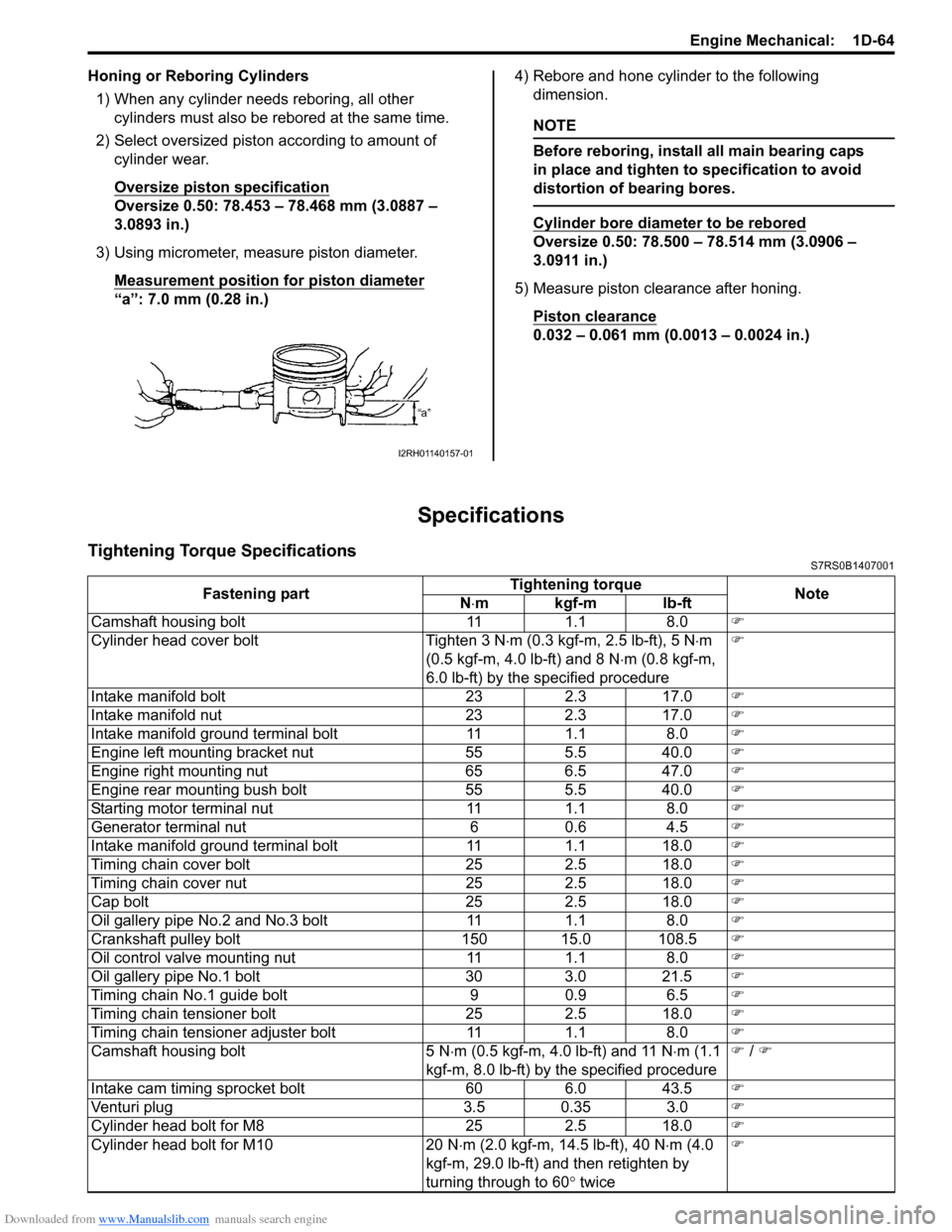
3) Using micrometer, measure piston diameter. Measurement position for piston diameter
“a”: 7.0 mm (0.28 in.) 4) Rebore and hone cylinder to the following
dimension.
NOTE
Before reboring, install all main bearing caps
in place and tighten to specification to avoid
distortion of bearing bores.
Cylinder bore diameter to be rebored
Oversize 0.50: 78.500 – 78.514 mm (3.0906 –
3.0911 in.)
5) Measure piston clearance after honing. Piston clearance
0.032 – 0.061 mm (0.0013 – 0.0024 in.)
Specifications
Tightening Torque SpecificationsS7RS0B1407001
I2RH01140157-01
Fastening part Tightening torque
Note
N ⋅mkgf-mlb-ft
Camshaft housing bolt 11 1.1 8.0 )
Cylinder head cover bolt Tighten 3 N ⋅m (0.3 kgf-m, 2.5 lb-ft), 5 N ⋅m
(0.5 kgf-m, 4.0 lb-ft) and 8 N ⋅m (0.8 kgf-m,
6.0 lb-ft) by the specified procedure )
Intake manifold bolt 23 2.3 17.0 )
Intake manifold nut 23 2.3 17.0 )
Intake manifold ground terminal bolt 11 1.1 8.0 )
Engine left mounting bracket nut 55 5.5 40.0 )
Engine right mounting nut 65 6.5 47.0 )
Engine rear mounting bush bolt 55 5.5 40.0 )
Starting motor terminal nut 11 1.1 8.0 )
Generator terminal nut 6 0.6 4.5 )
Intake manifold ground terminal bolt 11 1.1 18.0 )
Timing chain cover bolt 25 2.5 18.0 )
Timing chain cover nut 25 2.5 18.0 )
Cap bolt 25 2.5 18.0 )
Oil gallery pipe No.2 and No.3 bolt 11 1.1 8.0 )
Crankshaft pulley bolt 150 15.0 108.5 )
Oil control valve mounting nut 11 1.1 8.0 )
Oil gallery pipe No.1 bolt 30 3.0 21.5 )
Timing chain No.1 guide bolt 9 0.9 6.5 )
Timing chain tensioner bolt 25 2.5 18.0 )
Timing chain tensioner adjuster bolt 11 1.1 8.0 )
Camshaft housing bolt 5 N ⋅m (0.5 kgf-m, 4.0 lb-ft) and 11 N ⋅m (1.1
kgf-m, 8.0 lb-ft) by the specified procedure )
/ )
Intake cam timing sprocket bolt 60 6.0 43.5 )
Venturi plug 3.5 0.35 3.0 )
Cylinder head bolt for M8 25 2.5 18.0 )
Cylinder head bolt for M10 20 N ⋅m (2.0 kgf-m, 14.5 lb-ft), 40 N ⋅m (4.0
kgf-m, 29.0 lb-ft) and then retighten by
turning through to 60 ° twice )
Page 358 of 1496
Downloaded from www.Manualslib.com manuals search engine 1E-6 Engine Lubrication System:
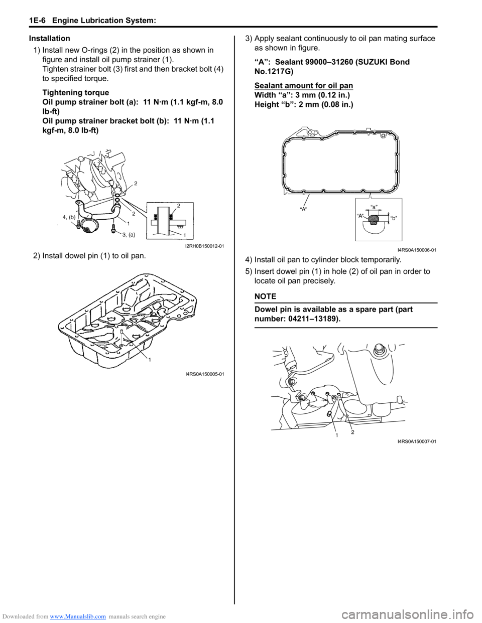
Installation1) Install new O-rings (2) in the position as shown in figure and install o il pump strainer (1).
Tighten strainer bolt (3) first and then bracket bolt (4)
to specified torque.
Tightening torque
Oil pump strainer bolt (a): 11 N·m (1.1 kgf-m, 8.0
lb-ft)
Oil pump strainer bracket bolt (b): 11 N·m (1.1
kgf-m, 8.0 lb-ft)
2) Install dowel pin (1) to oil pan. 3) Apply sealant continuously to oil pan mating surface
as shown in figure.
“A”: Sealant 99000–31260 (SUZUKI Bond
No.1217G)
Sealant amount for oil pan
Width “a”: 3 mm (0.12 in.)
Height “b”: 2 mm (0.08 in.)
4) Install oil pan to cy linder block temporarily.
5) Insert dowel pin (1) in hole (2) of oil pan in order to
locate oil pan precisely.
NOTE
Dowel pin is available as a spare part (part
number: 04211–13189).
I2RH0B150012-01
I4RS0A150005-01
I4RS0A150006-01
21I4RS0A150007-01
Page 405 of 1496

Downloaded from www.Manualslib.com manuals search engine Starting System: 1I-4
Repair Instructions
Starting Motor Dismounting and RemountingS7RS0B1906001
Dismounting1) Disconnect negative (–) battery lead at battery.
2) Disconnect magnetic switch lead wire (1) and battery cable (2) from starting motor terminals.
3) Detach shift & select control cable bracket from transaxle. (M/T model only)
4) Remove starting motor mount bolt (3) and nut (4).
5) Remove starting motor (5).
Remounting
Reverse the dismounting procedure noting the following.
• Tighten battery cable nut (6) to specified torque.
Tightening torque
Starting motor battery cable nut (a): 9.8 N·m (0.98 kgf-m, 7.0 lb-ft)
I4RS0A190002-01
: 9.8 N ⋅m (0.98 kgf-m, 7.0 lb-ft)
Page 419 of 1496
Downloaded from www.Manualslib.com manuals search engine Charging System: 1J-9
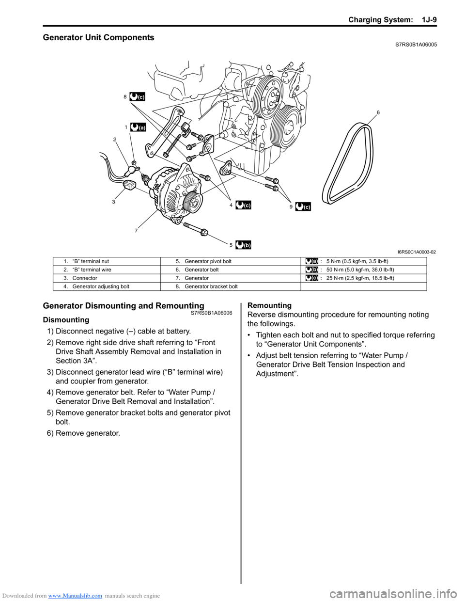
Generator Unit ComponentsS7RS0B1A06005
Generator Dismounting and RemountingS7RS0B1A06006
Dismounting1) Disconnect negative (–) cable at battery.
2) Remove right side drive shaft referring to “Front Drive Shaft Assembly Removal and Installation in
Section 3A”.
3) Disconnect generator lead wire (“B” terminal wire) and coupler from generator.
4) Remove generator belt. Refer to “Water Pump / Generator Drive Belt Re moval and Installation”.
5) Remove generator bracket bolts and generator pivot bolt.
6) Remove generator. Remounting
Reverse dismounting procedure for remounting noting
the followings.
• Tighten each bolt and nut to specified torque referring
to “Generator Unit Components”.
• Adjust belt tension referring to “Water Pump / Generator Drive Belt Tension Inspection and
Adjustment”.
(a)
(b)
(c)
1
2 8
3 7 5 49 6(c)
(c)
I6RS0C1A0003-02
1. “B” terminal nut
5. Generator pivot bolt : 5 N⋅m (0.5 kgf-m, 3.5 lb-ft)
2. “B” terminal wire 6. Generator belt : 50 N⋅m (5.0 kgf-m, 36.0 lb-ft)
3. Connector 7. Generator : 25 N⋅m (2.5 kgf-m, 18.5 lb-ft)
4. Generator adjusting bolt 8. Generator bracket bolt
Page 438 of 1496
Downloaded from www.Manualslib.com manuals search engine 2B-5 Front Suspension:
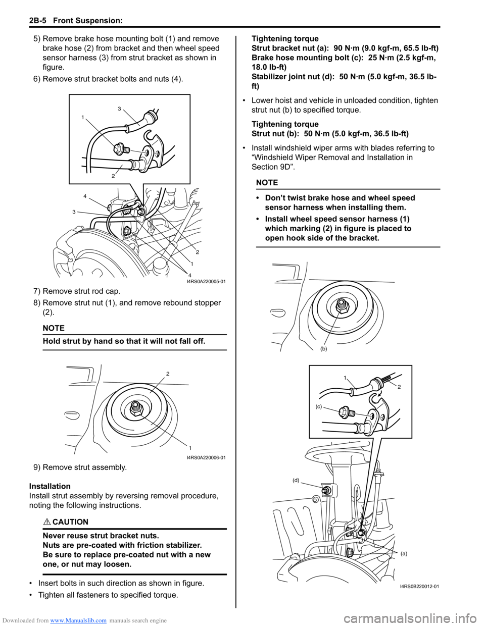
5) Remove brake hose mounting bolt (1) and remove brake hose (2) from bracket and then wheel speed
sensor harness (3) from strut bracket as shown in
figure.
6) Remove strut bracket bolts and nuts (4).
7) Remove strut rod cap.
8) Remove strut nut (1), and remove rebound stopper (2).
NOTE
Hold strut by hand so th at it will not fall off.
9) Remove strut assembly.
Installation
Install strut assembly by reversing removal procedure,
noting the following instructions.
CAUTION!
Never reuse strut bracket nuts.
Nuts are pre-coated with friction stabilizer.
Be sure to replace pre-coated nut with a new
one, or nut may loosen.
• Insert bolts in such direction as shown in figure.
• Tighten all fasteners to specified torque. Tightening torque
Strut bracket nut (a): 90 N·m (9.0 kgf-m, 65.5 lb-ft)
Brake hose mounting bolt (c): 25 N·m (2.5 kgf-m,
18.0 lb-ft)
Stabilizer joint nut (d): 50 N·m (5.0 kgf-m, 36.5 lb-
ft)
• Lower hoist and vehicle in unloaded condition, tighten strut nut (b) to specified torque.
Tightening torque
Strut nut (b): 50 N·m (5.0 kgf-m, 36.5 lb-ft)
• Install windshield wiper arms with blades referring to
“Windshield Wiper Removal and Installation in
Section 9D”.
NOTE
• Don’t twist brake hose and wheel speed sensor harness when installing them.
• Install wheel speed sensor harness (1) which marking (2) in figure is placed to
open hook side of the bracket.
1 3
2
2
1
4
4
3
I4RS0A220005-01
2
1
I4RS0A220006-01
(d) (a)
(b)
(c)
1
2
I4RS0B220012-01
Page 440 of 1496
Downloaded from www.Manualslib.com manuals search engine 2B-7 Front Suspension:
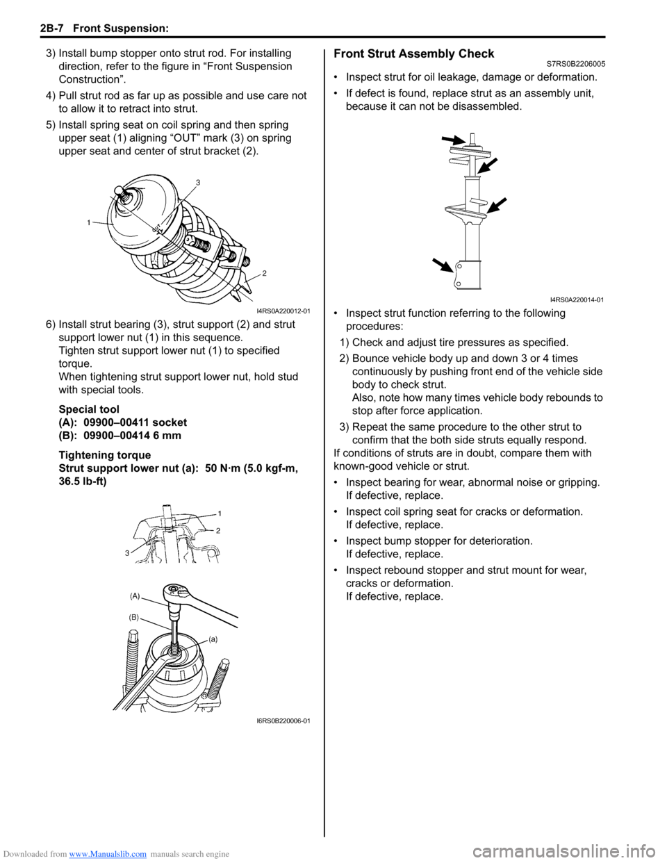
3) Install bump stopper onto strut rod. For installing
direction, refer to the figure in “Front Suspension
Construction”.
4) Pull strut rod as far up as possible and use care not to allow it to re tract into strut.
5) Install spring seat on coil spring and then spring upper seat (1) aligning “OUT” mark (3) on spring
upper seat and center of strut bracket (2).
6) Install strut bearing (3), strut support (2) and strut
support lower nut (1) in this sequence.
Tighten strut support lower nut (1) to specified
torque.
When tightening strut support lower nut, hold stud
with special tools.
Special tool
(A): 09900–00411 socket
(B): 09900–00414 6 mm
Tightening torque
Strut support lower nut (a): 50 N·m (5.0 kgf-m,
36.5 lb-ft)Front Strut Assembly CheckS7RS0B2206005
• Inspect strut for oil leakage, damage or deformation.
• If defect is found, replace strut as an assembly unit, because it can not be disassembled.
• Inspect strut function re ferring to the following
procedures:
1) Check and adjust tire pressures as specified.
2) Bounce vehicle body up and down 3 or 4 times continuously by pushing front end of the vehicle side
body to check strut.
Also, note how many times vehicle body rebounds to
stop after force application.
3) Repeat the same procedure to the other strut to confirm that the both side struts equally respond.
If conditions of struts are in doubt, compare them with
known-good vehicle or strut.
• Inspect bearing for wear, abnormal noise or gripping. If defective, replace.
• Inspect coil spring seat for cracks or deformation.
If defective, replace.
• Inspect bump stopper for deterioration. If defective, replace.
• Inspect rebound stopper and strut mount for wear, cracks or deformation.
If defective, replace.
I4RS0A220012-01
I6RS0B220006-01
I4RS0A220014-01