2007 SUZUKI SWIFT Ect sensors
[x] Cancel search: Ect sensorsPage 540 of 1496
Downloaded from www.Manualslib.com manuals search engine 4E-1 ABS:
Brakes
ABS
Precautions
Precautions in Diagnosing TroublesS7RS0B4500001
To ensure that the trouble diagnosis is done accurately
and smoothly, observe the following and follow “ABS
Check”.
• Diagnostic information stored in ABS cont rol module
memory can be cleared as well as checked by using
SUZUKI scan tool. Before us ing scan tool, read its
Operator’s (Instruction) Manual carefully to have good
understanding as to what functions are available and
how to use it.
• If the vehicles was operated in any of the following ways, ABS warning light may light momentarily but
this does not indicate anything abnormal in ABS.
– The vehicle was driven with parking brake pulled.
– The vehicle was driven with brake dragging.
– The vehicle was stuck in mud, sand, etc.
– Wheel spin occurred while driving.
– Wheel(s) was rotated while the vehicle was jacked up.
• Be sure to read “Precautions for Electrical Circuit Service in Section 00” befo re inspection and observe
what is written there.
• Be sure to use the trouble diagnosis procedure as described in “ABS Check”. Failure to follow it may
result in incorrect diagnosis. (Some other diagnosis
trouble code may be stored by mistake in the memory
of ABS control module during inspection.)
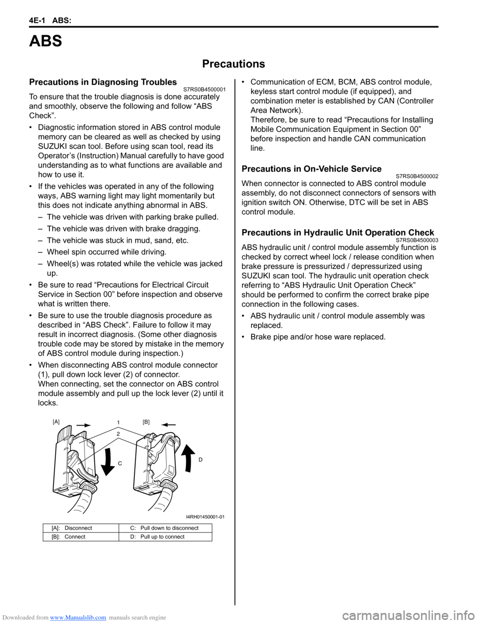
• When disconnecting ABS co ntrol module connector
(1), pull down lock lever (2) of connector.
When connecting, set the connector on ABS control
module assembly and pull up the lock lever (2) until it
locks. • Communication of ECM,
BCM, ABS control module,
keyless start control module (if equipped), and
combination meter is established by CAN (Controller
Area Network).
Therefore, be sure to read “Precautions for Installing
Mobile Communication Equipment in Section 00”
before inspection and handle CAN communication
line.
Precautions in On-Vehicle ServiceS7RS0B4500002
When connector is connected to ABS control module
assembly, do not disconnect connectors of sensors with
ignition switch ON. Otherwise, DTC will be set in ABS
control module.
Precautions in Hydraulic Unit Operation CheckS7RS0B4500003
ABS hydraulic unit / control module assembly function is
checked by correct wheel lock / release condition when
brake pressure is pressurized / depressurized using
SUZUKI scan tool. The hydraulic unit operation check
referring to “ABS Hydraulic Unit Operation Check”
should be performed to confirm the correct brake pipe
connection in the following cases.
• ABS hydraulic unit / cont rol module assembly was
replaced.
• Brake pipe and/or hose ware replaced.
[A]: Disconnect C: Pull down to disconnect
[B]: Connect D: Pull up to connect
21
C D
[A]
[B]
I4RH01450001-01
Page 546 of 1496

Downloaded from www.Manualslib.com manuals search engine 4E-7 ABS:
Component Location
ABS Components LocationS7RS0B4503001
Front Wheel Speed Sensor Components LocationS7RS0B4503002
14
5
3
2 2
2
2
6
6
6
6
7
8
I6RS0C450005-01
1. ABS hydraulic unit / control module assembly
5. EBD warning light (Brake warning light)
2. Wheel speed sensors 6. Wheel speed sensor rings
3. Stop lamp switch 7. Data link connector
4. ABS warning light 8. ECM
[A]
[B]
1 1
2
3
4
1
(a)
(b)
5I6RS0C450016-01
[A]: OK 2. Grommet5. Front wheel bearing
[B]: NG 3. Connector: 25 N⋅m (2.5 kgf-m, 18.0 lb-ft)
1. Front wheel speed sensor 4. Sensor ring: 11 N⋅m (1.1 kgf-m, 8.0 lb-ft)
Page 575 of 1496
Downloaded from www.Manualslib.com manuals search engine Electronic Stability Program: 4F-1
Brakes
Electronic Stability Program
Precautions
Precautions in Diagnosing TroublesS7RS0B4600001
To ensure that the trouble diagnosis is done accurately
and smoothly, observe the following and follow
“Electronic Stability Program System Check”.
• Diagnostic information stored in ESP® control module
memory can be cleared as well as checked by using
SUZUKI scan tool. Before us ing scan tool, read its
Operator’s (Instruction) Manual carefully to have good
understanding as to what functions are available and
how to use it.
• If the vehicles was operated in any of the following ways, ESP ® warning lamp may light momentarily but
this does not indicate anything abnormal in ESP ®.
– The vehicle was driven with parking brake pulled.
– The vehicle was driven with brake dragging.
– The vehicle was stuck in mud, sand, etc.
– Wheel spin occurred while driving.
– Wheel(s) was rotated while the vehicle was jacked up.
• Be sure to use the trouble diagnosis procedure as described in “Electronic Stability Program System
Check”. Failure to follow it may resu lt in incorrect
diagnosis. (Some other diagnosis trouble code may
be stored by mistake in the memory of ESP ® control
module during inspection.)
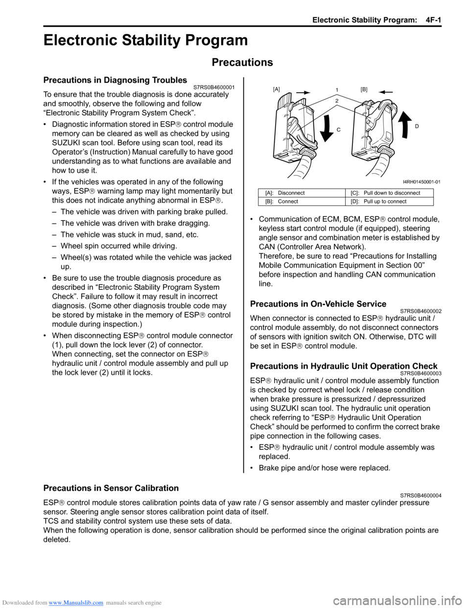
• When disconnecting ESP ® control module connector
(1), pull down the lock lever (2) of connector.
When connecting, set the connector on ESP ®
hydraulic unit / control module assembly and pull up
the lock lever (2) until it locks. • Communication of ECM, BCM, ESP
® control module,
keyless start control module (if equipped), steering
angle sensor and combination meter is established by
CAN (Controller Area Network).
Therefore, be sure to read “Precautions for Installing
Mobile Communication Equipment in Section 00”
before inspection and handling CAN communication
line.
Precautions in On-Vehicle ServiceS7RS0B4600002
When connector is connected to ESP ® hydraulic unit /
control module assembly, do not disconnect connectors
of sensors with ignition switch ON. Otherwise, DTC will
be set in ESP ® control module.
Precautions in Hydraulic Unit Operation CheckS7RS0B4600003
ESP® hydraulic unit / control module assembly function
is checked by correct wheel lock / release condition
when brake pressure is pressurized / depressurized
using SUZUKI scan tool. The hydraulic unit operation
check referring to “ESP ® Hydraulic Unit Operation
Check” should be performed to confirm the correct brake
pipe connection in the following cases.
• ESP® hydraulic unit / contro l module assembly was
replaced.
• Brake pipe and/or hose were replaced.
Precautions in Sensor CalibrationS7RS0B4600004
ESP ® control module stores calibration points data of yaw rate / G sensor assembly and master cylinder pressure
sensor. Steering angle sensor stores calibration point data of itself.
TCS and stability control system use these sets of data.
When the following operation is done, sensor calibration should be performed since the original calibration points are
deleted.
[A]: Disconnect [C]: Pull down to disconnect
[B]: Connect [D]: Pull up to connect
21
C D
[A]
[B]
I4RH01450001-01
Page 887 of 1496

Downloaded from www.Manualslib.com manuals search engine Power Assisted Steering System: 6C-5
Terminal Arrangement of P/S Control Module Coupler (Viewed from Harness Side)
Diagnostic Information and Procedures
EPS System CheckS7RS0B6304001
WARNING!
Carry out test drive in light traffic area to prevent an accident.
Refer to the following items for the details of each step.Terminal Circuit Terminal Circuit
E49-1 Main power supply for internal memory
and EPS motor E52-9 Ground for torque sensors
E49-2 Ground for P/S control module E52-10 —
E51-1 Motor output 1 E52-11 Serial communication for data link
connector
E51-2 Motor output 2 E52-12 Engine speed signal
E52-1 Ignition switch signal for P/S control
module E52-13 —
E52-2 — E52-14 P/S operation signal (idle up signal)
E52-3 — E52-15 —
E52-4 Vehicle speed signal E52-16 Torque sensor internal failure signal
E52-5 “EPS” warning light E52-17 —
E52-6 Torque sensor signal (Sub) E52-18 Torque sensor signal (Main)
E52-7 — E52-19 Ground for shield wire
E52-8 Main power supply for torque sensor E52-20 5 V reference power supply for torque
sensor
Step
Action YesNo
1 �) Customer complaint analysis
1) Perform customer complaint analysis referring to “Customer Complaint Analysis”.
Was customer complaint analysis performed? Go to Step 2.
Perform customer
complaint analysis.
2 �) DTC check, record and clearance
1) Check for DTC (including pending DTC) referring to “DTC Check”, Record and Clearance.
Is there any DTC(s)? Print DTC or write them
down and clear them by
referring to “DTC
Clearance” and go to
St ep 3 .Go to Step 4.
3 �) Visual inspection
1) Perform visual inspection referring to “Visual Inspection”.
Is there any faulty condition? Repair or replace
malfunction part, and go
to Step 11.
Go to Step 5.
4 �) Visual inspection
1) Perform visual inspection referring to “Visual Inspection”.
Is there any faulty condition? Repair or replace
malfunction part, and go
to Step 11.
Go to Step 8.
5 �) Trouble symptom confirmation
1) Confirm trouble symptom referring to “Trouble Symptom Confirmation”.
Is trouble symptom identified? Go to Step 6.
Go to Step 7.
6 �) Rechecking and record of DTC
1) Recheck for DTC referring to “DTC Check”.
Is there any DTC(s)? Go to Step 9.
Go to Step 8.
Page 918 of 1496
Downloaded from www.Manualslib.com manuals search engine 6C-36 Power Assisted Steering System:
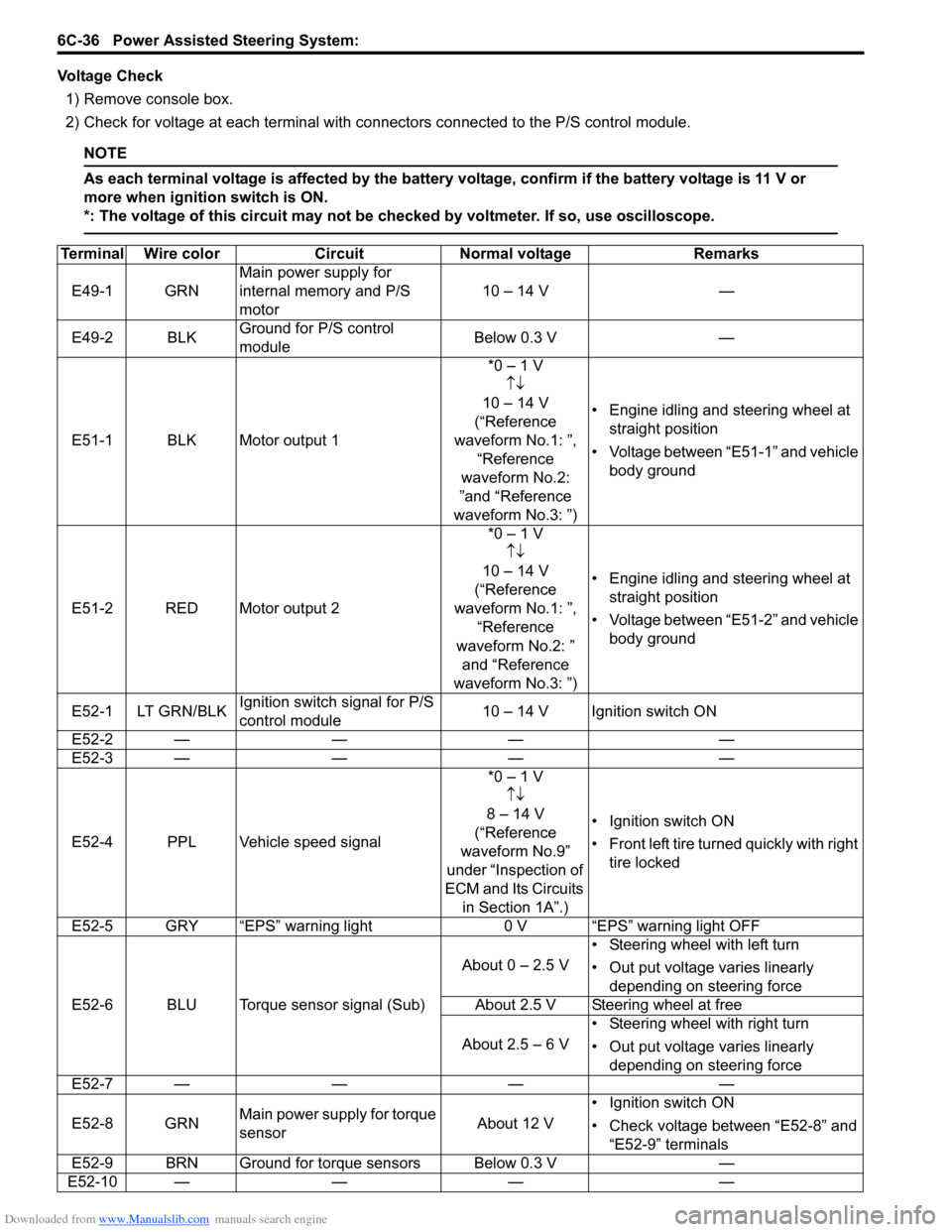
Voltage Check1) Remove console box.
2) Check for voltage at each terminal with co nnectors connected to the P/S control module.
NOTE
As each terminal voltage is affected by the battery voltage, confirm if the battery voltage is 11 V or
more when ignition switch is ON.
*: The voltage of this circuit may not be checked by voltmeter. If so, use oscilloscope.
Terminal Wire colorCircuit Normal voltage Remarks
E49-1 GRN Main power supply for
internal memory and P/S
motor 10 – 14 V
—
E49-2 BLK Ground for P/S control
module Below 0.3 V
—
E51-1 BLK Motor output 1 *0 – 1 V
↑↓
10 – 14 V
(“Reference
waveform No.1: ”, “Reference
waveform No.2:
”and “Reference
waveform No.3: ”) • Engine idling and steering wheel at
straight position
• Voltage between “E51-1” and vehicle body ground
E51-2 RED Motor output 2 *0 – 1 V
↑↓
10 – 14 V
(“Reference
waveform No.1: ”, “Reference
waveform No.2: ” and “Reference
waveform No.3: ”) • Engine idling and steering wheel at
straight position
• Voltage between “E51-2” and vehicle body ground
E52-1 LT GRN/BLK Ignition switch signal for P/S
control module 10 – 14 V Ignition switch ON
E52-2 — —— —
E52-3 — —— —
E52-4 PPL Vehicle speed signal *0 – 1 V
↑↓
8 – 14 V
(“Reference
waveform No.9”
under “Inspection of
ECM and Its Circuits in Section 1A”.) • Ignition switch ON
•Front left tire tu
rned quickly with right
tire locked
E52-5 GRY “EPS” warning light 0 V “EPS” warning light OFF
E52-6 BLU Torque sensor signal (Sub) About 0 – 2.5 V
• Steering wheel with left turn
• Out put voltage varies linearly
depending on steering force
About 2.5 V Steering wheel at free
About 2.5 – 6 V • Steering wheel with right turn
• Out put voltage varies linearly
depending on steering force
E52-7 — —— —
E52-8 GRN Main power supply for torque
sensor About 12 V• Ignition switch ON
• Check voltage between “E52-8” and
“E52-9” terminals
E52-9 BRN Ground for torque sensors Below 0.3 V —
E52-10 — —— —
Page 997 of 1496
Downloaded from www.Manualslib.com manuals search engine Air Conditioning System: Automatic Type 7B-49
Step 7. Final confirmation test
Confirm if the problem symptom is troubleshoot and the A/C system is free from any abnormal conditions. If there
existed DTC, clear the DTC. Then , check if the DTC is still detected and if there is any other DTC.
Visual InspectionS7RS0B7224009
Check visually the following parts and systems.
DTC B1502: Inside Air Temperature Sensor and/or Its Circuit MalfunctionS7RS0B7224010
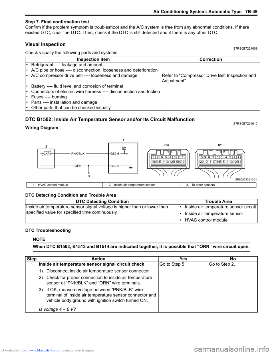
Wiring Diagram
DTC Detecting Condition and Trouble Area
DTC Troubleshooting
NOTE
When DTC B1503, B1513 and B1514 are indicated together, it is possible that “ORN” wire circuit open.
Inspection item Correction
• Refrigerant ---- leakage and amount
• A/C pipe or hose ---- disconnection, looseness and deterioration
• A/C compressor drive belt ---- looseness and damage Refer to “Compressor Drive Belt Inspection and
Adjustment”.
• Battery ---- fluid level and corrosion of terminal
• Connectors of electric wire harn ess ---- disconnection and friction
• Fuses ---- burning
• Parts ---- installation and damage
• Other parts that can be checked visually
5V
PNK/BLK
ORN G52-6
G52-3
2
1
3
7812910
65 431516 14 13 12 11
G52
789101920121112
65 431718 16 15 14 13
G51
I5RS0A722010-01
1. HVAC control module
2. Inside air temperature sensor 3. To other sensors
DTC Detecting Condition Trouble Area
Inside air temperature sensor signal voltage is higher than or lower than
specified value for specified time continuously. • Inside air temperature sensor circuit
• Inside air temperature sensor
• HVAC control module
Step
Action YesNo
1 Inside air temperature sensor signal circuit check
1) Disconnect inside air temperature sensor connector.
2) Check for proper connection to inside air temperature
sensor at “PNK/BLK” and “ORN” wire terminals.
3) If OK, measure voltage between “PNK/BLK” wire terminal of inside air temp erature sensor connector and
vehicle body ground with ignition switch turned ON.
Is voltage 4 – 6 V? Go to Step 5.
Go to Step 2.
Page 998 of 1496
Downloaded from www.Manualslib.com manuals search engine 7B-50 Air Conditioning System: Automatic Type
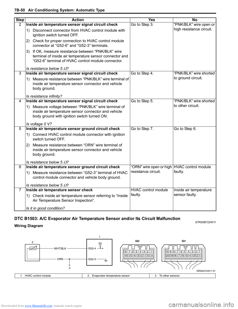
DTC B1503: A/C Evaporator Air Temperature Sensor and/or Its Circuit MalfunctionS7RS0B7224011
Wiring Diagram2
Inside air temperature sensor signal circuit check
1) Disconnect connector from HVAC control module with
ignition switch turned OFF.
2) Check for proper connection to HVAC control module connector at “G52-6” and “G52-3” terminals.
3) If OK, measure resistance between “PNK/BLK” wire terminal of inside air temp erature sensor connector and
“G52-6” terminal of HVAC control module connector.
Is resistance below 5
Ω? Go to Step 3. “PNK/BLK” wire open or
high resistance circuit.
3 Inside air temperature sensor signal circuit check
1) Measure resistance between “PNK/BLK” wire terminal of
inside air temperature sensor connector and vehicle
body ground.
Is resistance infinity? Go to Step 4.
“PNK/BLK” wire shorted
to ground circuit.
4 Inside air temperature sensor signal circuit check
1) Measure voltage between “PNK/BLK” wire terminal of
inside air temperature sensor connector and vehicle
body ground with ignition switch turned ON.
Is voltage 0 V? Go to Step 5.
“PNK/BLK” wire shorted
to other circuit.
5 Inside air temperature sensor ground circuit check
1) Connect HVAC control module connector with ignition
switch turned OFF.
2) Measure resistance between “ORN” wire terminal of inside air temperature sensor connector and vehicle
body ground.
Is resistance below 5
Ω? Go to Step 7. Go to Step 6.
6 Inside air temperature sensor ground circuit check
1) Measure resistance between “G52-3” terminal of HVAC
control module connector and vehicle body ground.
Is resistance below 5
Ω? “ORN” wire open or high
resistance circuit.
HVAC control module
faulty.
7 Inside air temperature sensor check
1) Check inside air temperature sensor referring to “Inside
Air Temperature Sensor Inspection”.
Is it in good condition? HVAC control module
faulty.
Inside air temperature
sensor faulty.
Step Action Yes No
5V
WHT/BLK
ORN G52-4
G52-3
2
1
3
7812910
65 431516 14 13 12 11
G52
789101920121112
65 431718 16 15 14 13
G51
I5RS0A722011-01
1. HVAC control module
2. Evaporator temperature sensor 3. To other sensors
Page 1001 of 1496
Downloaded from www.Manualslib.com manuals search engine Air Conditioning System: Automatic Type 7B-53
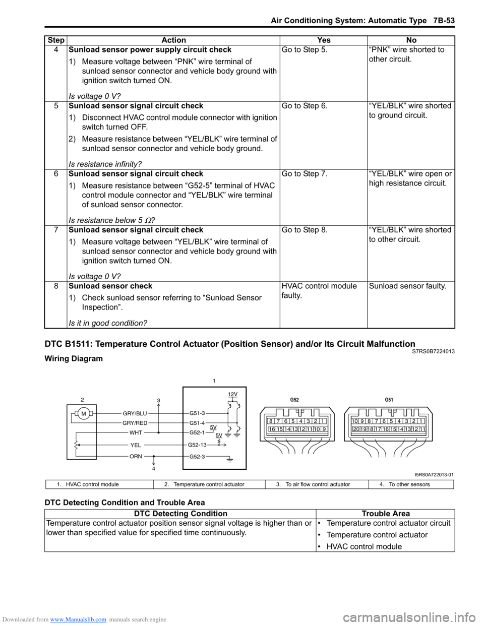
DTC B1511: Temperature Control Actuator (Position Sensor) and/or Its Circuit MalfunctionS7RS0B7224013
Wiring Diagram
DTC Detecting Condition and Trouble Area4
Sunload sensor power supply circuit check
1) Measure voltage between “PNK” wire terminal of
sunload sensor connector and vehicle body ground with
ignition switch turned ON.
Is voltage 0 V? Go to Step 5. “PNK” wire shorted to
other circuit.
5 Sunload sensor signal circuit check
1) Disconnect HVAC control modul e connector with ignition
switch turned OFF.
2) Measure resistance between “YEL/BLK” wire terminal of sunload sensor connector and vehicle body ground.
Is resistance infinity? Go to Step 6. “YEL/BLK” wire shorted
to ground circuit.
6 Sunload sensor signal circuit check
1) Measure resistance between “G52-5” terminal of HVAC
control module connector and “YEL/BLK” wire terminal
of sunload sensor connector.
Is resistance below 5
Ω? Go to Step 7. “YEL/BLK” wire open or
high resistance circuit.
7 Sunload sensor signal circuit check
1) Measure voltage between “YEL/BLK” wire terminal of
sunload sensor connector and vehicle body ground with
ignition switch turned ON.
Is voltage 0 V? Go to Step 8.
“YEL/BLK” wire shorted
to other circuit.
8 Sunload sensor check
1) Check sunload sensor referring to “Sunload Sensor
Inspection”.
Is it in good condition? HVAC control module
faulty.
Sunload sensor faulty.
Step
Action YesNo
7812910
65 431516 14 13 12 11
G52
789101920121112
65 431718 16 15 14 13
G51
M 12V
5V 5V
YEL
WHT
GRY/BLU
GRY/RED
2
1
ORN
G51-3
G51-4
G52-1
G52-13
G52-3
3
4
I5RS0A722013-01
1. HVAC control module 2. Temperature control actuator 3. To air flow control actuator4. To other sensors
DTC Detecting Condition Trouble Area
Temperature control actuator position sensor signal voltage is higher than or
lower than specified value for specified time continuously. • Temperature control actuator circuit
• Temperature control actuator
• HVAC control module