2007 SUZUKI SWIFT Ect sensors
[x] Cancel search: Ect sensorsPage 66 of 1496
Downloaded from www.Manualslib.com manuals search engine 1A-16 Engine General Information and Diagnosis:
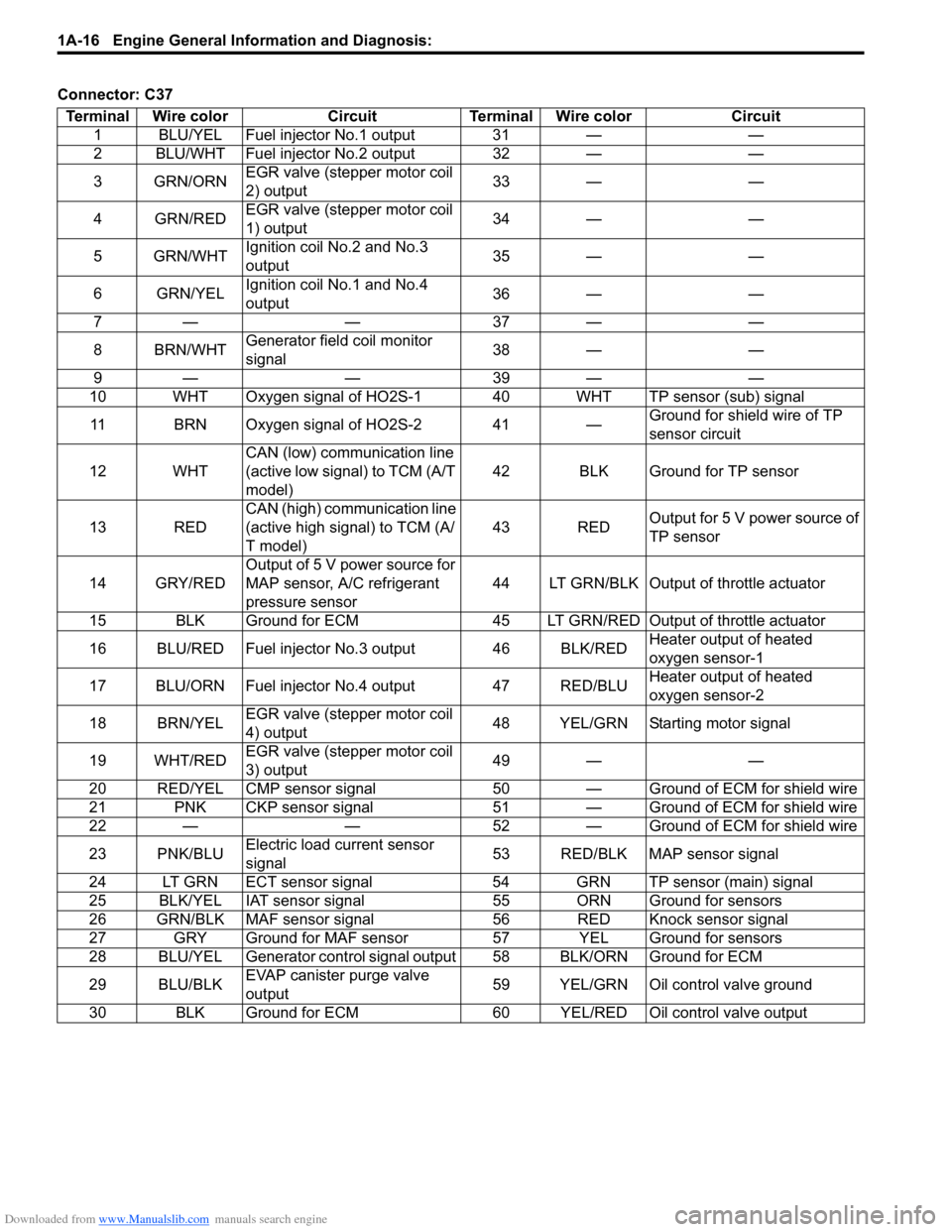
Connector: C37Terminal Wire color Circuit Terminal Wire color Circuit 1 BLU/YEL Fuel injector No.1 output 31 — —
2 BLU/WHT Fuel injector No.2 output 32 — —
3GRN/ORN EGR valve (stepper motor coil
2) output 33 — —
4 GRN/RED EGR valve (stepper motor coil
1) output 34 — —
5 GRN/WHT Ignition coil No.2 and No.3
output 35 — —
6 GRN/YEL Ignition coil No.1 and No.4
output 36 — —
7— — 37— —
8 BRN/WHT Generator field coil monitor
signal 38 — —
9— — 39— —
10 WHT Oxygen signal of HO2S-1 40 WHT TP sensor (sub) signal
11 BRN Oxygen signal of HO2S-2 41 — Ground for shield wire of TP
sensor circuit
12 WHT CAN (low) communication line
(active low signal) to TCM (A/T
model) 42 BLK Ground for TP sensor
13 RED CAN (high) communication line
(active high signal) to TCM (A/
T model) 43 RED
Output for 5 V power source of
TP sensor
14 GRY/RED Output of 5 V power source for
MAP sensor, A/C refrigerant
pressure sensor 44 LT GRN/BLK Output of throttle actuator
15 BLK Ground for ECM 45 LT GRN/RE D Output of throttle actuator
16 BLU/RED Fuel injector No.3 output 46 BLK/RED Heater output of heated
oxygen sensor-1
17 BLU/ORN Fuel injector No.4 output 47 RED/BLU Heater output of heated
oxygen sensor-2
18 BRN/YEL EGR valve (stepper motor coil
4) output 48 YEL/GRN Starting motor signal
19 WHT/RED EGR valve (stepper motor coil
3) output 49 — —
20 RED/YEL CMP sensor signal 50 — G round of ECM for shield wire
21 PNK CKP sensor signal 51 — Ground of ECM for shield wire
22 — — 52 — Ground of ECM for shield wire
23 PNK/BLU Electric load current sensor
signal 53 RED/BLK MAP sensor signal
24 LT GRN ECT sensor signal 54 GRN TP sensor (main) signal
25 BLK/YEL IAT sensor signal 55 ORN Ground for sensors
26 GRN/BLK MAF sensor signal 56 RED Knock sensor signal
27 GRY Ground for MAF sensor 57 YEL Ground for sensors
28 BLU/YEL Generator control signal output 58 BLK/ORN Ground for ECM
29 BLU/BLK EVAP canister purge valve
output 59 YEL/GRN Oil control valve ground
30 BLK Ground for ECM 60 YEL/RED Oil control valve output
Page 67 of 1496

Downloaded from www.Manualslib.com manuals search engine Engine General Information and Diagnosis: 1A-17
Connector: E23Terminal Wire color Circuit Terminal Wire color Circuit 1 BLK/RED Main power supply 31 BLK Ground for ECM
2WHT/RED Power source for ECM internal
memory 32 RED/YELPower supply of throttle
actuator drive circuit
3RED CAN communication line
(active high signal) for ABS/
ESP®
control module, BCM,
combination meter 33 — —
4BRN Engine revolution signal output
for P/S control module 34 REDOutput of 5 V power source for
APP sensor (sub)
5 PPL/WHT 12 V serial communication line
of DLC 35 BRNOutput of 5 V power source for
APP sensor (main)
6 — — 36 YEL APP sensor (sub) signal
7 — — 37 GRN APP sensor (main) signal
8— — 38— —
9— — 39— —
10——40—— 11——41——
12 BLU Diagnosis switch terminal
(Hong Kong model) 42 — —
13 YEL/RED Clock signal for immobilizer
coil antenna 43 — —
14——44——
15 GRN/WHT Fuel pump relay output 45 BLU/ORN Throttle actuator control relay
output
16 BLK/RED Main power supply 46 LT GRN Radiator cooling fan relay No.1
output
17 — — 47 GRY A/C compressor relay output
18 WHT CAN communication line
(active low signal) for ABS/
ESP®
control module BCM,
combination meter 48 GRN
Radiator cooling fan relay No.2
and No.3 output
19 BLU/WHT Electric load signal for heater
blower motor 49 — —
20 GRN/WHT Brake light switch signal 50 — Ground for shield wire of APP
sensor
21 — — 51 WHT Ground for APP sensor (sub)
22 — — 52 BLU Ground for APP sensor (main)
23——53——
24 — — 54 ORN Ground for sensors
25 PPL Vehicle speed signal output for
P/S control module 55 REDA/C refrigerant pressure
sensor signal
26 RED/BLU EPS signal 56 — —
27 — — 57 WHT/BLK A/C evaporator outlet air temp.
sensor signal (Manual A/C
model)
28 YEL/BLK Serial communication line for
immobilizer coil antenna 58 — —
29 BLK/WHT Ignition switch signal 59 — —
30 WHT Starting motor control relay
output 60 BRN/WHT Main power supply relay output
Page 71 of 1496
Downloaded from www.Manualslib.com manuals search engine Engine General Information and Diagnosis: 1A-21
Component Location
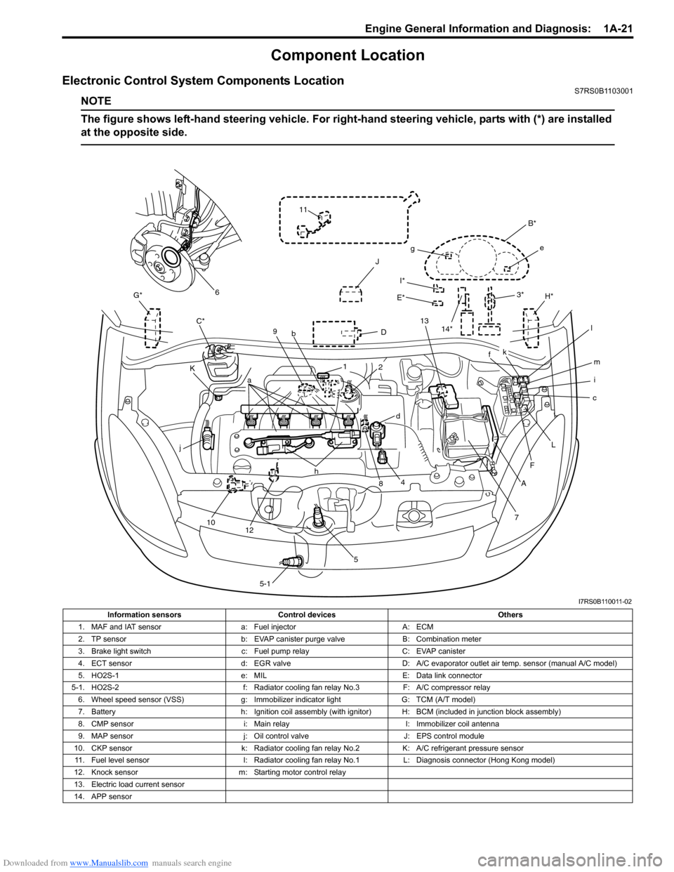
Electronic Control System Components LocationS7RS0B1103001
NOTE
The figure shows left-hand steering vehicle. For right-hand steering vehicle, parts with (*) are installed
at the opposite side.
I*
E*
G*
D
K H*
J
C*
7
A
F
c
L
i m
f
B*
e
g
k
l
13
3*
4
j
10 12 h
58
a
9
b
1
5-1
d
2
11
6
14*
I7RS0B110011-02
Information sensors Control devices Others
1. MAF and IAT sensor a: Fuel injectorA: ECM
2. TP sensor b: EVAP canister purge valve B: Combination meter
3. Brake light switch c: Fuel pump relayC: EVAP canister
4. ECT sensor d: EGR valveD: A/C evaporator outlet air temp. sensor (manual A/C model)
5. HO2S-1 e: MILE: Data link connector
5-1. HO2S-2 f: Radiator cooling fan relay No.3F: A/C compressor relay
6. Wheel speed sensor (VSS) g: Immobilizer indicator lightG: TCM (A/T model)
7. Battery h: Ignition coil assembly (with ignitor) H: BCM (included in junction block assembly)
8. CMP sensor i: Main relayI: Immobilizer coil antenna
9. MAP sensor j: Oil control valveJ: EPS control module
10. CKP sensor k: Radiator cooling fan relay No.2K: A/C refrigerant pressure sensor
11. Fuel level sensor l: Radiator cooling fan relay No.1L: Diagnosis connector (Hong Kong model)
12. Knock sensor m: Starting motor control relay
13. Electric load current sensor
14. APP sensor
Page 108 of 1496
Downloaded from www.Manualslib.com manuals search engine 1A-58 Engine General Information and Diagnosis:
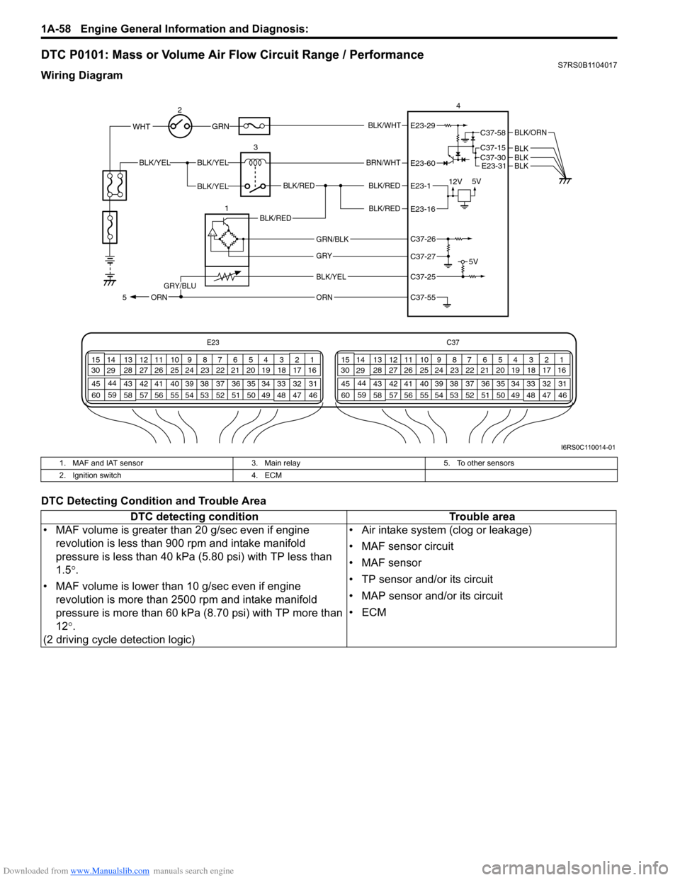
DTC P0101: Mass or Volume Air Flow Circuit Range / PerformanceS7RS0B1104017
Wiring Diagram
DTC Detecting Condition and Trouble Area
E23C37
34
1819
567
1011
17
20
47 46
495051
2122
52 16
25 9
24
14
29
55
57 54 53
59
60 58 2
262728
15
30
56 4832 31
34353637
40
42 39 38
44
45 43 41 331
1213
238
34
1819
567
1011
17
20
47 46
495051
2122
52 16
25 9
24
14
29
55
57 54 53
59
60 58 2
262728
15
30
56 4832 31
34353637
40
42 39 38
44
45 43 41 331
1213
238
BLK/WHT
BLK/RED
BLK/RED
WHT
BLK/YELBLK/YEL
BLK/YEL
GRN
BRN/WHT
12V 5V
5V
2 3 4
E23-29
E23-60
E23-1
E23-16
BLK/ORN
BLKBLK
BLK/RED
BLK/YELGRY/BLU
ORN
1BLK/RED
5
E23-31BLK
ORN
GRY
GRN/BLK
C37-58
C37-15
C37-30
C37-26
C37-27
C37-25
C37-55
I6RS0C110014-01
1. MAF and IAT sensor
3. Main relay5. To other sensors
2. Ignition switch 4. ECM
DTC detecting condition Trouble area
• MAF volume is greater than 20 g/sec even if engine revolution is less than 900 rpm and intake manifold
pressure is less than 40 kPa (5.80 psi) with TP less than
1.5 °.
• MAF volume is lower than 10 g/sec even if engine
revolution is more than 2500 rpm and intake manifold
pressure is more than 60 kPa (8.70 psi) with TP more than
12 °.
(2 driving cycle detection logic) • Air intake system (clog or leakage)
• MAF sensor circuit
•MAF sensor
• TP sensor and/or its circuit
• MAP sensor and/or its circuit
•ECM
Page 114 of 1496
Downloaded from www.Manualslib.com manuals search engine 1A-64 Engine General Information and Diagnosis:
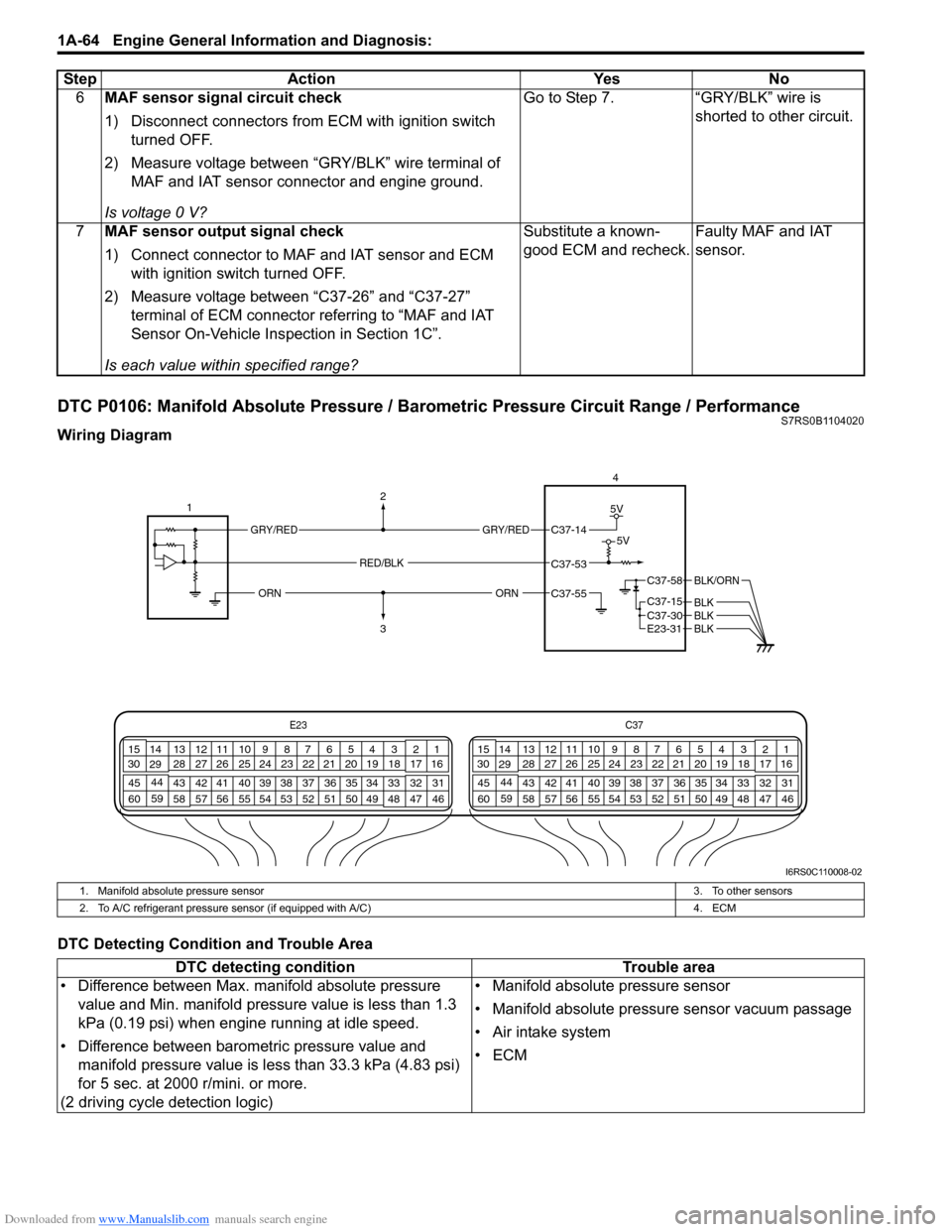
DTC P0106: Manifold Absolute Pressure / Barometric Pressure Circuit Range / PerformanceS7RS0B1104020
Wiring Diagram
DTC Detecting Condition and Trouble Area6
MAF sensor signal circuit check
1) Disconnect connectors from ECM with ignition switch
turned OFF.
2) Measure voltage between “GRY/BLK” wire terminal of MAF and IAT sensor connector and engine ground.
Is voltage 0 V? Go to Step 7. “GRY/BLK” wire is
shorted to other circuit.
7 MAF sensor output signal check
1) Connect connector to MAF and IAT sensor and ECM
with ignition swit ch turned OFF.
2) Measure voltage between “C37-26” and “C37-27” terminal of ECM connector referring to “MAF and IAT
Sensor On-Vehicle Inspection in Section 1C”.
Is each value within specified range? Substitute a known-
good ECM and recheck.
Faulty MAF and IAT
sensor.
Step Action Yes No
E23
C37
34
1819
567
1011
17
20
47 46
495051
2122
52 16
25 9
24
14
29
55
57 54 53
59
60 58 2
262728
15
30
56 4832 31
34353637
40
42 39 38
44
45 43 41 331
1213
238
34
1819
567
1011
17
20
47 46
495051
2122
52 16
25 9
24
14
29
55
57 54 53
59
60 58 2
262728
15
30
56 4832 31
34353637
40
42 39 38
44
45 43 41 331
1213
238
4
C37-58
C37-15 C37-30
BLK/ORN
BLKBLKE23-31 BLK
1
2
3
GRY/REDGRY/RED
5V
5VC37-14
C37-53
C37-55
RED/BLK
ORNORN
I6RS0C110008-02
1. Manifold absolute pressure sensor
3. To other sensors
2. To A/C refrigerant pressure sensor (if equipped with A/C) 4. ECM
DTC detecting condition Trouble area
• Difference between Max. manifold absolute pressure value and Min. manifold pressure value is less than 1.3
kPa (0.19 psi) when engine running at idle speed.
• Difference between barometric pressure value and manifold pressure value is less than 33.3 kPa (4.83 psi)
for 5 sec. at 2000 r/mini. or more.
(2 driving cycle detection logic) • Manifold absolute pressure sensor
• Manifold absolute pressure sensor vacuum passage
• Air intake system
•ECM
Page 119 of 1496
Downloaded from www.Manualslib.com manuals search engine Engine General Information and Diagnosis: 1A-69
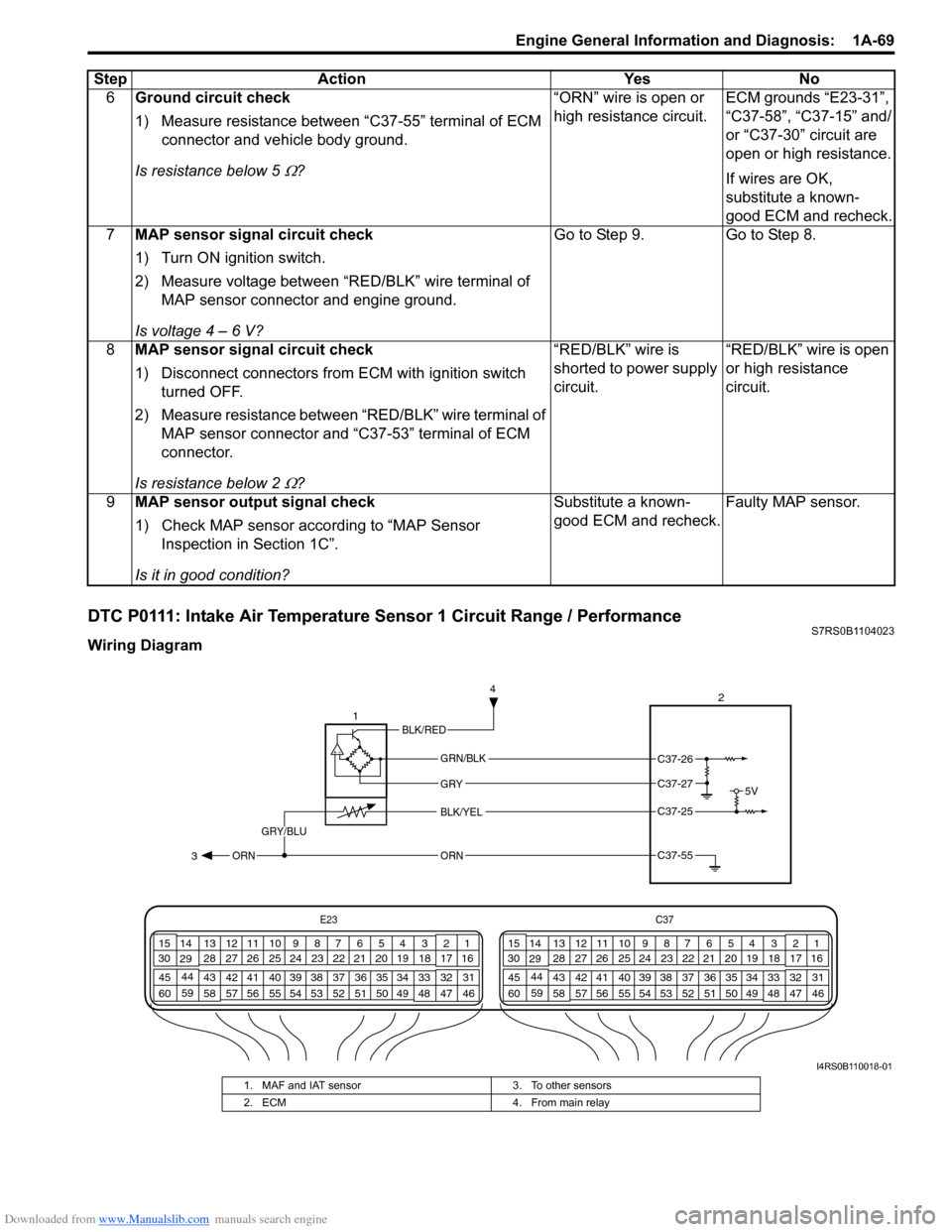
DTC P0111: Intake Air Temperature Sensor 1 Circuit Range / PerformanceS7RS0B1104023
Wiring Diagram6
Ground circuit check
1) Measure resistance between “C37-55” terminal of ECM
connector and vehicle body ground.
Is resistance below 5
Ω? “ORN” wire is open or
high resistance circuit.
ECM grounds “E23-31”,
“C37-58”, “C37-15” and/
or “C37-30” circuit are
open or high resistance.
If wires are OK,
substitute a known-
good ECM and recheck.
7 MAP sensor signal circuit check
1) Turn ON ignition switch.
2) Measure voltage between “RED/BLK” wire terminal of
MAP sensor connector and engine ground.
Is voltage 4 – 6 V? Go to Step 9. Go to Step 8.
8 MAP sensor signal circuit check
1) Disconnect connectors from ECM with ignition switch
turned OFF.
2) Measure resistance between “RED/BLK” wire terminal of MAP sensor connector and “C37-53” terminal of ECM
connector.
Is resistance below 2
Ω? “RED/BLK” wire is
shorted to power supply
circuit.
“RED/BLK” wire is open
or high resistance
circuit.
9 MAP sensor output signal check
1) Check MAP sensor acco rding to “MAP Sensor
Inspection in Section 1C”.
Is it in good condition? Substitute a known-
good ECM and recheck.
Faulty MAP sensor.
Step Action Yes No
E23
C37
34
1819
567
1011
17
20
47 46
495051
2122
52 16
25 9
24
14
29
55
57 54 53
59
60 58 2
262728
15
30
56 4832 31
34353637
40
42 39 38
44
45 43 41 331
1213
238
34
1819
567
1011
17
20
47 46
495051
2122
52 16
25 9
24
14
29
55
57 54 53
59
60 58 2
262728
15
30
56 4832 31
34353637
40
42 39 38
44
45 43 41 331
1213
238
5V
2
BLK/YEL
GRY/BLU
GRY
ORN
1
GRN/BLK
C37-25
C37-55 3 4ORN
C37-26
C37-27
BLK/RED
I4RS0B110018-01
1. MAF and IAT sensor
3. To other sensors
2. ECM 4. From main relay
Page 126 of 1496
Downloaded from www.Manualslib.com manuals search engine 1A-76 Engine General Information and Diagnosis:
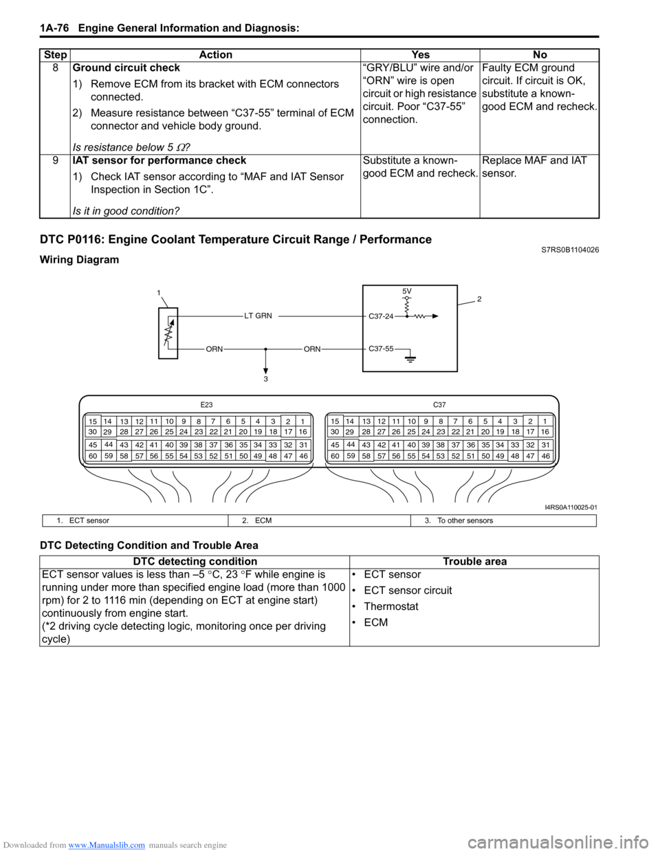
DTC P0116: Engine Coolant Temperature Circuit Range / PerformanceS7RS0B1104026
Wiring Diagram
DTC Detecting Condition and Trouble Area8
Ground circuit check
1) Remove ECM from its br acket with ECM connectors
connected.
2) Measure resistance between “C37-55” terminal of ECM connector and vehicle body ground.
Is resistance below 5
Ω? “GRY/BLU” wire and/or
“ORN” wire is open
circuit or high resistance
circuit. Poor “C37-55”
connection.
Faulty ECM ground
circuit. If circuit is OK,
substitute a known-
good ECM and recheck.
9 IAT sensor for performance check
1) Check IAT sensor according to “MAF and IAT Sensor
Inspection in Section 1C”.
Is it in good condition? Substitute a known-
good ECM and recheck.
Replace MAF and IAT
sensor.
Step Action Yes No
C37-55ORNORN
3
1
2
5V
C37-24LT GRN
E23
C37
34
1819
567
1011
17
20
47 46
495051
2122
52 16
25 9
24
14
29
55
57 54 53
59
60 58 2
262728
15
30
56 48 32 31
34353637
40
42 39 38
44
45 43 41 331
1213
238
34
1819
567
1011
17
20
47 46
495051
2122
52 16
25 9
24
14
29
55
57 54 53
59
60 58 2
262728
15
30
56 4832 31
34353637
40
42 39 38
44
45 43 41 331
1213
238
I4RS0A110025-01
1. ECT sensor
2. ECM3. To other sensors
DTC detecting condition Trouble area
ECT sensor values is less than –5 °C, 23 °F while engine is
running under more than specified engine load (more than 1000
rpm) for 2 to 1116 min (depending on ECT at engine start)
continuously from engine start.
(*2 driving cycle detecting logi c, monitoring once per driving
cycle) • ECT sensor
• ECT sensor circuit
•Thermostat
•ECM
Page 156 of 1496
Downloaded from www.Manualslib.com manuals search engine 1A-106 Engine General Information and Diagnosis:
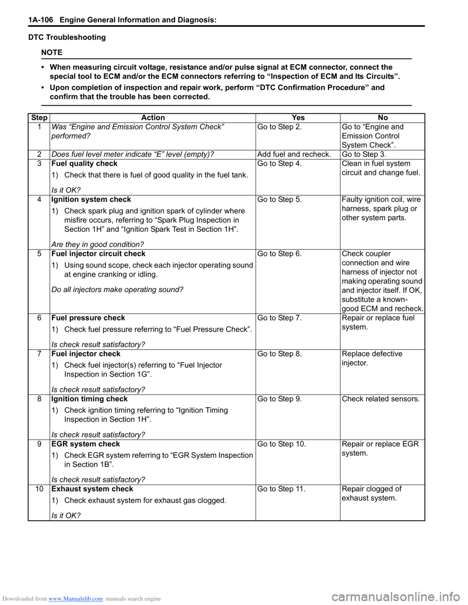
DTC Troubleshooting
NOTE
• When measuring circuit voltage, resistance and/or pulse signal at ECM connector, connect the
special tool to ECM and/or the ECM connectors re ferring to “Inspection of ECM and Its Circuits”.
• Upon completion of inspection and repair work, perform “DTC Confirmation Procedure” and confirm that the trouble has been corrected.
Step Action YesNo
1 Was “Engine and Emission Control System Check”
performed? Go to Step 2.
Go to “Engine and
Emission Control
System Check”.
2 Does fuel level meter in dicate “E” level (empty)? Add fuel and recheck. Go to Step 3.
3 Fuel quality check
1) Check that there is fuel of good quality in the fuel tank.
Is it OK? Go to Step 4.
Clean in fuel system
circuit and change fuel.
4 Ignition system check
1) Check spark plug and ignition spark of cylinder where
misfire occurs, referring to “Spark Plug Inspection in
Section 1H” and “Ignition Spark Test in Section 1H”.
Are they in good condition? Go to Step 5.
Faulty ignition coil, wire
harness, spark plug or
other system parts.
5 Fuel injector circuit check
1) Using sound scope, check each injector operating sound
at engine cranking or idling.
Do all injectors ma ke operating sound? Go to Step 6.
Check coupler
connection and wire
harness of injector not
making operating sound
and injector itself. If OK,
substitute a known-
good ECM and recheck.
6 Fuel pressure check
1) Check fuel pressure referring to “Fuel Pressure Check”.
Is check result satisfactory? Go to Step 7.
Repair or replace fuel
system.
7 Fuel injector check
1) Check fuel injector(s) re ferring to “Fuel Injector
Inspection in Section 1G”.
Is check result satisfactory? Go to Step 8.
Replace defective
injector.
8 Ignition timing check
1) Check ignition timing referring to “Ignition Timing
Inspection in Section 1H”.
Is check result satisfactory? Go to Step 9.
Check related sensors.
9 EGR system check
1) Check EGR system referring to “EGR System Inspection
in Section 1B”.
Is check result satisfactory? Go to Step 10. Repair or replace EGR
system.
10 Exhaust system check
1) Check exhaust system for exhaust gas clogged.
Is it OK? Go to Step 11. Repair clogged of
exhaust system.