2007 SUZUKI SWIFT 9a 102
[x] Cancel search: 9a 102Page 330 of 1496
Downloaded from www.Manualslib.com manuals search engine 1D-45 Engine Mechanical:
Pistons, Piston Rings, Connecting Rods and
Cylinders Removal and Installation
S7RS0B1406030
Removal1) Remove engine assembly from vehicle referring to “Engine Assembly Removal and Installation”.
2) Remove cylinder head referring to “Valves and Cylinder Head Removal and Installation”.
3) Mark cylinder number on all pistons, connecting rods
and connecting rod caps using silver pencil or quick
drying paint.
4) Remove rod bearing caps.
5) Decarbonize top of cylinder bore before removing piston from cylinder.
6) Push piston and connecting rod assembly out through the top of cylinder bore.
Installation 1) Apply engine oil to pistons, rings, cylinder walls, connecting rod bearings and crank pins.
NOTE
Do not apply oil between connecting rod and
bearing or between bearing cap and bearing.
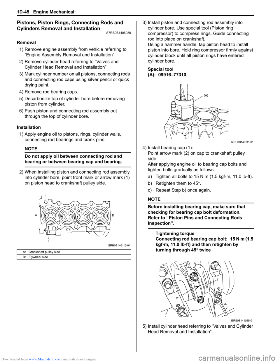
2) When installing piston and connecting rod assembly into cylinder bore, point front mark or arrow mark (1)
on piston head to crankshaft pulley side. 3) Install piston and connecting rod assembly into
cylinder bore. Use special tool (Piston ring
compressor) to compress rings. Guide connecting
rod into place on crankshaft.
Using a hammer handle, tap piston head to install
piston into bore. Hold ring compressor firmly against
cylinder block until all piston rings have entered
cylinder bore.
Special tool
(A): 09916–77310
4) Install bearing cap (1): Point arrow mark (2) on cap to crankshaft pulley
side.
After applying engine oil to bearing cap bolts and
tighten bolts gradually as follows.
a) Tighten all bolts to 15 N ⋅m (1.5 kgf-m, 11.0 lb-ft).
b) Retighten them to 45 °.
c) Repeat Step b) once again.
NOTE
Before installing bearing cap, make sure that
checking for bearing cap bolt deformation.
Refer to “Piston Pins and Connecting Rods
Inspection”.
Tightening torque
Connecting rod bearing cap bolt: 15 N ⋅m (1.5
kgf-m, 11.0 lb-ft) and then retighten by
turning through 45 ° twice
5) Install cylinder head referring to “Valves and Cylinder Head Removal and Installation”.
A: Crankshaft pulley side
B: Flywheel side
I2RH0B140110-01
I2RH0B140111-01
I6RS0B141025-01
Page 336 of 1496
Downloaded from www.Manualslib.com manuals search engine 1D-51 Engine Mechanical:
Connecting Rod Bearing Clearance1) Before checking bearing clearance, clean bearing and crank pin.
2) Install bearing in connecting rod and bearing cap.
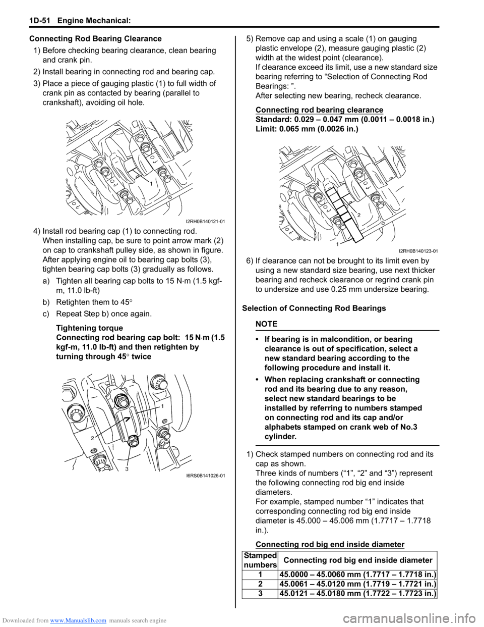
3) Place a piece of gauging plastic (1) to full width of crank pin as contacted by bearing (parallel to
crankshaft), avoiding oil hole.
4) Install rod bearing cap (1) to connecting rod. When installing cap, be sure to point arrow mark (2)
on cap to crankshaft pulley side, as shown in figure.
After applying engine oil to bearing cap bolts (3),
tighten bearing cap bolts (3) gradually as follows.
a) Tighten all bearing cap bolts to 15 N ⋅m (1.5 kgf-
m, 11.0 lb-ft)
b) Retighten them to 45°
c) Repeat Step b) once again.
Tightening torque
Connecting rod bearing cap bolt: 15 N ⋅m (1.5
kgf-m, 11.0 lb-ft) and then retighten by
turning through 45 ° twice 5) Remove cap and using a scale (1) on gauging
plastic envelope (2), measure gauging plastic (2)
width at the widest point (clearance).
If clearance exceed its limit, use a new standard size
bearing referring to “Selection of Connecting Rod
Bearings: ”.
After selecting new bearing, recheck clearance.
Connecting rod bearing clearance
Standard: 0.029 – 0.047 mm (0.0011 – 0.0018 in.)
Limit: 0.065 mm (0.0026 in.)
6) If clearance can not be brought to its limit even by using a new standard size bearing, use next thicker
bearing and recheck clearance or regrind crank pin
to undersize and use 0.25 mm undersize bearing.
Selection of Connecting Rod Bearings
NOTE
• If bearing is in malcondition, or bearing clearance is out of specification, select a
new standard bearing according to the
following procedure and install it.
• When replacing crankshaft or connecting rod and its bearing due to any reason,
select new standard bearings to be
installed by referring to numbers stamped
on connecting rod and its cap and/or
alphabets stamped on crank web of No.3
cylinder.
1) Check stamped numbers on connecting rod and its cap as shown.
Three kinds of numbers (“1”, “2” and “3”) represent
the following connecting rod big end inside
diameters.
For example, stamped number “1” indicates that
corresponding connecting rod big end inside
diameter is 45.000 – 45.006 mm (1.7717 – 1.7718
in.).
Connecting rod big end inside diameter
I2RH0B140121-01
I6RS0B141026-01
Stamped
numbers Connecting rod big end inside diameter
1 45.0000 – 45.0060 mm (1.7717 – 1.7718 in.)
2 45.0061 – 45.0120 mm (1.7719 – 1.7721 in.)
3 45.0121 – 45.0180 mm (1.7722 – 1.7723 in.)
I2RH0B140123-01
Page 337 of 1496
Downloaded from www.Manualslib.com manuals search engine Engine Mechanical: 1D-52
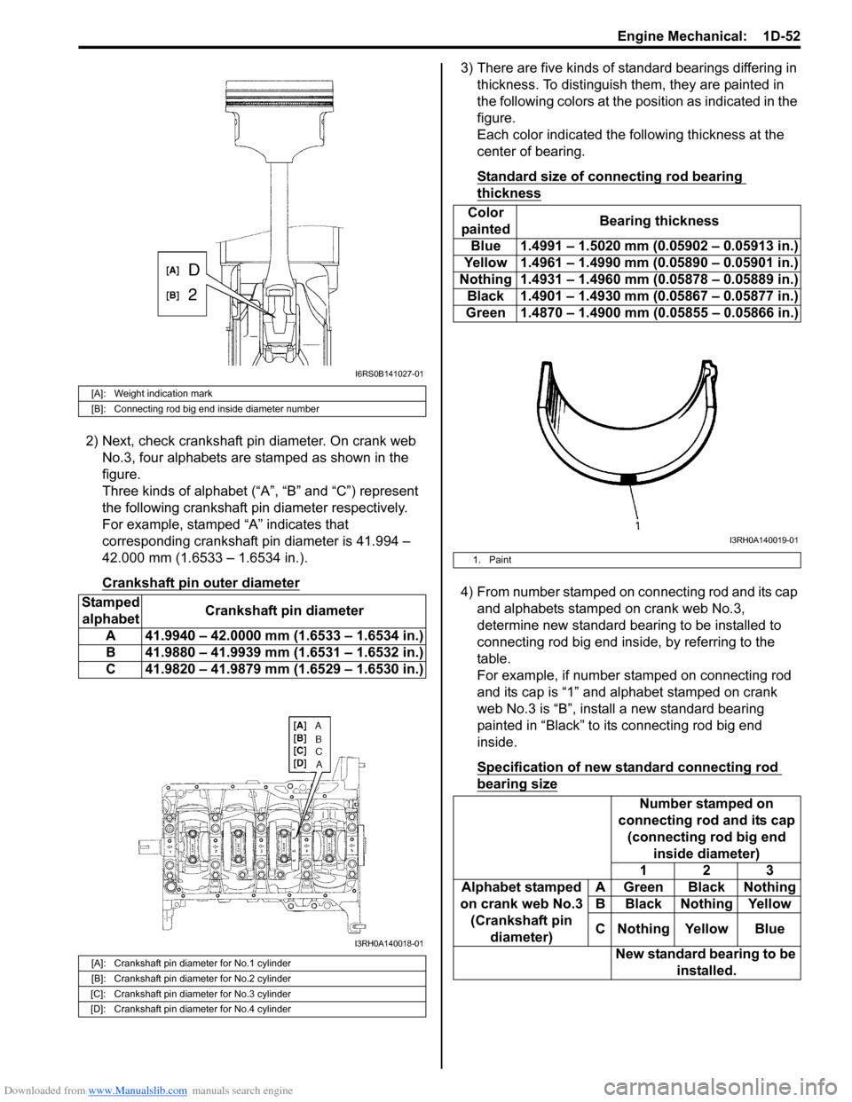
2) Next, check crankshaft pin diameter. On crank web No.3, four alphabets are stamped as shown in the
figure.
Three kinds of alphabet (“A”, “B” and “C”) represent
the following crankshaft pin diameter respectively.
For example, stamped “A” indicates that
corresponding crankshaft pin diameter is 41.994 –
42.000 mm (1.6533 – 1.6534 in.).
Crankshaft pin outer diameter
3) There are five kinds of standard bearings differing in thickness. To distinguish them, they are painted in
the following colors at the position as indicated in the
figure.
Each color indicated the following thickness at the
center of bearing.
Standard size of connecting rod bearing
thickness
4) From number stamped on connecting rod and its cap and alphabets stamped on crank web No.3,
determine new standard bearing to be installed to
connecting rod big end inside, by referring to the
table.
For example, if number stamped on connecting rod
and its cap is “1” and alphabet stamped on crank
web No.3 is “B”, install a new standard bearing
painted in “Black” to its connecting rod big end
inside.
Specification of new standard connecting rod
bearing size
[A]: Weight indication mark
[B]: Connecting rod big end inside diameter number
Stamped alphabet Crankshaft pin diameter
A 41.9940 – 42.0000 mm (1.6533 – 1.6534 in.)
B 41.9880 – 41.9939 mm (1.6531 – 1.6532 in.)
C 41.9820 – 41.9879 mm (1.6529 – 1.6530 in.)
[A]: Crankshaft pin diameter for No.1 cylinder
[B]: Crankshaft pin diameter for No.2 cylinder
[C]: Crankshaft pin diameter for No.3 cylinder
[D]: Crankshaft pin diameter for No.4 cylinder
I6RS0B141027-01
I3RH0A140018-01
Color
painted Bearing thickness
Blue 1.4991 – 1.5020 mm (0.05902 – 0.05913 in.)
Yellow 1.4961 – 1.4990 mm (0.05890 – 0.05901 in.)
Nothing 1.4931 – 1.4960 mm (0.05878 – 0.05889 in.) Black 1.4901 – 1.4930 mm (0.05867 – 0.05877 in.)
Green 1.4870 – 1.4900 mm (0.05855 – 0.05866 in.)
1. Paint
Number stamped on
connecting rod and its cap (connecting rod big end inside diameter)
123
Alphabet stamped
on crank web No.3 (Crankshaft pin diameter) A Green Black Nothing
B Black Nothing Yellow
C Nothing Yellow Blue
New standard bearing to be installed.
I3RH0A140019-01
Page 340 of 1496
Downloaded from www.Manualslib.com manuals search engine 1D-55 Engine Mechanical:
Installation
NOTE
• Use new bearing cap No.1 bolts. They are deformed once they are used because they
are plastic deformation tightening bolts.
• All parts to be insta lled must be perfectly
clean.
• Be sure to oil crankshaft journals, journal bearings, thrust bearings, crankpins,
connecting rod bearings, pistons, piston
rings and cylinder bores.
• Journal bearings, bearing caps, connecting rods, rod bearings, rod bearing
caps, pistons and piston rings are in
combination sets. Do not disturb such
combination and make sure that each part
goes back to where it came from, when
installing.
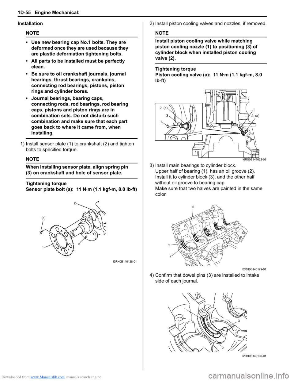
1) Install sensor plate (1) to crankshaft (2) and tighten bolts to spec ified torque.
NOTE
When installing sensor plate, align spring pin
(3) on crankshaft and hole of sensor plate.
Tightening torque
Sensor plate bolt (a): 11 N·m (1.1 kgf-m, 8.0 lb-ft) 2) Install piston cooling valves and nozzles, if removed.
NOTE
Install piston cooling valve while matching
piston cooling nozzle (1) to positioning (3) of
cylinder block when installed piston cooling
valve (2).
Tightening torque
Piston cooling valve (a): 11 N·m (1.1 kgf-m, 8.0
lb-ft)
3) Install main bearings to cylinder block. Upper half of bearing (1), has an oil groove (2).
Install it to cylinder block (3), and the other half
without oil groove to bearing cap.
Make sure that two halves are painted in the same
color.
4) Confirm that dowel pins (3 ) are installed to intake
side of each journal.
I2RH0B140128-01
I6RS0B141022-02
I2RH0B140129-01
I2RH0B140130-01
Page 342 of 1496
Downloaded from www.Manualslib.com manuals search engine 1D-57 Engine Mechanical:
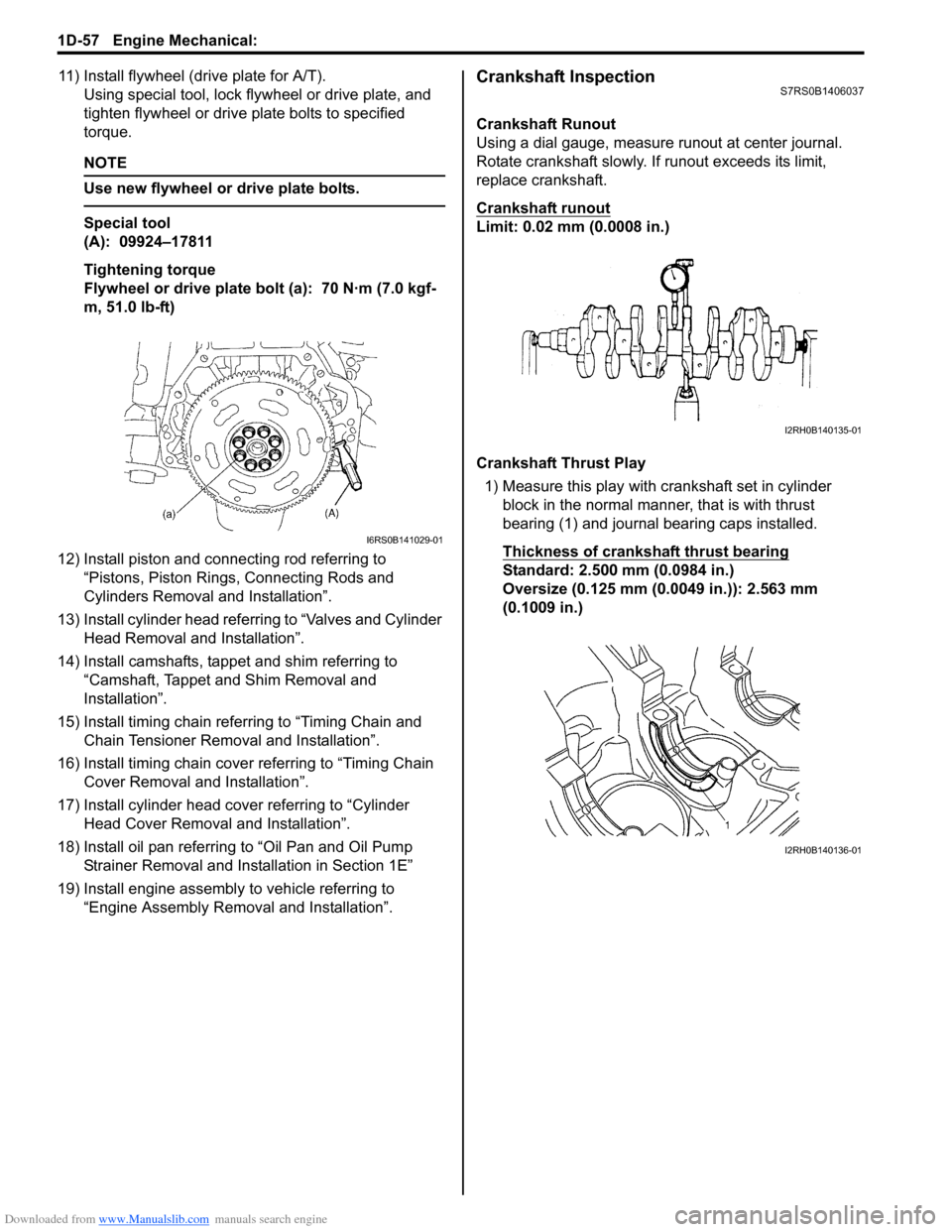
11) Install flywheel (drive plate for A/T).Using special tool, lock flyw heel or drive plate, and
tighten flywheel or drive plate bolts to specified
torque.
NOTE
Use new flywheel or drive plate bolts.
Special tool
(A): 09924–17811
Tightening torque
Flywheel or drive plate bolt (a): 70 N·m (7.0 kgf-
m, 51.0 lb-ft)
12) Install piston and connecting rod referring to “Pistons, Piston Rings, Connecting Rods and
Cylinders Removal and Installation”.
13) Install cylinder head referring to “Valves and Cylinder Head Removal and Installation”.
14) Install camshafts, tappet and shim referring to “Camshaft, Tappet and Shim Removal and
Installation”.
15) Install timing chain referring to “Timing Chain and Chain Tensioner Removal and Installation”.
16) Install timing chain cover referring to “Timing Chain Cover Removal and Installation”.
17) Install cylinder head cover referring to “Cylinder Head Cover Removal and Installation”.
18) Install oil pan referring to “Oil Pan and Oil Pump
Strainer Removal and Installation in Section 1E”
19) Install engine assembly to vehicle referring to “Engine Assembly Removal and Installation”.
Crankshaft InspectionS7RS0B1406037
Crankshaft Runout
Using a dial gauge, measure runout at center journal.
Rotate crankshaft slowly. If runout exceeds its limit,
replace crankshaft.
Crankshaft runout
Limit: 0.02 mm (0.0008 in.)
Crankshaft Thrust Play
1) Measure this play with crankshaft set in cylinder block in the normal manner, that is with thrust
bearing (1) and journal bearing caps installed.
Thickness of crankshaft thrust bearing
Standard: 2.500 mm (0.0984 in.)
Oversize (0.125 mm (0.0049 in.)): 2.563 mm
(0.1009 in.)
I6RS0B141029-01
I2RH0B140135-01
I2RH0B140136-01
Page 487 of 1496
Downloaded from www.Manualslib.com manuals search engine Drive Shaft / Axle: 3A-9
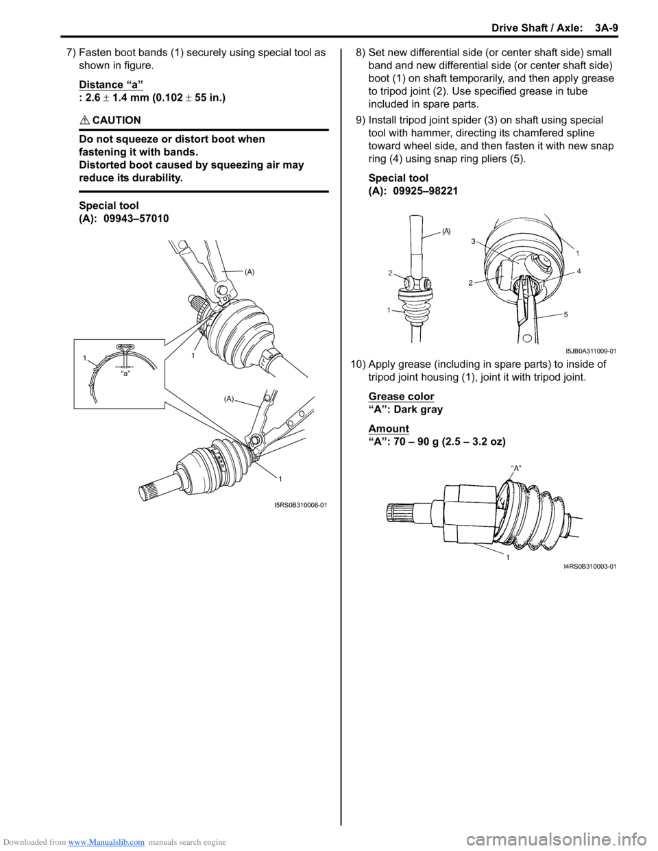
7) Fasten boot bands (1) securely using special tool as
shown in figure.
Distance “a”
: 2.6 ± 1.4 mm (0.102 ± 55 in.)
CAUTION!
Do not squeeze or distort boot when
fastening it with bands.
Distorted boot caused by squeezing air may
reduce its durability.
Special tool
(A): 09943–57010 8) Set new differential side (or center shaft side) small
band and new differential side (or center shaft side)
boot (1) on shaft temporarily, and then apply grease
to tripod joint (2). Use specified grease in tube
included in spare parts.
9) Install tripod joint spider (3) on shaft using special
tool with hammer, directing its chamfered spline
toward wheel side, and then fasten it with new snap
ring (4) using snap ring pliers (5).
Special tool
(A): 09925–98221
10) Apply grease (including in spare parts) to inside of tripod joint housing (1), jo int it with tripod joint.
Grease color
“A”: Dark gray
Amount
“A”: 70 – 90 g (2.5 – 3.2 oz)
(A)
1
(A)
1
“a”
1
I5RS0B310008-01
I5JB0A311009-01
I4RS0B310003-01
Page 489 of 1496
Downloaded from www.Manualslib.com manuals search engine Drive Shaft / Axle: 3A-11
DOJ
Judging from abnormality noted before disassembly and
what is found through visual check of components parts
after disassembly, prepare replacing parts and proceed
to reassembly.
Make sure that wheel side joint assembly and DOJ
housing are washed thoroughly and air dried.
Replace boot(s) with new one(s).
CAUTION!
• Do not wash boots in degreaser such as gasoline or kerosene. etc. Washing in
degreaser causes deterioration of boot.
• To ensure full performance of joint as designed, be sure to distinguish between
two types of grease in repair set and apply
specified volume to respective joint
referring to the followings for identification
of the grease.
1) Wash disassembled parts (except boots). After washing, dry parts completely by blowing air.
2) Clean boots with cloth.
3) Apply grease to wheel side joint. Use specified
grease in tube in wheel side boot set as a spare
parts.
Grease color
: Black
Amount
: 55 – 75 g (1.9 – 2.6 oz)
4) Install wheel side boot on shaft.
5) Fill up boot inside wi th specified grease.
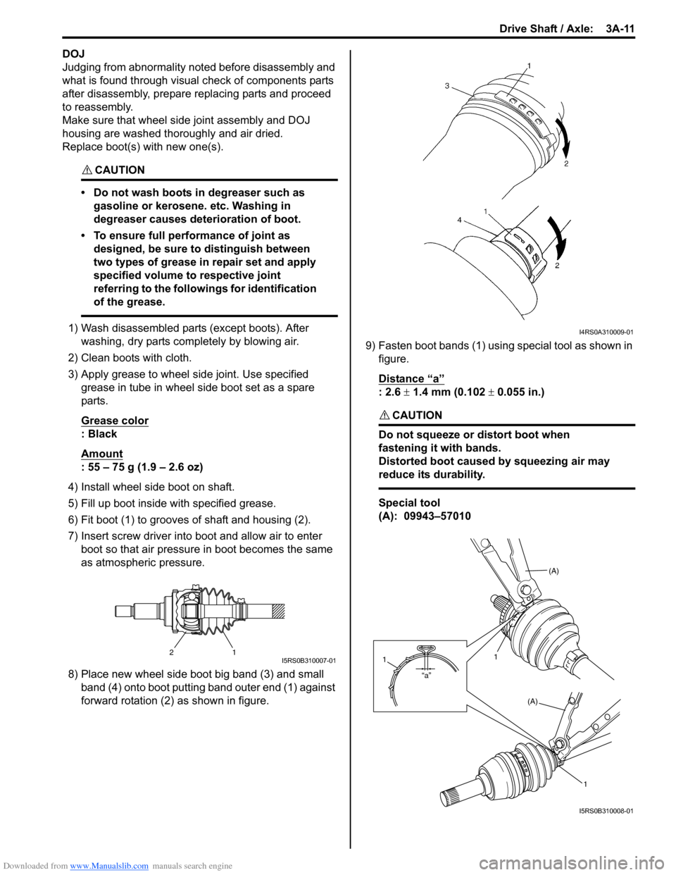
6) Fit boot (1) to grooves of shaft and housing (2).
7) Insert screw driver into boot and allow air to enter boot so that air pressure in boot becomes the same
as atmospheric pressure.
8) Place new wheel side boot big band (3) and small band (4) onto boot putting band outer end (1) against
forward rotation (2) as shown in figure. 9) Fasten boot bands (1) using special tool as shown in
figure.
Distance “a”
: 2.6 ± 1.4 mm (0.102 ± 0.055 in.)
CAUTION!
Do not squeeze or distort boot when
fastening it with bands.
Distorted boot caused by squeezing air may
reduce its durability.
Special tool
(A): 09943–57010
21I5RS0B310007-01
I4RS0A310009-01
(A)
1
(A)
1
“a”
1
I5RS0B310008-01
Page 491 of 1496

Downloaded from www.Manualslib.com manuals search engine Drive Shaft / Axle: 3A-13
18) Place differential side boot (or center shaft side) new
big band (3) and new small band (4) onto boot
putting band outer end (1) against forward rotation
(2) as shown in figure.
19) Fasten differential side (or center shaft side) boot band.
• For differential side (or center shaft side) boot big band
Fasten band (1) by drawing hooks (2) with special
tool and engage hooks (3) in slot and window (4).
Special tool
(A): 09943–57021
• For differential side (or center shaft side) boot small band
Fasten band (5) using special tool as shown in
figure.
Distance “a”
: 2.6 ± 1.4 mm (0.102 ± 0.055 in.)
Special tool
(B): 09943–57010
I5JB0A311006-01
(A)
1 4
2 3
(B)
5 “a”
I5RS0B310013-01