2007 SUZUKI SWIFT Assembled head
[x] Cancel search: Assembled headPage 319 of 1496

Downloaded from www.Manualslib.com manuals search engine Engine Mechanical: 1D-34
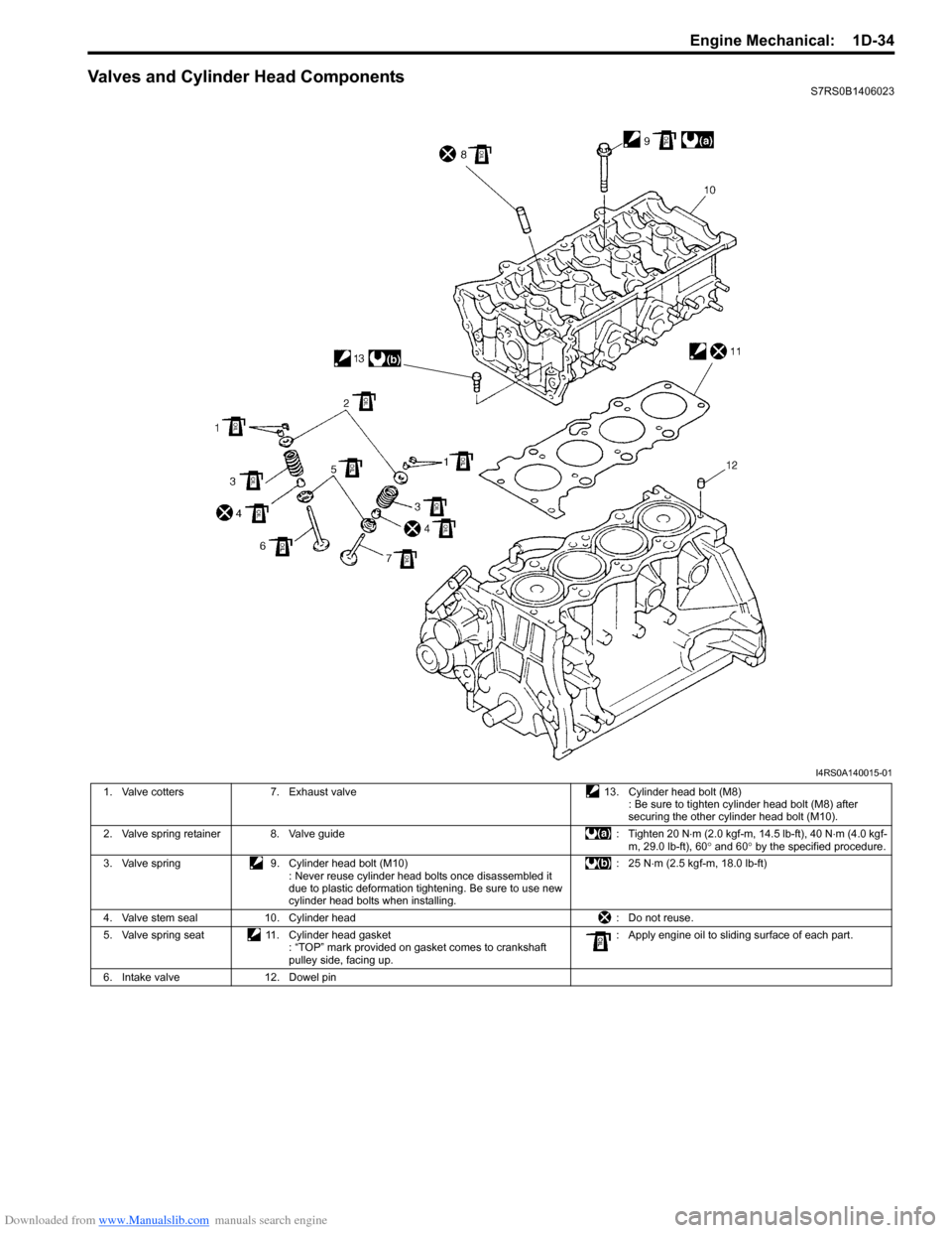
Valves and Cylinder Head ComponentsS7RS0B1406023
I4RS0A140015-01
1. Valve cotters7. Exhaust valve 13. Cylinder head bolt (M8)
: Be sure to tighten cylinder head bolt (M8) after
securing the other cylinder head bolt (M10).
2. Valve spring retainer 8. Valve guide : Tighten 20 N⋅m (2.0 kgf-m, 14.5 lb-ft), 40 N ⋅m (4.0 kgf-
m, 29.0 lb-ft), 60 ° and 60 ° by the specified procedure.
3. Valve spring 9. Cylinder head bolt (M10)
: Never reuse cylinder head bolts once disassembled it
due to plastic deformation tightening. Be sure to use new
cylinder head bolts when installing. : 25 N
⋅m (2.5 kgf-m, 18.0 lb-ft)
4. Valve stem seal 10. Cylinder head : Do not reuse.
5. Valve spring seat 11. Cylinder head gasket
: “TOP” mark provided on gasket comes to crankshaft
pulley side, facing up. : Apply engine oil to sliding surface of each part.
6. Intake valve 12. Dowel pin
Page 320 of 1496

Downloaded from www.Manualslib.com manuals search engine 1D-35 Engine Mechanical:
Valves and Cylinder Head Removal and
Installation
S7RS0B1406024
Removal1) Remove engine assembly from vehicle referring to “Engine Assembly Removal and Installation”.
2) Remove oil pan referring to “Oil Pan and Oil Pump
Strainer Removal and Installation in Section 1E”.
3) Remove cylinder head cover referring to “Cylinder Head Cover Removal and Installation”.
4) Remove timing chain cover referring to Steps 2) to 11) of “Removal” in “Tim ing Chain Cover Removal
and Installation”.
5) Remove timing chain referring to Steps 2) to 6) of “Removal” in “Timing Chain and Chain Tensioner
Removal and Installation”.
6) Remove intake and exhaust camshafts referring to Steps 3) to 8) of “Removal” in “Camshaft, Tappet and
Shim Removal and Installation”.
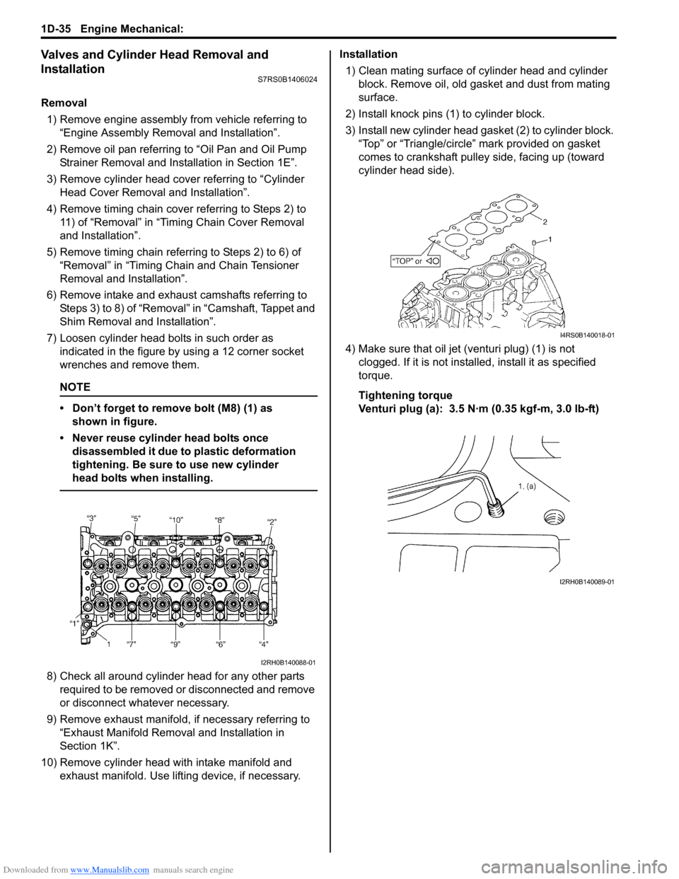
7) Loosen cylinder head bolts in such order as indicated in the figure by using a 12 corner socket
wrenches and remove them.
NOTE
• Don’t forget to remove bolt (M8) (1) as shown in figure.
• Never reuse cylinder head bolts once disassembled it due to plastic deformation
tightening. Be sure to use new cylinder
head bolts when installing.
8) Check all around cylinder head for any other parts required to be removed or disconnected and remove
or disconnect whatever necessary.
9) Remove exhaust manifold, if necessary referring to
“Exhaust Manifold Removal and Installation in
Section 1K”.
10) Remove cylinder head wi th intake manifold and
exhaust manifold. Use lifting device, if necessary. Installation
1) Clean mating surface of cylinder head and cylinder block. Remove oil, old gasket and dust from mating
surface.
2) Install knock pins (1) to cylinder block.
3) Install new cylinder head gasket (2) to cylinder block. “Top” or “Triangle/circle” mark provided on gasket
comes to crankshaft pulley side, facing up (toward
cylinder head side).
4) Make sure that oil jet (venturi plug) (1) is not clogged. If it is not install ed, install it as specified
torque.
Tightening torque
Venturi plug (a): 3.5 N·m (0.35 kgf-m, 3.0 lb-ft)
I2RH0B140088-01
I4RS0B140018-01
I2RH0B140089-01
Page 322 of 1496

Downloaded from www.Manualslib.com manuals search engine 1D-37 Engine Mechanical:
Valves and Cylinder Head Disassembly and
Assembly
S7RS0B1406025
Disassembly1) For ease in servicing cylinder head, remove intake manifold, injectors, exhaust manifold from cylinder
head.
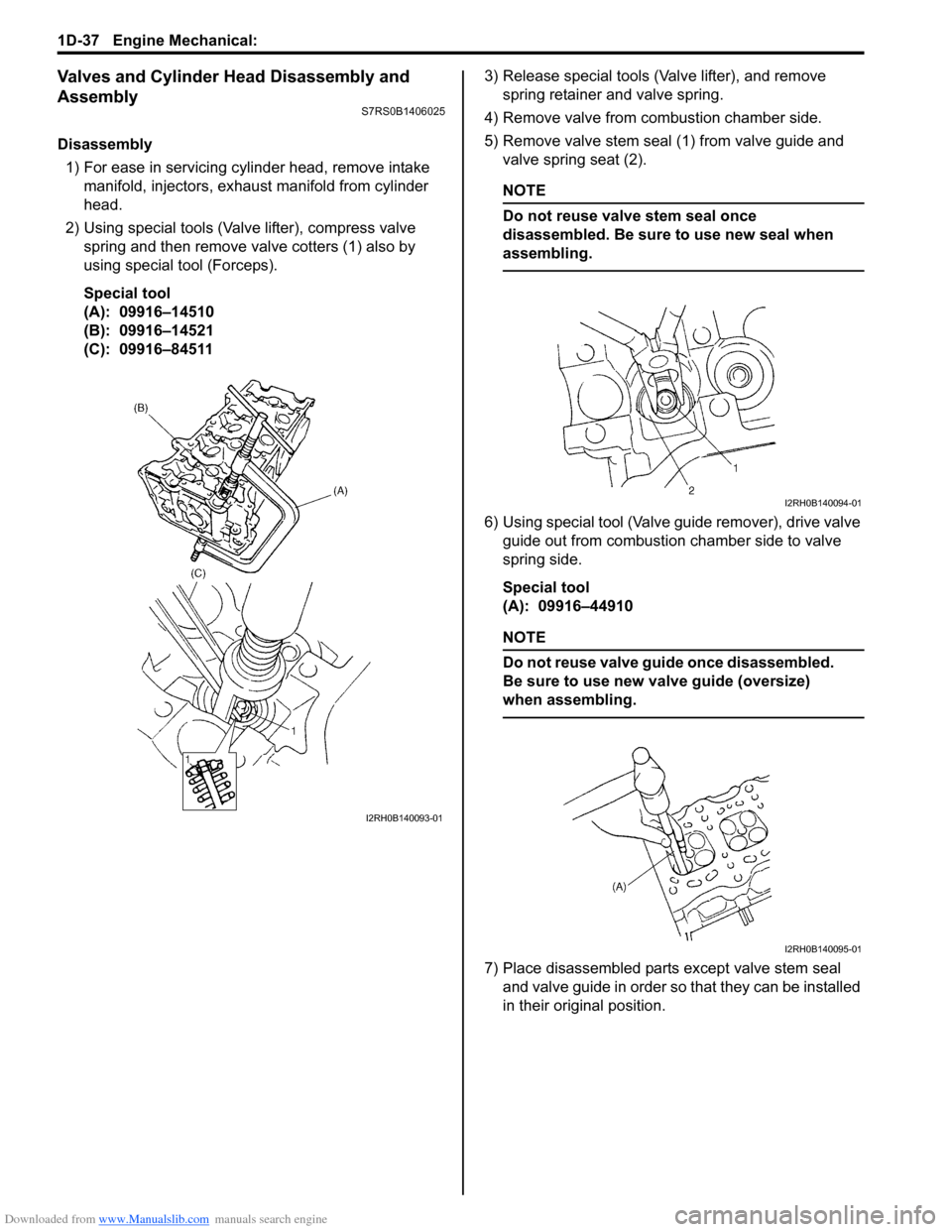
2) Using special tools (Val ve lifter), compress valve
spring and then remove valve cotters (1) also by
using special tool (Forceps).
Special tool
(A): 09916–14510
(B): 09916–14521
(C): 09916–84511 3) Release special tools (Valve lifter), and remove
spring retainer and valve spring.
4) Remove valve from combustion chamber side.
5) Remove valve stem seal (1) from valve guide and valve spring seat (2).
NOTE
Do not reuse valve stem seal once
disassembled. Be sure to use new seal when
assembling.
6) Using special tool (Valve guide remover), drive valve guide out from combustion chamber side to valve
spring side.
Special tool
(A): 09916–44910
NOTE
Do not reuse valve guide once disassembled.
Be sure to use new va lve guide (oversize)
when assembling.
7) Place disassembled parts except valve stem seal
and valve guide in order so that they can be installed
in their original position.
I2RH0B140093-01
I2RH0B140094-01
I2RH0B140095-01
Page 323 of 1496

Downloaded from www.Manualslib.com manuals search engine Engine Mechanical: 1D-38
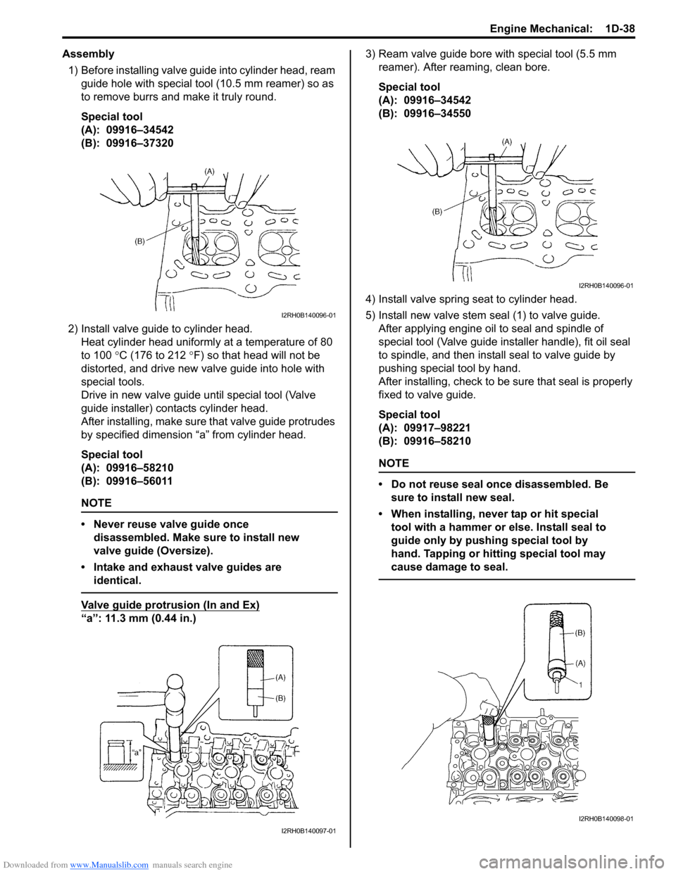
Assembly1) Before installing valve guide into cylinder head, ream
guide hole with special tool (10.5 mm reamer) so as
to remove burrs and make it truly round.
Special tool
(A): 09916–34542
(B): 09916–37320
2) Install valve guide to cylinder head. Heat cylinder head uniformly at a temperature of 80
to 100 °C (176 to 212 °F) so that head will not be
distorted, and drive new valve guide into hole with
special tools.
Drive in new valve guide until special tool (Valve
guide installer) contacts cylinder head.
After installing, ma ke sure that valve guide pr otrudes
by specified dimension “a” from cylinder head.
Special tool
(A): 09916–58210
(B): 09916–56011
NOTE
• Never reuse valve guide once disassembled. Make sure to install new
valve guide (Oversize).
• Intake and exhaust valve guides are identical.
Valve guide protrusion (In and Ex)
“a”: 11.3 mm (0.44 in.) 3) Ream valve guide bore with special tool (5.5 mm
reamer). After reaming, clean bore.
Special tool
(A): 09916–34542
(B): 09916–34550
4) Install valve spring seat to cylinder head.
5) Install new valve stem seal (1) to valve guide. After applying engine oil to seal and spindle of
special tool (Valve guide installer handle), fit oil seal
to spindle, and then install seal to valve guide by
pushing special tool by hand.
After installing, check to be sure that seal is properly
fixed to valve guide.
Special tool
(A): 09917–98221
(B): 09916–58210
NOTE
• Do not reuse seal once disassembled. Be sure to install new seal.
• When installing, never tap or hit special tool with a hammer or else. Install seal to
guide only by pushing special tool by
hand. Tapping or hitting special tool may
cause damage to seal.
I2RH0B140096-01
I2RH0B140097-01
I2RH0B140096-01
I2RH0B140098-01
Page 452 of 1496

Downloaded from www.Manualslib.com manuals search engine 2B-19 Front Suspension:
13) Install suspension control arm referring to
“Suspension Control Arm / Bushing Removal and
Installation”.
14) Connect couplers of torque sensor and P/S motor.
15) Connect tie-rod ends to knuckles (right & left) and then install cotter pins referring to “Tie-Rod End
Removal and Installa tion in Section 6C”.
16) Be sure that steering wheel and brake discs (right & left) are all straight-ahead position and then insert
steering lower shaft (5) into steering pinion shaft (3)
with matching marks (4).
17) Tighten steering shaft joint lower bolt (1) and upper bolt (2) to specified torque (Lower side first and then
upper side).
Tightening torque
Steering shaft joint bolt (a): 25 N·m (2.5 kgf-m,
18.5 lb-ft)
18) Install both wheels and tighten wheel bolts to specified torque.
Tightening torque
Wheel bolt: 85 N·m (8.5 kgf-m, 61.5 lb-ft)
19) Lower hoist.
20) Check toe setting. Adjust as required refer to “Front Wheel Alignment Inspection and Adjustment”.
Front Suspension Frame CheckS7RS0B2206016
Inspect for cracks, deformation or damage.
If defective, replace.
Front Stabilizer Bar, Bushing and/or Joint
Check
S7RS0B2206017
Stabilizer Bar
Inspect for damage or deformation.
If defective, replace.
Stabilizer Bushing
Inspect for damage, wear or deterioration.
If defective, replace.
Stabilizer Joint
1) Check for smooth rotation.
2) Check damages of ball stud.
3) Check damages of dust cover.
NOTE
Stabilizer joint (1) cannot be disassembled.
If there is any damage to either parts, stabilizer joint
assembly must be replaced as a complete unit.
Front Suspension Fasteners CheckS7RS0B2206018
Check each bolt and nut fastening suspension parts for
tightness. Tighten loose one, if any, to specified torque,
referring to “Front Suspension Construction”.
5
4
1, (a)
3
2, (a)
1, (a)
5
I4RS0B630016-01
I4RS0A220054-01
I4RS0A220052-01
I4RS0A220056-01
1
I4RH01220007-01