2007 SUZUKI SWIFT ecm input
[x] Cancel search: ecm inputPage 209 of 1496
Downloaded from www.Manualslib.com manuals search engine Engine General Information and Diagnosis: 1A-159
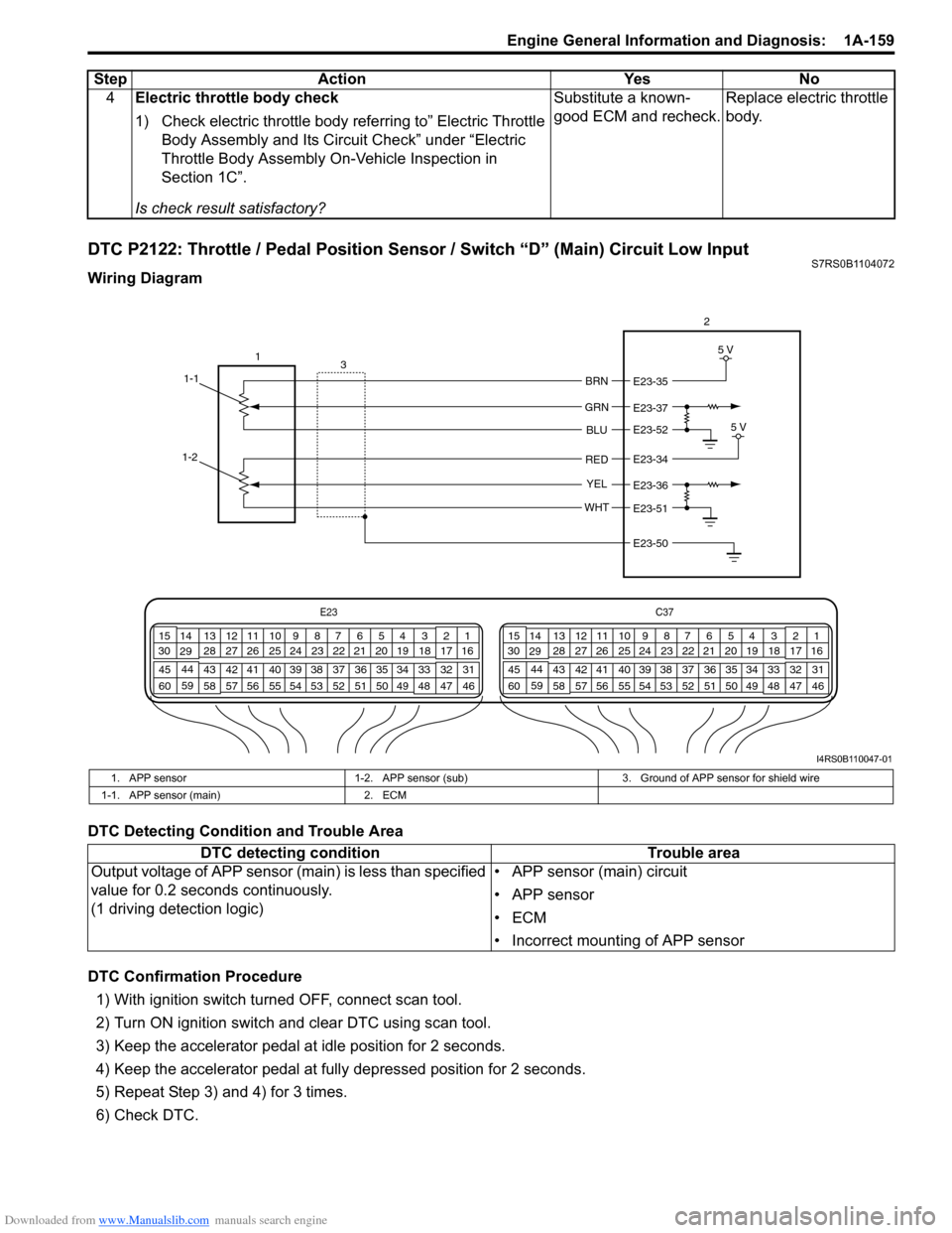
DTC P2122: Throttle / Pedal Position Sensor / Switch “D” (Main) Circuit Low InputS7RS0B1104072
Wiring Diagram
DTC Detecting Condition and Trouble Area
DTC Confirmation Procedure1) With ignition switch turned OFF, connect scan tool.
2) Turn ON ignition switch and clear DTC using scan tool.
3) Keep the accelerator pedal at idle position for 2 seconds.
4) Keep the accelerator pedal at fully depressed position for 2 seconds.
5) Repeat Step 3) and 4) for 3 times.
6) Check DTC. 4
Electric throttle body check
1) Check electric throttle body referring to” Electric Throttle
Body Assembly and Its Circuit Check” under “Electric
Throttle Body Assembly On-Vehicle Inspection in
Section 1C”.
Is check result satisfactory? Substitute a known-
good ECM and recheck.
Replace electric throttle
body.
Step Action Yes No
E23
C37
34
1819
567
1011
17
20
47 46
495051
2122
52 16
25 9
24
14
29
55
57 54 53
59
60 58 2
262728
15
30
56 4832 31
34353637
40
42 39 38
44
45 43 41 331
1213
238
34
1819
567
1011
17
20
47 46
495051
2122
52 16
25 9
24
14
29
55
57 54 53
59
60 58 2
262728
15
30
56 48 32 31
34353637
40
42 39 38
44
45 43 41 331
1213
238
BRN
GRN
BLU
RED
YEL
WHT
E23-35
E23-37
E23-52
E23-34
E23-36
E23-51
E23-50 5 V
5 V
1
1-1 3 2
1-2
I4RS0B110047-01
1. APP sensor
1-2. APP sensor (sub) 3. Ground of APP sensor for shield wire
1-1. APP sensor (main) 2. ECM
DTC detecting condition Trouble area
Output voltage of APP sensor (main) is less than specified
value for 0.2 seconds continuously.
(1 driving detection logic) • APP sensor (main) circuit
• APP sensor
•ECM
• Incorrect mounting of APP sensor
Page 211 of 1496
Downloaded from www.Manualslib.com manuals search engine Engine General Information and Diagnosis: 1A-161
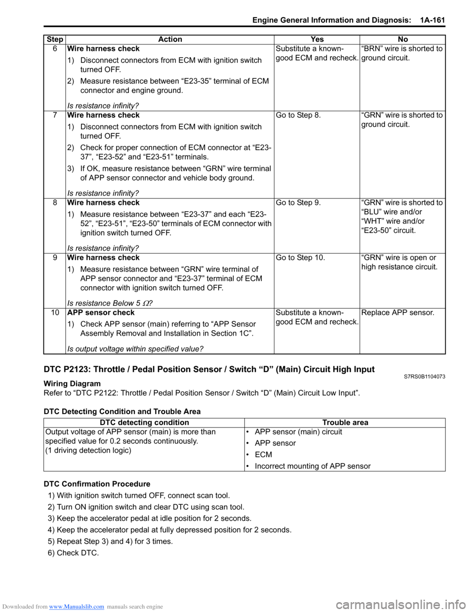
DTC P2123: Throttle / Pedal Position Sensor / Switch “D” (Main) Circuit High InputS7RS0B1104073
Wiring Diagram
Refer to “DTC P2122: Throttle / Pedal Position Sensor / Switch “D” (Main) Circuit Low Input”.
DTC Detecting Condition and Trouble Area
DTC Confirmation Procedure 1) With ignition switch turned OFF, connect scan tool.
2) Turn ON ignition switch and clear DTC using scan tool.
3) Keep the accelerator pedal at idle position for 2 seconds.
4) Keep the accelerator pedal at fully depressed position for 2 seconds.
5) Repeat Step 3) and 4) for 3 times.
6) Check DTC. 6
Wire harness check
1) Disconnect connectors from ECM with ignition switch
turned OFF.
2) Measure resistance between “E23-35” terminal of ECM connector and engine ground.
Is resistance infinity? Substitute a known-
good ECM and recheck.
“BRN” wire is shorted to
ground circuit.
7 Wire harness check
1) Disconnect connectors from ECM with ignition switch
turned OFF.
2) Check for proper connection of ECM connector at “E23- 37”, “E23-52” and “E23-51” terminals.
3) If OK, measure resistance between “GRN” wire terminal of APP sensor connector and vehicle body ground.
Is resistance infinity? Go to Step 8. “GRN” wire is shorted to
ground circuit.
8 Wire harness check
1) Measure resistance between “E23-37” and each “E23-
52”, “E23-51”, “E23-50” terminals of ECM connector with
ignition switch turned OFF.
Is resistance infinity? Go to Step 9. “GRN” wire is shorted to
“BLU” wire and/or
“WHT” wire and/or
“E23-50” circuit.
9 Wire harness check
1) Measure resistance between “GRN” wire terminal of
APP sensor connector and “E23-37” terminal of ECM
connector with ignition switch turned OFF.
Is resistance Below 5
Ω? Go to Step 10. “GRN” wire is open or
high resistance circuit.
10 APP sensor check
1) Check APP sensor (main) re ferring to “APP Sensor
Assembly Removal and Inst allation in Section 1C”.
Is output voltage within specified value? Substitute a known-
good ECM and recheck.
Replace APP sensor.
Step Action Yes No
DTC detecting condition
Trouble area
Output voltage of APP sensor (main) is more than
specified value for 0.2 seconds continuously.
(1 driving detection logic) • APP sensor (main) circuit
• APP sensor
•ECM
• Incorrect mounting of APP sensor
Page 214 of 1496
Downloaded from www.Manualslib.com manuals search engine 1A-164 Engine General Information and Diagnosis:
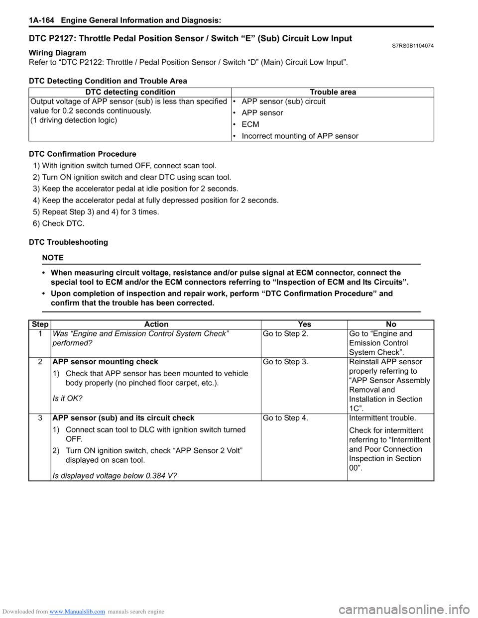
DTC P2127: Throttle Pedal Position Sensor / Switch “E” (Sub) Circuit Low InputS7RS0B1104074
Wiring Diagram
Refer to “DTC P2122: Throttle / Pedal Position Sensor / Switch “D” (Main) Circuit Low Input”.
DTC Detecting Condition and Trouble Area
DTC Confirmation Procedure 1) With ignition switch turned OFF, connect scan tool.
2) Turn ON ignition switch and clear DTC using scan tool.
3) Keep the accelerator pedal at idle position for 2 seconds.
4) Keep the accelerator pedal at fully depressed position for 2 seconds.
5) Repeat Step 3) and 4) for 3 times.
6) Check DTC.
DTC Troubleshooting
NOTE
• When measuring circuit voltage, resistance and/ or pulse signal at ECM connector, connect the
special tool to ECM and/or the ECM connectors re ferring to “Inspection of ECM and Its Circuits”.
• Upon completion of inspection and repair work, perform “DTC Confirmation Procedure” and confirm that the trouble has been corrected.
DTC detecting condition Trouble area
Output voltage of APP sensor (sub) is less than specified
value for 0.2 seconds continuously.
(1 driving detection logic) • APP sensor (sub) circuit
• APP sensor
•ECM
• Incorrect mounting of APP sensor
Step
Action YesNo
1 Was “Engine and Emission Control System Check”
performed? Go to Step 2.
Go to “Engine and
Emission Control
System Check”.
2 APP sensor mounting check
1) Check that APP sensor has been mounted to vehicle
body properly (no pinched floor carpet, etc.).
Is it OK? Go to Step 3.
Reinstall APP sensor
properly referring to
“APP Sensor Assembly
Removal and
Installation in Section
1C”.
3 APP sensor (sub) and its circuit check
1) Connect scan tool to DLC with ignition switch turned
OFF.
2) Turn ON ignition switch, check “APP Sensor 2 Volt” displayed on scan tool.
Is displayed voltage below 0.384 V? Go to Step 4.
Intermittent trouble.
Check for intermittent
referring to “Intermittent
and Poor Connection
Inspection in Section
00”.
Page 216 of 1496
Downloaded from www.Manualslib.com manuals search engine 1A-166 Engine General Information and Diagnosis:
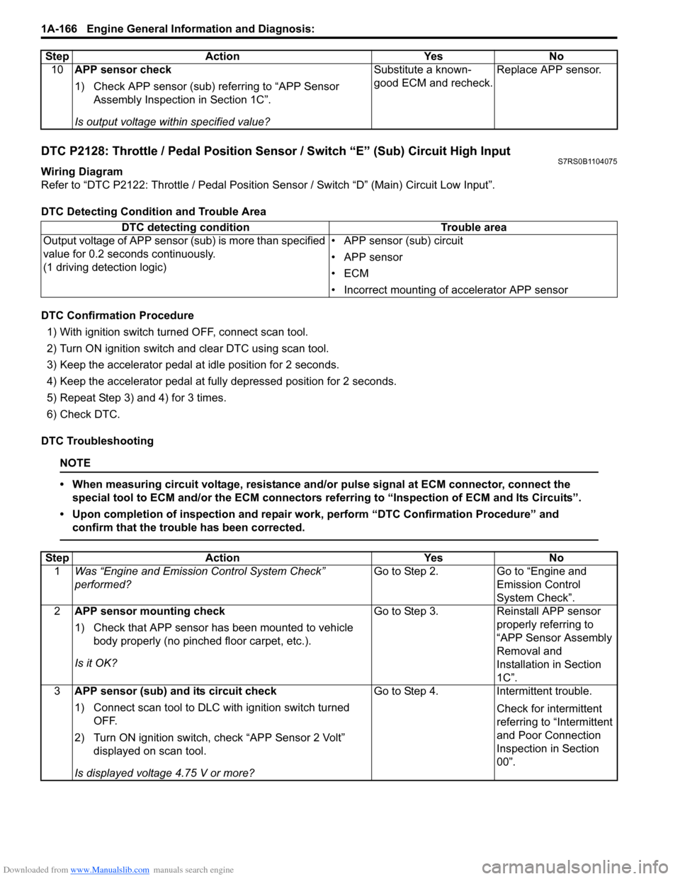
DTC P2128: Throttle / Pedal Position Sensor / Switch “E” (Sub) Circuit High InputS7RS0B1104075
Wiring Diagram
Refer to “DTC P2122: Throttle / Pedal Position Sensor / Switch “D” (Main) Circuit Low Input”.
DTC Detecting Condition and Trouble Area
DTC Confirmation Procedure 1) With ignition switch turned OFF, connect scan tool.
2) Turn ON ignition switch and clear DTC using scan tool.
3) Keep the accelerator pedal at idle position for 2 seconds.
4) Keep the accelerator pedal at fully depressed position for 2 seconds.
5) Repeat Step 3) and 4) for 3 times.
6) Check DTC.
DTC Troubleshooting
NOTE
• When measuring circuit voltage, resistance and/ or pulse signal at ECM connector, connect the
special tool to ECM and/or the ECM connectors re ferring to “Inspection of ECM and Its Circuits”.
• Upon completion of inspection and repair work, perform “DTC Confirmation Procedure” and confirm that the trouble has been corrected.
10 APP sensor check
1) Check APP sensor (sub) re ferring to “APP Sensor
Assembly Inspection in Section 1C”.
Is output voltage within specified value? Substitute a known-
good ECM and recheck.
Replace APP sensor.
Step Action Yes No
DTC detecting condition
Trouble area
Output voltage of APP sensor (s ub) is more than specified
value for 0.2 seconds continuously.
(1 driving detection logic) • APP sensor (sub) circuit
• APP sensor
•ECM
• Incorrect mounting of
accelerator APP sensor
Step Action YesNo
1 Was “Engine and Emission Control System Check”
performed? Go to Step 2.
Go to “Engine and
Emission Control
System Check”.
2 APP sensor mounting check
1) Check that APP sensor has been mounted to vehicle
body properly (no pinched floor carpet, etc.).
Is it OK? Go to Step 3.
Reinstall APP sensor
properly referring to
“APP Sensor Assembly
Removal and
Installation in Section
1C”.
3 APP sensor (sub) and its circuit check
1) Connect scan tool to DLC with ignition switch turned
OFF.
2) Turn ON ignition switch, check “APP Sensor 2 Volt” displayed on scan tool.
Is displayed voltage 4.75 V or more? Go to Step 4.
Intermittent trouble.
Check for intermittent
referring to “Intermittent
and Poor Connection
Inspection in Section
00”.
Page 224 of 1496

Downloaded from www.Manualslib.com manuals search engine 1A-174 Engine General Information and Diagnosis:
DTC Confirmation Procedure
DTC P2227:
WARNING!
• When performing a road test, select a place where there is no traffic or possibility of a traffic accident and be very careful during testing to avoid occurrence of an accident.
• Road test should be carried out by 2 persons, a driver and a tester, on a level road.
1) Connect scan tool to DLC with ignition switch turned OFF.
2) Turn ON ignition switch and clear DTC, pending DTC and freeze frame data by using scan tool and warm up
engine to normal operating temperature.
3) Check DTC and pending DTC by using scan tool.
DTC P2228 / P2229: 1) Connect scan tool to DLC with ignition switch turned OFF.
2) Turn ON ignition switch, clear DTC by using scan tool and run engine for 1 min.
3) Check DTC.
DTC Troubleshooting
NOTE
• When measuring circuit voltage, resistance and/ or pulse signal at ECM connector, connect the
special tool to ECM and/or the ECM connectors re ferring to “Inspection of ECM and Its Circuits”.
• Upon completion of inspection and repair work, perform “DTC Confirmation Procedure” and confirm that the trouble has been corrected.
Step Action YesNo
1 Was “Engine and Emission Control System Check”
performed? Go to Step 2.
Go to “Engine and
Emission Control
System Check”.
2 Is DTC P2227 set? Go to Step 3.Substitute a known-
good ECM and recheck.
3 MAP sensor check
1) Check MAP sensor and its circuit referring to “DTC
P0107: Manifold Absolute Pressure / Barometric
Pressure Circuit Low Input” and/or “DTC P0108:
Manifold Absolute Pressure / Barometric Pressure
Circuit High Input”.
Is check result satisfactory? Substitute a known-
good ECM and recheck.
MAP sensor or its circuit
malfunction.
Page 397 of 1496

Downloaded from www.Manualslib.com manuals search engine Ignition System: 1H-5
6Ignition coil assembly power supply and ground circuit
check
1) Check ignition coil assembly power supply and ground
circuits for open and short.
Are circuits in good condition? Go to Step 7.
Repair or replace.
7 Ignition coil assembly check
1) Check ignition coil for resistance referring to “Ignition
Coil Assembly (Including ignitor) Inspection”.
Is check result satisfactory? Go to Step 8.
Replace ignition coil
assembly.
8 CKP sensor check
1) Check CKP sensor referring to “CKP Sensor Inspection
in Section 1C”.
Is check result satisfactory? Go to Step 9.
Tighten CKP sensor
bolt, replace CKP
sensor or CKP sensor
plate.
9 CMP sensor check
1) Check CMP sensor referring to “Camshaft Position
(CMP) Sensor Inspection in Section 1C”.
Is check result satisfactory? Go to Step 10. Tighten CMP sensor
bolt, replace CMP
sensor or intake
camshaft.
10 Ignition trigger signal circuit check
1) Check ignition trigger signal wire for open, short and
poor connection.
Is circuit in good condition? Go to Step 11. Repair or replace.
11 A known-good ignition coil assembly substitution
1) Substitute a known-good ignition coil assembly and then
repeat Step 2.
Is check result of Step 2 satisfactory? Go to Step 12. Substitute a known-
good ECM and then
repeat Step 2.
12 Knock sensor check
1) Confirm that knock sensor circuit is in good condition
referring to “DTC P0327 / P0328: Knock Sensor 1 Circuit
Low / High in Section 1A”.
2) Check oscilloscope waveform of knock sensor signal
referring to “Reference waveform No.25” and
“Reference waveform No.26” under “Inspection of ECM
and Its Circuits in Section 1A”.
Is check result satisfactory? Go to Step 13. Substitute a known-
good knock sensor and
recheck.
13 Ignition timing check
1) Check initial ignition timing and ignition timing advance
referring to “Ignition Timing Inspection”.
Is check result satisfactory? System is in good
condition.
Check CMP sensor,
CMP sensor rotor tooth
of camshaft, CKP
sensor, CKP sensor
plate and/or input
signals related to this
system.
Step
Action YesNo
Page 543 of 1496
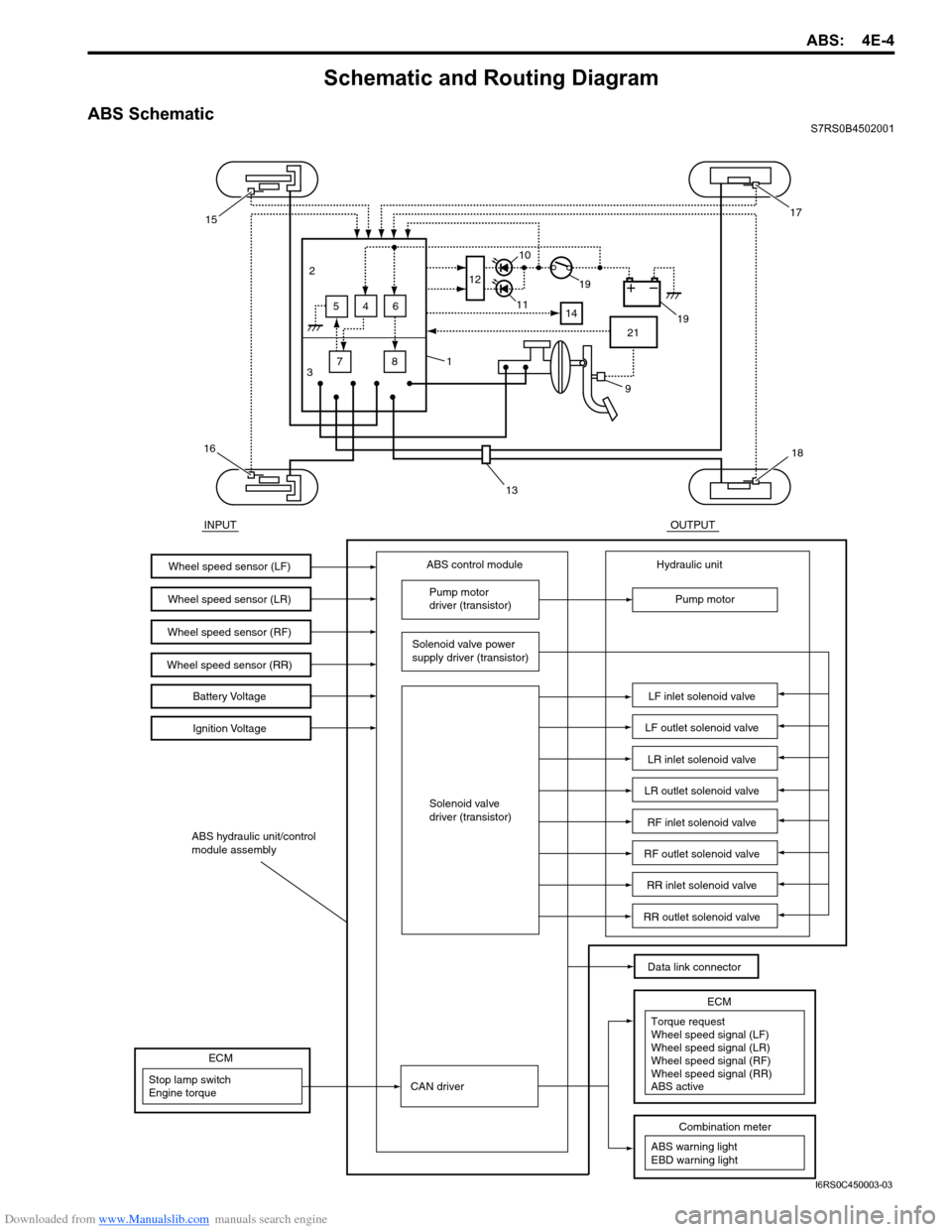
Downloaded from www.Manualslib.com manuals search engine ABS: 4E-4
Schematic and Routing Diagram
ABS SchematicS7RS0B4502001
INPUTOUTPUT
ABS control moduleWheel speed sensor (LF)
Wheel speed sensor (LR)
Wheel speed sensor (RF)Battery Voltage
Ignition Voltage
Pump motor
driver (transistor)
Solenoid valve power
supply driver (transistor)
Solenoid valve
driver (transistor) Hydraulic unit
Pump motor
LF inlet solenoid valve
LF outlet solenoid valve
LR inlet solenoid valve
LR outlet solenoid valve
RF inlet solenoid valve
RF outlet solenoid valve
RR inlet solenoid valve
RR outlet solenoid valve
Data link connector
ABS hydraulic unit/control
module assembly
Wheel speed sensor (RR)
3 7
2
645
8 12
14
21
15
16
1
13
18
17
19
19
11
10
9
CAN driverStop lamp switch
Engine torque
ECM
ABS warning light
EBD warning light
Combination meter
Torque request
ECMWheel speed signal (LF)
Wheel speed signal (LR)
Wheel speed signal (RF)
Wheel speed signal (RR)
ABS active
I6RS0C450003-03
Page 582 of 1496
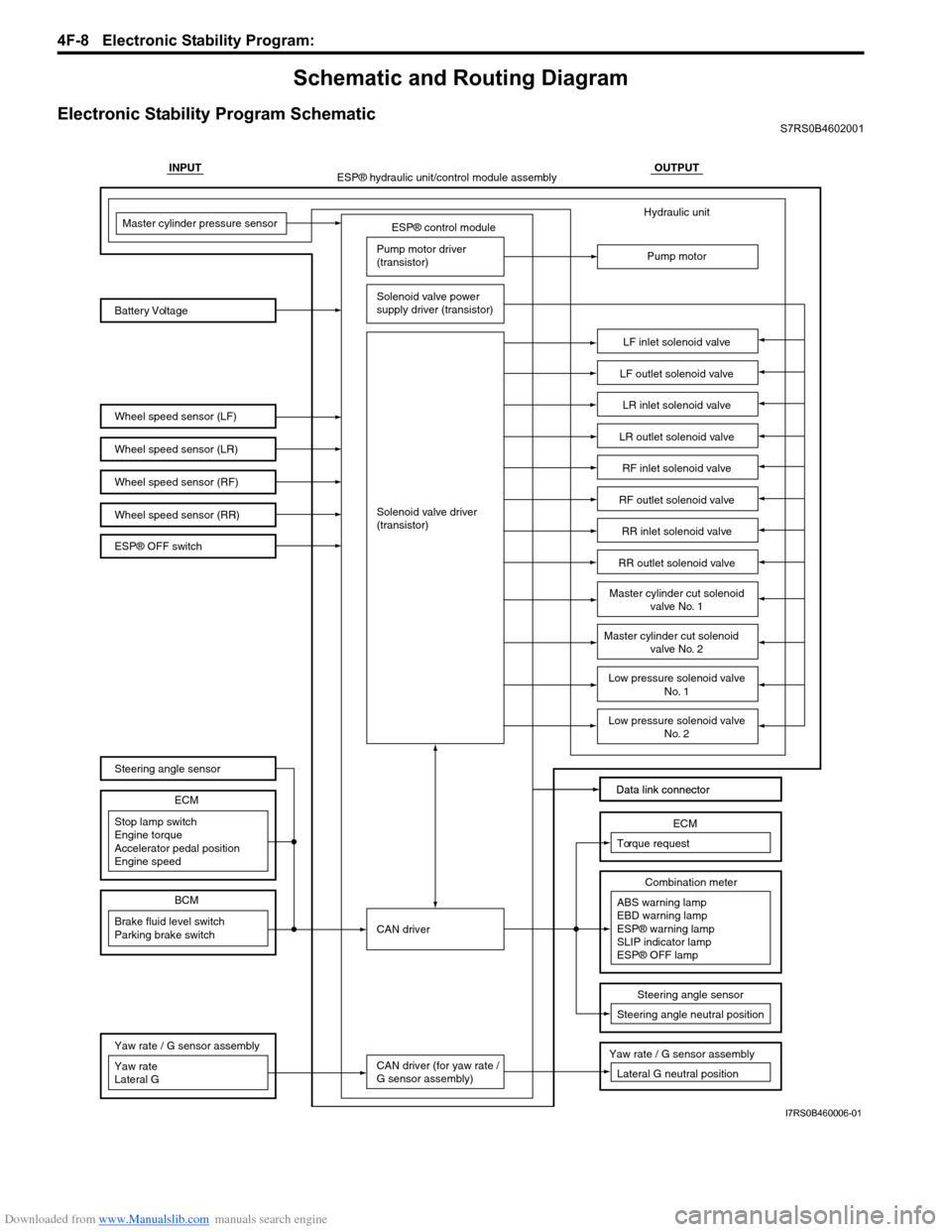
Downloaded from www.Manualslib.com manuals search engine 4F-8 Electronic Stability Program:
Schematic and Routing Diagram
Electronic Stability Program SchematicS7RS0B4602001
INPUTOUTPUT
ESP® control module
Wheel speed sensor (LF)
Wheel speed sensor (LR)
Wheel speed sensor (RF) Battery VoltageMaster cylinder pressure sensor
Pump motor driver
(transistor)
Solenoid valve power
supply driver (transistor)
Solenoid valve driver
(transistor)
CAN driver
CAN driver (for yaw rate /
G sensor assembly) Hydraulic unit
Pump motor
LF inlet solenoid valve
LF outlet solenoid valve
LR inlet solenoid valve
LR outlet solenoid valve
RF inlet solenoid valve
RF outlet solenoid valve
RR inlet solenoid valve
RR outlet solenoid valve
Data link connector
Data link connector
ESP® hydraulic unit/control module assembly
Wheel speed sensor (RR)
Master cylinder cut solenoid valve No. 1
Master cylinder cut solenoid
valve No. 2
Low pressure solenoid valve No. 1
Low pressure solenoid valveNo. 2
Stop lamp switch
Engine torque
Accelerator pedal position
Engine speed ECM
Brake fluid level switch
Parking brake switch
BCM
Steering angle sensor
ESP® OFF switch
Yaw rate
Lateral G Yaw rate / G sensor assembly
ABS warning lamp
EBD warning lamp
ESP® warning lamp
SLIP indicator lamp
ESP® OFF lampCombination meter
Torque request
ECM
Steering angle neutral positionSteering angle sensor
Yaw rate / G sensor assembly
Lateral G neutral position
I7RS0B460006-01