2007 SUZUKI SWIFT Door trim
[x] Cancel search: Door trimPage 4 of 1496

Downloaded from www.Manualslib.com manuals search engine 00
0
1
2
3
4
5
6
7
8
9
10
11
Vo l u m e 1
Precautions............................................................... 00-iPrecautions ............................................................ 00-1
General Information ................ ................................... 0-i
General Information ............................................... 0A-1
Maintenance and Lubricatio n ................................. 0B-1
Engine ......................................................................... 1-i Precautions .............................................................. 1-1
Engine General Information and Diagnosis ........... 1A-1
Aux. Emission Control Devices .............................. 1B-1
Engine Electrical Devices....................................... 1C-1
Engine Mechanical ................................................. 1D-1
Engine Lubrication System .................................... 1E-1
Engine Cooling System .......................................... 1F-1
Fuel System ...........................................................1G-1
Ignition System....................................................... 1H-1
Starting System ....................................................... 1I-1
Charging System.....................................................1J-1
Exhaust System ..................................................... 1K-1
Suspension ................................................................. 2-i Precautions .............................................................. 2-1
Suspension General Diagnosis .............................. 2A-1
Front Suspension ................................................... 2B-1
Rear Suspension................ .................................... 2C-1
Wheels and Tires ................................................... 2D-1
Driveline / Axle ........................................................... 3-i Precautions .............................................................. 3-1
Drive Shaft / Axle ................................................... 3A-1
Brakes ......................................................................... 4-i Precautions .............................................................. 4-1
Brake Control System and Diagnosis .................... 4A-1
Front Brakes........................................................... 4B-1
Rear Brakes ........................................................... 4C-1
Parking Brake......................................................... 4D-1
ABS ........................................................................ 4E-1
Electronic Stability Program ................................... 4F-1
Vo l u m e 2
Precautions ............................................................... 00-iPrecautions ............................................................ 00-1
Transmission / Transaxle .... ...................................... 5-i
Precautions .............................................................. 5-1
Automatic Transmission/Transaxle ........................ 5A-1
Manual Transmission/Transaxle ............................ 5B-1
Clutch .....................................................................5C-1
Steering ....................................................................... 6-i Precautions .............................................................. 6-1
Steering General Diagnosis ................................... 6A-1
Steering Wheel and Column .................................. 6B-1
Power Assisted Steering System ...........................6C-1
HVAC ........................................................................... 7-i Precautions .............................................................. 7-1
Heater and Ventilation............................................ 7A-1
Air Conditioning System ......................................... 7B-1
Restraint ...................................................................... 8-i Precautions .............................................................. 8-1
Seat Belts ............................................................... 8A-1
Air Bag System ...................................................... 8B-1
Body, Cab and Accessories .... .................................. 9-i
Precautions .............................................................. 9-1
Wiring Systems ...................................................... 9A-1
Lighting Systems .................................................... 9B-1
Instrumentation / Driver Info. / Horn .......................9C-1
Wipers / Washers ...................................................9D-1
Glass / Windows / Mirrors ...................................... 9E-1
Security and Locks ................................................. 9F-1
Seats ..................................................................... 9G-1
Interior Trim ............................................................9H-1
Hood / Fenders / Doors .......................................... 9J-1
Body Structure ....................................................... 9K-1
Paint / Coatings ...................................................... 9L-1
Exterior Trim .......................................................... 9M-1
Control Systems ....................................................... 10-i Precautions ............................................................ 10-1
Body Electrical Control Sy stem ............................ 10B-1
Immobilizer Control System .................................10C-1
Keyless Start System ........................................... 10E-1
TABLE OF CONTENTS
Page 1153 of 1496
Downloaded from www.Manualslib.com manuals search engine Air Bag System: 8B-115
WARNING!
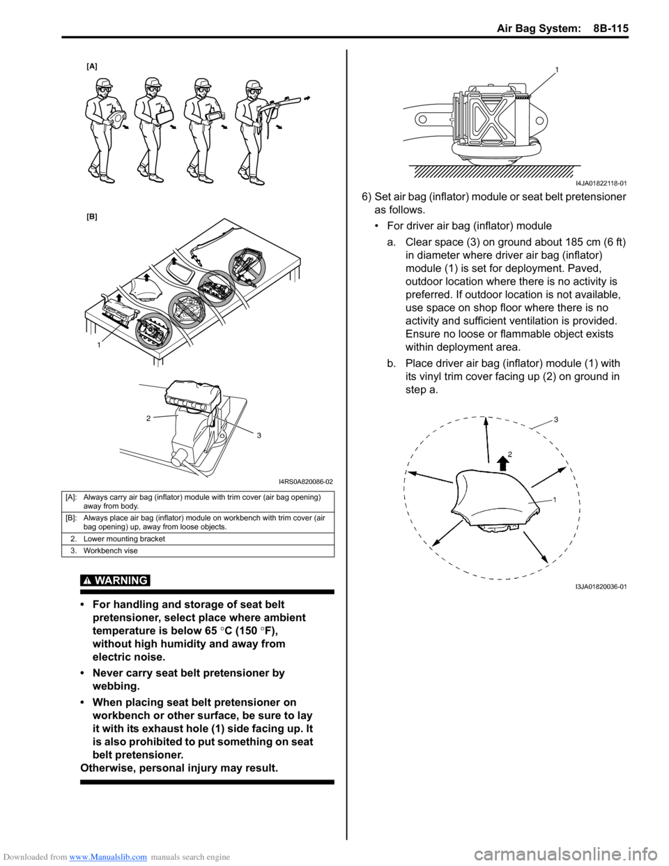
• For handling and storage of seat belt pretensioner, select place where ambient
temperature is below 65 °C (150 °F),
without high humidity and away from
electric noise.
• Never carry seat belt pretensioner by webbing.
• When placing seat belt pretensioner on workbench or other surface, be sure to lay
it with its exhaust hole (1) side facing up. It
is also prohibited to put something on seat
belt pretensioner.
Otherwise, personal injury may result.
6) Set air bag (inflator) module or seat belt pretensioner
as follows.
• For driver air bag (inflator) module
a. Clear space (3) on ground about 185 cm (6 ft) in diameter where driver air bag (inflator)
module (1) is set for deployment. Paved,
outdoor location where there is no activity is
preferred. If outdoor location is not available,
use space on shop floor where there is no
activity and sufficient ventilation is provided.
Ensure no loose or flammable object exists
within deployment area.
b. Place driver air bag (inflator) module (1) with its vinyl trim cover facing up (2) on ground in
step a.
[A]: Always carry air bag (inflator) module with trim cover (air bag opening) away from body.
[B]: Always place air bag (inflator) module on workbench with trim cover (air bag opening) up, away from loose objects.
2. Lower mounting bracket
3. Workbench vise
1
2
3
[A]
[B]
I4RS0A820086-02
1
I4JA01822118-01
I3JA01820036-01
Page 1156 of 1496
Downloaded from www.Manualslib.com manuals search engine 8B-118 Air Bag System:
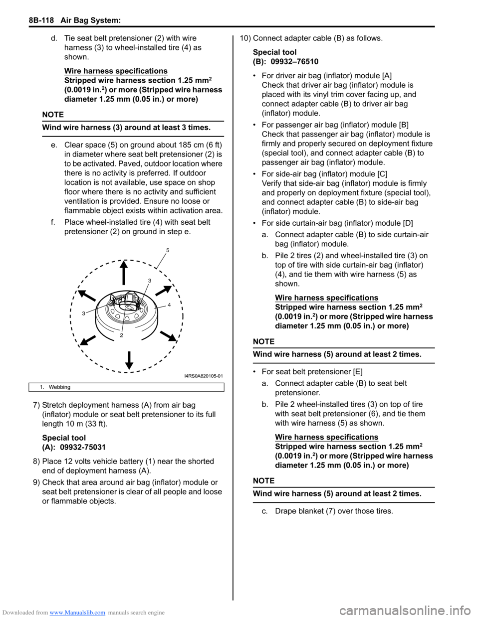
d. Tie seat belt pretensioner (2) with wire harness (3) to wheel-installed tire (4) as
shown.
Wire harness specifications
Stripped wire harness section 1.25 mm2
(0.0019 in.2) or more (Stripped wire harness
diameter 1.25 mm (0.05 in.) or more)
NOTE
Wind wire harness (3) around at least 3 times.
e. Clear space (5) on ground about 185 cm (6 ft) in diameter where seat belt pretensioner (2) is
to be activated. Paved, outdoor location where
there is no activity is preferred. If outdoor
location is not available, use space on shop
floor where there is no activity and sufficient
ventilation is provided. Ensure no loose or
flammable object exists within activation area.
f. Place wheel-installed tire (4) with seat belt pretensioner (2) on ground in step e.
7) Stretch deployment harness (A) from air bag (inflator) module or seat belt pretensioner to its full
length 10 m (33 ft).
Special tool
(A): 09932-75031
8) Place 12 volts vehicle battery (1) near the shorted end of deployment harness (A).
9) Check that area around air bag (inflator) module or seat belt pretensioner is clear of all people and loose
or flammable objects. 10) Connect adapter cable (B) as follows.
Special tool
(B): 09932–76510
• For driver air bag (inflator) module [A]Check that driver air bag (inflator) module is
placed with its vinyl trim cover facing up, and
connect adapter cable (B) to driver air bag
(inflator) module.
• For passenger air bag (inflator) module [B] Check that passenger air bag (inflator) module is
firmly and properly secured on deployment fixture
(special tool), and connect adapter cable (B) to
passenger air bag (inflator) module.
• For side-air bag (inflator) module [C] Verify that side-air bag (inflator) module is firmly
and properly on deployment fixture (special tool),
and connect adapter cable (B) to side-air bag
(inflator) module.
• For side curtain-air bag (inflator) module [D] a. Connect adapter cable (B) to side curtain-air bag (inflator) module.
b. Pile 2 tires (2) and wheel-installed tire (3) on top of tire with side curtain-air bag (inflator)
(4), and tie them with wire harness (5) as
shown.
Wire harness specifications
Stripped wire harness section 1.25 mm2
(0.0019 in.2) or more (Stripped wire harness
diameter 1.25 mm (0.05 in.) or more)
NOTE
Wind wire harness (5) around at least 2 times.
• For seat belt pretensioner [E]
a. Connect adapter cable (B) to seat belt pretensioner.
b. Pile 2 wheel-installed tires (3) on top of tire with seat belt pretensioner (6), and tie them
with wire harness (5) as shown.
Wire harness specifications
Stripped wire harness section 1.25 mm2
(0.0019 in.2) or more (Stripped wire harness
diameter 1.25 mm (0.05 in.) or more)
NOTE
Wind wire harness (5) around at least 2 times.
c. Drape blanket (7) over those tires.
1. Webbing
4
3
3 2 5
I4RS0A820105-01
Page 1170 of 1496

Downloaded from www.Manualslib.com manuals search engine 9-iv Table of Contents
Rear End Door Opener System Symptom Diagnosis .......................................................... 9F-5
Rear End Door Opener System Operation Inspection .......................................................... 9F-5
Repair Instructions ........... ................................... 9F-6
Front Door Lock Assembly Components ............ 9F-6
Front Door Lock Assembly Removal and Installation ......................................................... 9F-6
Front Door Lock Assembly Inspection ................ 9F-8
Power Door Lock Switch In spection.................... 9F-8
Door Key Cylinder Switch Inspection .................. 9F-8
Power Door Lock Actuator Inspection ................. 9F-9
Rear Door Lock Assembly Components ........... 9F-10
Rear Door Lock Assembly Removal and Installation ....................................................... 9F-10
Rear Door Lock Assembly Inspection ............... 9F-10
Rear End Door Lock Assembly Components.... 9F-11
Rear End Door Lock Assembly Removal and Installation ....................................................... 9F-11
Rear End Door Lock Assembly Inspection........ 9F-12
Rear End Door Opener Switch Inspection ........ 9F-12
Replacement of Transmitte r Battery ................. 9F-13
Programming Transmitter Code for Keyless Entry System (Vehicle without Keyless Start
System) ........................................................... 9F-13
Keyless Entry Answer Back Function
Change-over Procedure (If Equipped) ............ 9F-14
Keyless Entry Receiver Removal and
Installation ....................................................... 9F-14
Keyless Entry Receiver and Its Circuit Inspection ........................................................ 9F-15
Specifications .... ................................................. 9F-16
Tightening Torque Specifications ...................... 9F-16
Special Tools and Equipmen t ........................... 9F-16
Recommended Service Material ....................... 9F-16
Seats ............. ............................................ 9G-1
Repair Instructions ............................................. 9G-1
Front Seat Components ..................................... 9G-1
Front Seat Removal and In stallation .................. 9G-2
Rear Seat Components...................................... 9G-3
Rear Seat Removal and Installation................... 9G-4
Specifications .... .................................................. 9G-4
Tightening Torque Specifications ....................... 9G-4
Special Tools and Equipmen t ............................ 9G-4
Recommended Service Material ........................ 9G-4
Interior Trim ................. ............................ 9H-1
Repair Instructions ............ ..................................9H-1
Floor Carpet Removal and Installation ................9H-1
Head Lining Removal and Installation.................9H-1
Console Box Components ..................................9H-2
Specifications ..................... ..................................9H-3
Tightening Torque Specifications ........................9H-3
Hood / Fenders / Doors ...... ...................... 9J-1
Repair Instructions ............ .................................. 9J-1
Hood Removal and Installation ........................... 9J-1
Hood Inspection and Adjustment ........................ 9J-1
Front Fender Components .................................. 9J-2
Front Fender Removal and Installation ............... 9J-2
Front Door Assembly Comp onents ..................... 9J-3
Front Door Assembly Removal and Installation ......................................................... 9J-3
Rear Door Assembly Components...................... 9J-5
Rear Door Assembly Removal and Installation ......................................................... 9J-5
Rear End Door Assembly Components .............. 9J-6
Rear End Door Assembly Removal and Installation ......................................................... 9J-6
Specifications ..................... .................................. 9J-8
Tightening Torque Specifications ........................ 9J-8
Special Tools and Equipmen t ............................. 9J-8
Recommended Service Material ......................... 9J-8
Body Structure............... .......................... 9K-1
Repair Instructions ............ ..................................9K-1
Front Bumper and Rear Bumper Components .... 9K-1
Cowl Top Components........................................ 9K-2
Specifications ..................... ..................................9K-3
Body Dimensions ................................................ 9K-3
Panel Clearance................................................ 9K-10
Paint / Coatings ............. ...........................9L-1
General Description ............................................. 9L-1
Anti-Corrosion Treatment Construction............... 9L-1
Plastic Parts Finishing ......................................... 9L-2
Component Location ............ ............................... 9L-3
Sealant Application Areas ................................... 9L-3
Under Coating Application Areas ........................ 9L-8
Anti-Corrosion Compound Application Area ..... 9L-10
Exterior Trim ...... ...................................... 9M-1
Repair Instructions ......... .................................... 9M-1
Roof Molding Components................................. 9M-1
Splash Guard (If Equipped) Components .......... 9M-2
Page 1314 of 1496
Downloaded from www.Manualslib.com manuals search engine 9C-19 Instrumentation / Driver Info. / Horn:
Installation
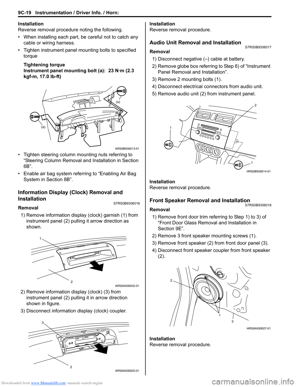
Reverse removal procedure noting the following.
• When installing each part, be careful not to catch any
cable or wiring harness.
• Tighten instrument panel mounting bolts to specified
torque
Tightening torque
Instrument panel mounting bolt (a): 23 N·m (2.3
kgf-m, 17.0 lb-ft)
• Tighten steering column mounting nuts referring to “Steering Column Removal an d Installation in Section
6B”.
• Enable air bag system referring to “Enabling Air Bag System in Section 8B”.
Information Display (Clock) Removal and
Installation
S7RS0B9306016
Removal
1) Remove information display (clock) garnish (1) from instrument panel (2) pulling it arrow direction as
shown.
2) Remove information di splay (clock) (3) from
instrument panel (2) pulli ng it in arrow direction
shown in figure.
3) Disconnect information display (clock) coupler. Installation
Reverse removal procedure.
Audio Unit Removal and InstallationS7RS0B9306017
Removal
1) Disconnect negative (–) cable at battery.
2) Remove globe box referring to Step 6) of “Instrument Panel Removal and Installation”.
3) Remove 2 mounting bolts (1).
4) Disconnect electrical connectors from audio unit.
5) Remove audio unit (2) from instrument panel.
Installation
Reverse removal procedure.
Front Speaker Removal and InstallationS7RS0B9306018
Removal 1) Remove front door trim refe rring to Step 1) to 3) of
“Front Door Glass Remo val and Installation in
Section 9E”.
2) Remove 3 front speaker mounting screws (1).
3) Remove front speaker (2) from front door panel (3).
4) Disconnect front speaker coupler from front speaker (2).
Installation
Reverse removal procedure.
(a) (a)
I4RS0B930013-01
1
2I4RS0A930032-01
3
2I4RS0A930025-01
2
1
1
I4RS0B930014-01
1
2
3
I4RS0A930027-01
Page 1315 of 1496
Downloaded from www.Manualslib.com manuals search engine Instrumentation / Driver Info. / Horn: 9C-20
Rear Speaker Removal and InstallationS7RS0B9306019
Removal
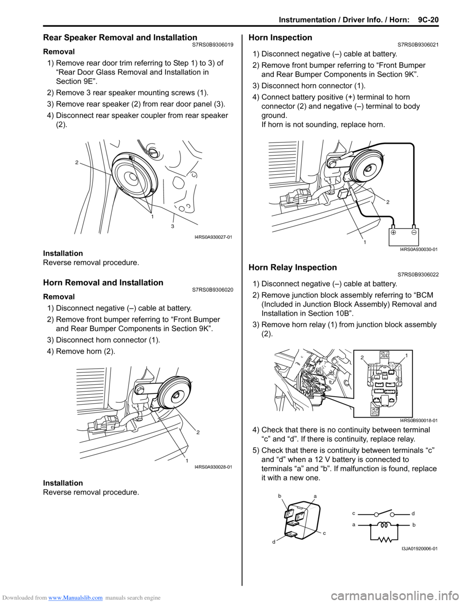
1) Remove rear door trim referring to Step 1) to 3) of “Rear Door Glass Removal and Installation in
Section 9E”.
2) Remove 3 rear speaker mounting screws (1).
3) Remove rear speaker (2) from rear door panel (3).
4) Disconnect rear speaker coupler from rear speaker (2).
Installation
Reverse removal procedure.
Horn Removal and InstallationS7RS0B9306020
Removal 1) Disconnect negative (–) cable at battery.
2) Remove front bumper referring to “Front Bumper and Rear Bumper Components in Section 9K”.
3) Disconnect horn connector (1).
4) Remove horn (2).
Installation
Reverse removal procedure.
Horn InspectionS7RS0B9306021
1) Disconnect negative (–) cable at battery.
2) Remove front bumper referring to “Front Bumper and Rear Bumper Components in Section 9K”.
3) Disconnect horn connector (1).
4) Connect battery positive (+) terminal to horn
connector (2) and negative (–) terminal to body
ground.
If horn is not sounding, replace horn.
Horn Relay InspectionS7RS0B9306022
1) Disconnect negative (–) cable at battery.
2) Remove junction block assembly referring to “BCM (Included in Junction Bl ock Assembly) Removal and
Installation in Section 10B”.
3) Remove horn relay (1) from junction block assembly (2).
4) Check that there is no continuity between terminal “c” and “d”. If there is continuity, replace relay.
5) Check that there is continuity between terminals “c” and “d” when a 12 V battery is connected to
terminals “a” and “b”. If malfunction is found, replace
it with a new one.
1
2
3
I4RS0A930027-01
12I4RS0A930028-01
1 2I4RS0A930030-01
1
2
I4RS0B930018-01
ba
c
d c
a
d
bI3JA01920006-01
Page 1323 of 1496
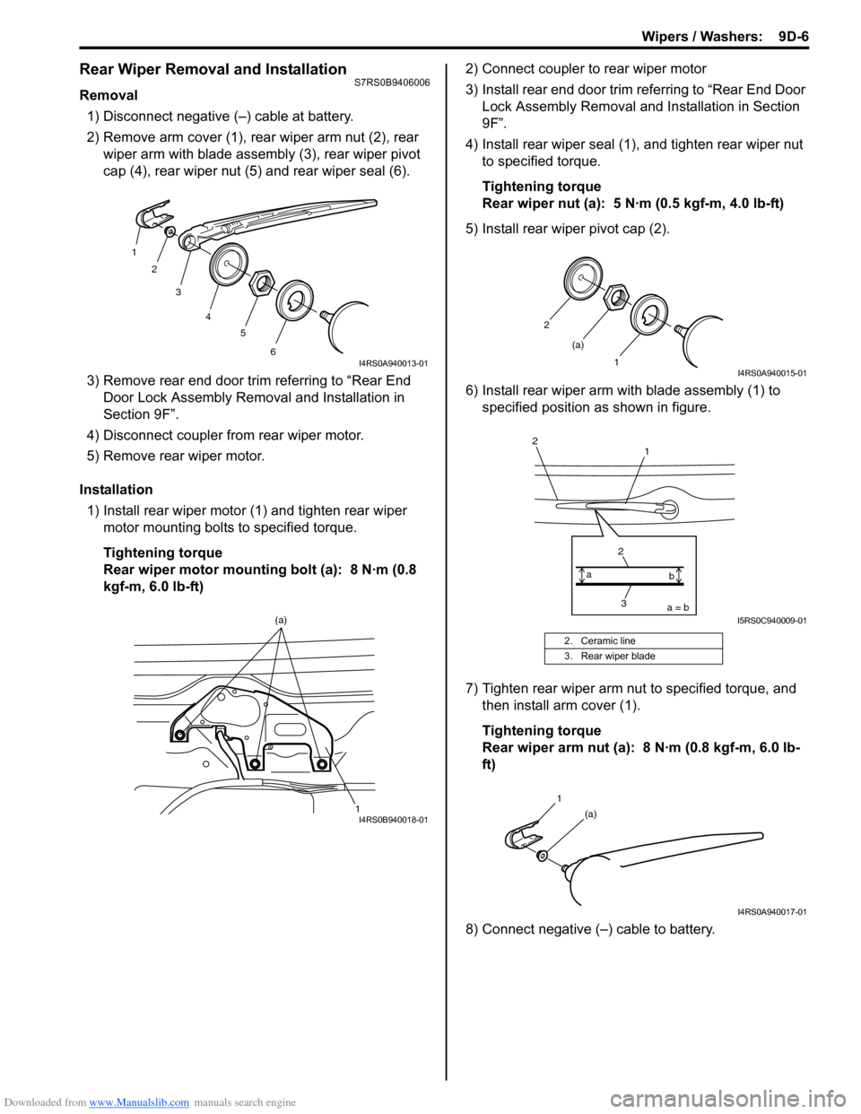
Downloaded from www.Manualslib.com manuals search engine Wipers / Washers: 9D-6
Rear Wiper Removal and InstallationS7RS0B9406006
Removal1) Disconnect negative (–) cable at battery.
2) Remove arm cover (1), rear wiper arm nut (2), rear wiper arm with blade assembly (3), rear wiper pivot
cap (4), rear wiper nut (5) and rear wiper seal (6).
3) Remove rear end door trim referring to “Rear End Door Lock Assembly Remo val and Installation in
Section 9F”.
4) Disconnect coupler from rear wiper motor.
5) Remove rear wiper motor.
Installation 1) Install rear wiper motor (1) and tighten rear wiper motor mounting bolts to specified torque.
Tightening torque
Rear wiper motor mounting bolt (a): 8 N·m (0.8
kgf-m, 6.0 lb-ft) 2) Connect coupler to rear wiper motor
3) Install rear end door trim referring to “Rear End Door
Lock Assembly Removal and Installation in Section
9F”.
4) Install rear wiper seal (1), and tighten rear wiper nut to specified torque.
Tightening torque
Rear wiper nut (a): 5 N·m (0.5 kgf-m, 4.0 lb-ft)
5) Install rear wiper pivot cap (2).
6) Install rear wiper arm with blade assembly (1) to specified position as shown in figure.
7) Tighten rear wiper arm nut to specified torque, and then install arm cover (1).
Tightening torque
Rear wiper arm nut (a): 8 N·m (0.8 kgf-m, 6.0 lb-
ft)
8) Connect negative (–) cable to battery.
1 2
3
4 5
6
I4RS0A940013-01
1
(a)I4RS0B940018-01
2. Ceramic line
3. Rear wiper blade
2
1
(a)
I4RS0A940015-01
1
2
3
2a = b
a
bI5RS0C940009-01
1
(a)
I4RS0A940017-01
Page 1335 of 1496
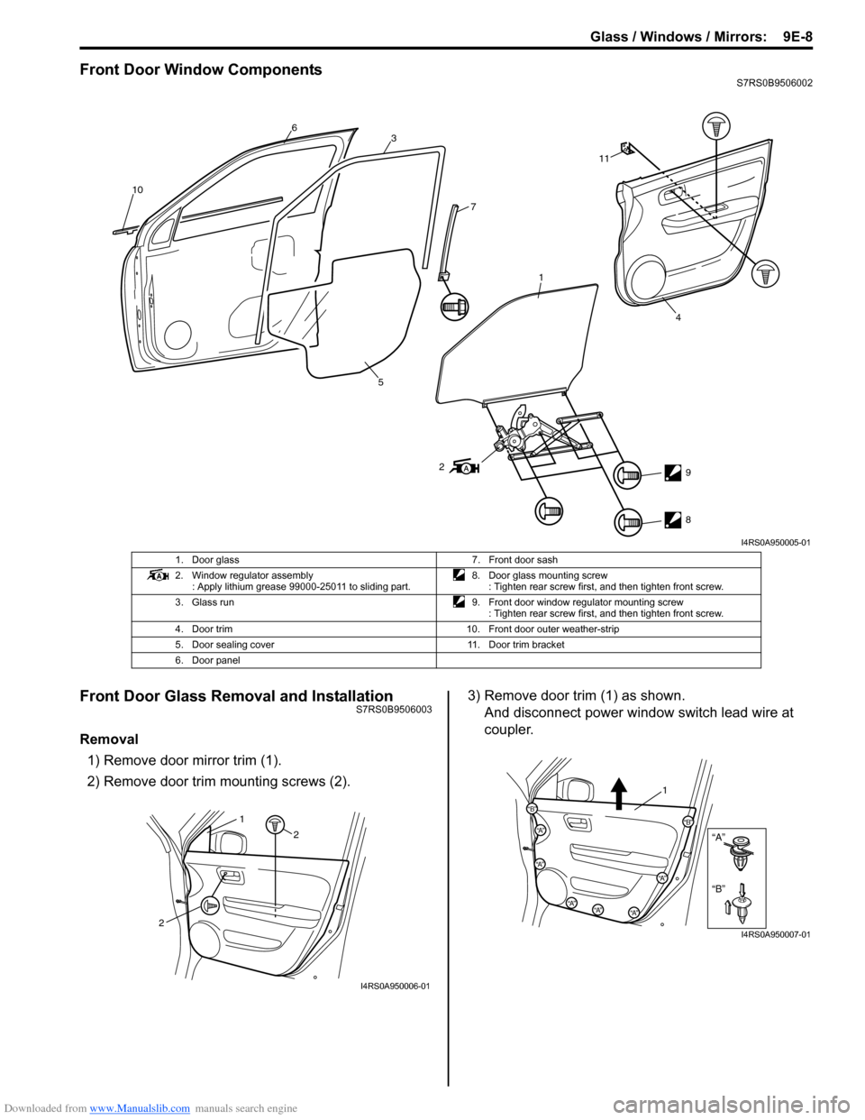
Downloaded from www.Manualslib.com manuals search engine Glass / Windows / Mirrors: 9E-8
Front Door Window ComponentsS7RS0B9506002
Front Door Glass Removal and InstallationS7RS0B9506003
Removal1) Remove door mirror trim (1).
2) Remove door trim mounting screws (2). 3) Remove door trim (1) as shown.
And disconnect power window switch lead wire at
coupler.
10 6
3
1
7
11
5
2 9
8
4
I4RS0A950005-01
1. Door glass 7. Front door sash
2. Window regulator assembly : Apply lithium grease 99000-25011 to sliding part. 8. Door glass mounting screw
: Tighten rear screw first, and then tighten front screw.
3. Glass run 9. Front door window regulator mounting screw
: Tighten rear screw first, and then tighten front screw.
4. Door trim 10. Front door outer weather-strip
5. Door sealing cover 11. Door trim bracket
6. Door panel
2 2
1
I4RS0A950006-01
“B”
“A”
“B”
“A”
“B”“A”
“A”
“A”“A”“A”
1
I4RS0A950007-01