2007 SUZUKI SWIFT crank position
[x] Cancel search: crank positionPage 229 of 1496
Downloaded from www.Manualslib.com manuals search engine Engine General Information and Diagnosis: 1A-179
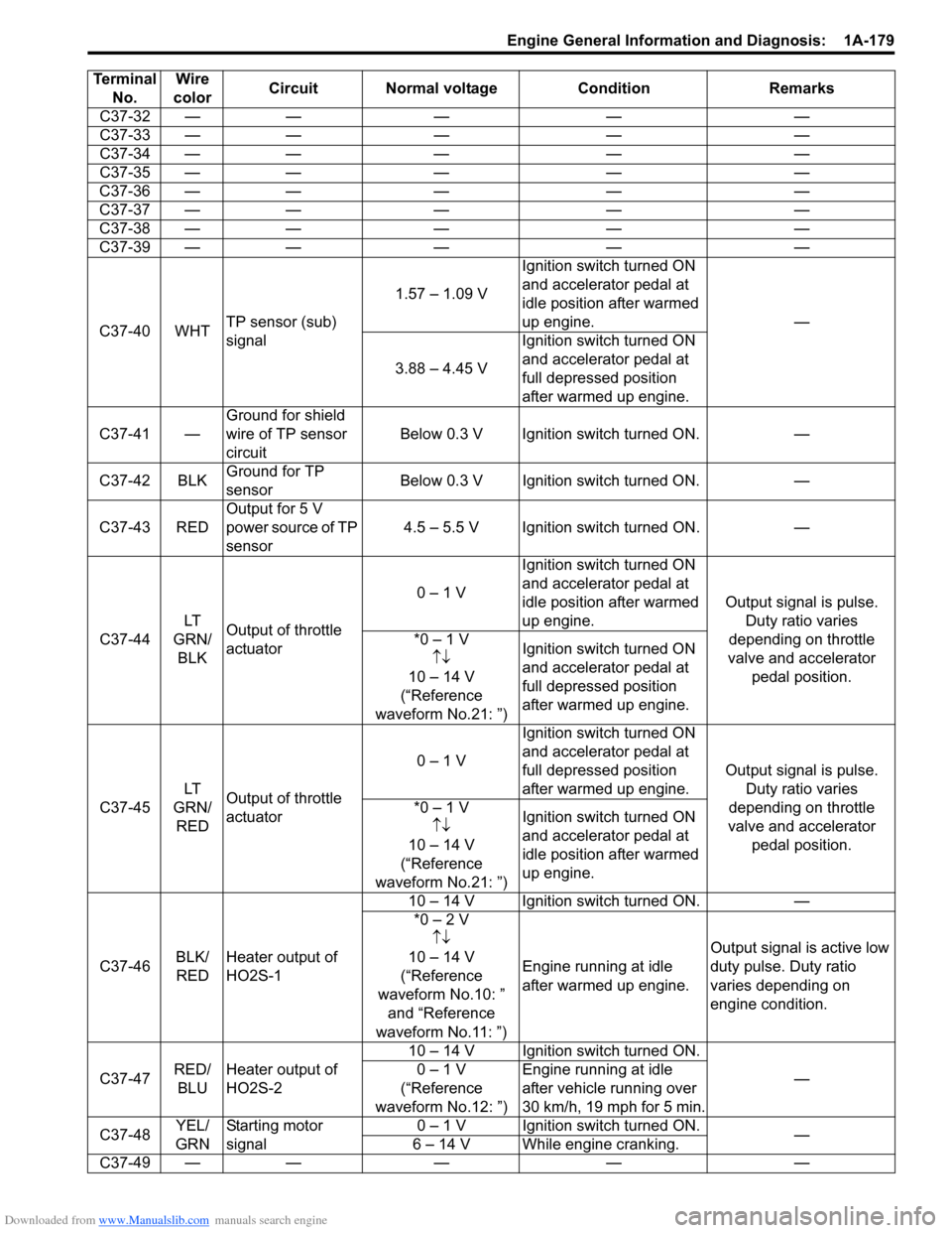
C37-32 ——— — —
C37-33 — —— — —
C37-34 — —— — —
C37-35 — —— — —
C37-36 — —— — —
C37-37 — —— — —
C37-38 — —— — —
C37-39 — —— — —
C37-40 WHT TP sensor (sub)
signal 1.57 – 1.09 V
Ignition switch turned ON
and accelerator pedal at
idle position after warmed
up engine.
—
3.88 – 4.45 V Ignition switch turned ON
and accelerator pedal at
full depressed position
after warmed up engine.
C37-41 — Ground for shield
wire of TP sensor
circuit Below 0.3 V Ignition switch turned ON.
—
C37-42 BLK Ground for TP
sensor Below 0.3 V Ignition switch turned ON.
—
C37-43 RED Output for 5 V
power source of TP
sensor 4.5 – 5.5 V Ignition switch turned ON.
—
C37-44 LT
GRN/ BLK Output of throttle
actuator 0 – 1 V
Ignition switch turned ON
and accelerator pedal at
idle position after warmed
up engine.
Output signal is pulse.
Duty ratio varies
depending on throttle
valve and accelerator pedal position.
*0 – 1 V
↑↓
10 – 14 V
(“Reference
waveform No.21: ”) Ignition switch turned ON
and accelerator pedal at
full depressed position
after warmed up engine.
C37-45 LT
GRN/ RED Output of throttle
actuator 0 – 1 V
Ignition switch turned ON
and accelerator pedal at
full depressed position
after warmed up engine.
Output signal is pulse.
Duty ratio varies
depending on throttle
valve and accelerator pedal position.
*0 – 1 V
↑↓
10 – 14 V
(“Reference
waveform No.21: ”) Ignition switch turned ON
and accelerator pedal at
idle position after warmed
up engine.
C37-46 BLK/
RED Heater output of
HO2S-1 10 – 14 V Ignition switch turned ON.
—
*0 – 2 V ↑↓
10 – 14 V
(“Reference
waveform No.10: ” and “Reference
waveform No.11: ”) Engine running at idle
after warmed up engine.
Output signal is active low
duty pulse. Duty ratio
varies depending on
engine condition.
C37-47 RED/
BLU Heater output of
HO2S-2 10 – 14 V Ignition switch turned ON.
—
0 – 1 V
(“Reference
waveform No.12: ”) Engine running at idle
after vehicle running over
30 km/h, 19 mph for 5 min.
C37-48 YEL/
GRN Starting motor
signal 0 – 1 V Ignition switch turned ON.
—
6 – 14 V While engine cranking.
C37-
49 — —— — —
Terminal
No. Wire
color Circuit Normal voltage
ConditionRemarks
Page 231 of 1496
Downloaded from www.Manualslib.com manuals search engine Engine General Information and Diagnosis: 1A-181
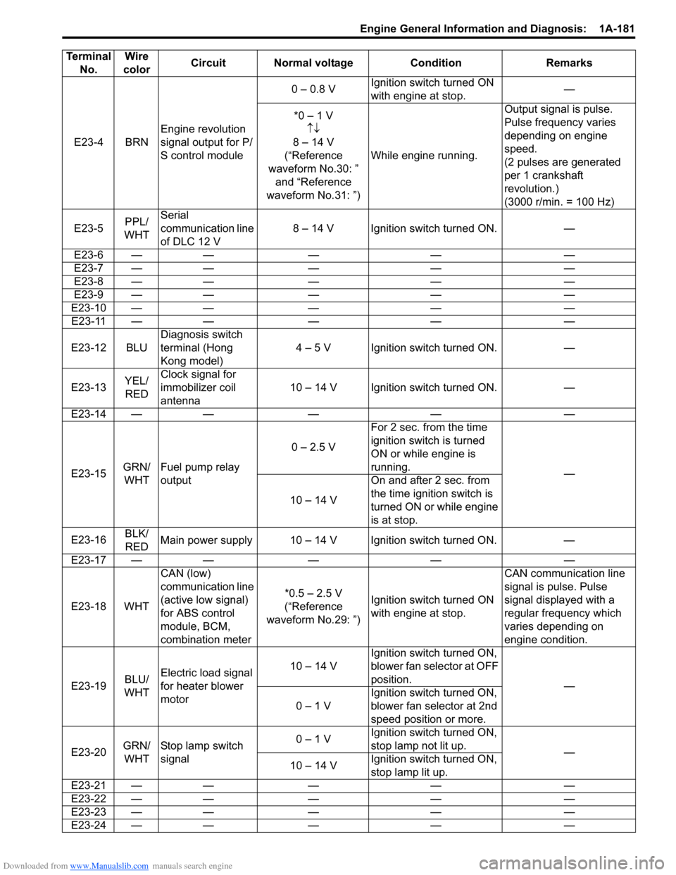
E23-4 BRNEngine revolution
signal output for P/
S control module 0 – 0.8 V
Ignition switch turned ON
with engine at stop. —
*0 – 1 V ↑↓
8 – 14 V
(“Reference
waveform No.30: ” and “Reference
waveform No.31: ”) While engine running. Output signal is pulse.
Pulse frequency varies
depending on engine
speed.
(2 pulses are generated
per 1 crankshaft
revolution.)
(3000 r/min. = 100 Hz)
E23-5 PPL/
WHT Serial
communication line
of DLC 12 V
8 – 14 V Ignition switch turned ON. —
E23-6 — — — — —
E23-7 — — — — —
E23-8 — — — — —
E23-9 — — — — —
E23-10 — — — — — E23-11 — — — — —
E23-12 BLU Diagnosis switch
terminal (Hong
Kong model) 4 – 5 V Ignition switch turned ON. —
E23-13 YEL/
RED Clock signal for
immobilizer coil
antenna
10 – 14 V Ignition switch turned ON. —
E23-14 — — — — —
E23-15 GRN/
WHT Fuel pump relay
output 0 – 2.5 V
For 2 sec. from the time
ignition switch is turned
ON or while engine is
running.
—
10 – 14 V On and after 2 sec. from
the time ignition switch is
turned ON or while engine
is at stop.
E23-16 BLK/
RED Main power supply 10 – 14 V Ignition switch turned ON. —
E23-17 — — — — —
E23-18 WHT CAN (low)
communication line
(active low signal)
for ABS control
module, BCM,
combination meter *0.5 – 2.5 V
(“Reference
waveform No.29: ”) Ignition switch turned ON
with engine at stop. CAN communication line
signal is pulse. Pulse
signal displayed with a
regular frequency which
varies depending on
engine condition.
E23-19 BLU/
WHT Electric load signal
for heater blower
motor 10 – 14 V
Ignition switch turned ON,
blower fan selector at OFF
position.
—
0 – 1 V Ignition switch turned ON,
blower fan selector at 2nd
speed position or more.
E23-20 GRN/
WHT Stop lamp switch
signal 0 – 1 V
Ignition switch turned ON,
stop lamp not lit up.
—
10 – 14 V Ignition switch turned ON,
stop lamp lit up.
E23-21 — — — — —
E23-22 — — — — —
E23-23 — — — — —
E23-24 — — — — —
Terminal
No. Wire
color Circuit Normal voltage Condition Remarks
Page 232 of 1496
Downloaded from www.Manualslib.com manuals search engine 1A-182 Engine General Information and Diagnosis:
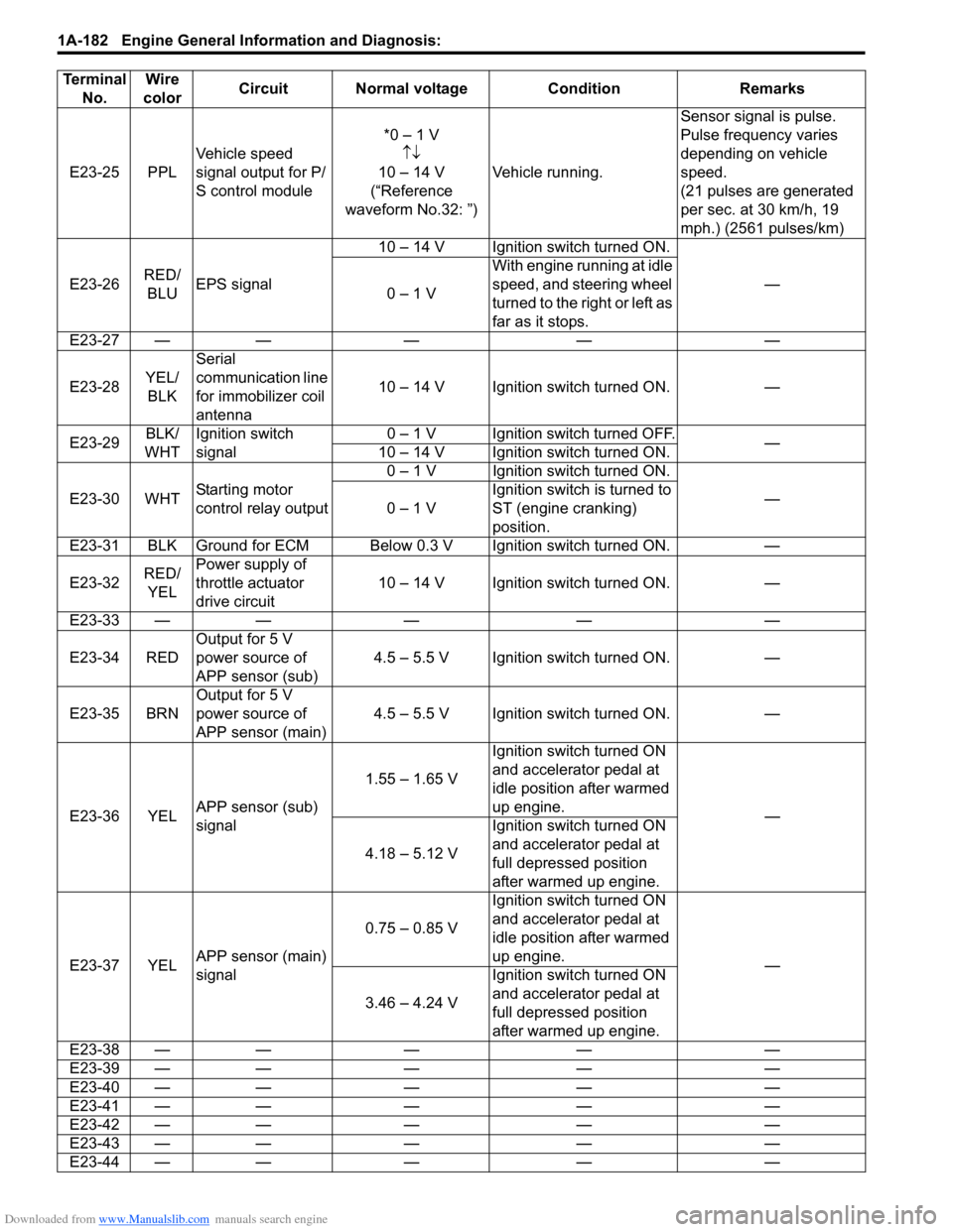
E23-25 PPLVehicle speed
signal output for P/
S control module *0 – 1 V
↑↓
10 – 14 V
(“Reference
waveform No.32: ”) Vehicle running. Sensor signal is pulse.
Pulse frequency varies
depending on vehicle
speed.
(21 pulses are generated
per sec. at 30 km/h, 19
mph.) (2561 pulses/km)
E23-26 RED/
BLU EPS signal 10 – 14 V Ignition switch turned ON.
—
0 – 1 V With engine running at idle
speed, and steering wheel
turned to the right or left as
far as it stops.
E23-27 — — — — —
E23-28 YEL/
BLK Serial
communication line
for immobilizer coil
antenna
10 – 14 V Ignition switch turned ON. —
E23-29 BLK/
WHT Ignition switch
signal 0 – 1 V Ignition switch turned OFF.
—
10 – 14 V Ignition switch turned ON.
E23-30 WHT Starting motor
control relay output 0 – 1 V Ignition switch turned ON.
—
0 – 1 V Ignition switch is turned to
ST (engine cranking)
position.
E23-31 BLK Ground for ECM Below 0.3 V Ignition switch turned ON. —
E23-32 RED/
YEL Power supply of
throttle actuator
drive circuit
10 – 14 V Ignition switch turned ON. —
E23-33 — — — — —
E23-34 RED Output for 5 V
power source of
APP sensor (sub) 4.5 – 5.5 V Ignition switch turned ON. —
E23-35 BRN Output for 5 V
power source of
APP sensor (main) 4.5 – 5.5 V Ignition switch turned ON. —
E23-36 YEL APP sensor (sub)
signal 1.55 – 1.65 V
Ignition switch turned ON
and accelerator pedal at
idle position after warmed
up engine.
—
4.18 – 5.12 V Ignition switch turned ON
and accelerator pedal at
full depressed position
after warmed up engine.
E23-37 YEL APP sensor (main)
signal 0.75 – 0.85 V
Ignition switch turned ON
and accelerator pedal at
idle position after warmed
up engine.
—
3.46 – 4.24 V Ignition switch turned ON
and accelerator pedal at
full depressed position
after warmed up engine.
E23-38 — — — — —
E23-39 — — — — —
E23-40 — — — — —
E23-41 — — — — —
E23-42 — — — — —
E23-43 — — — — —
E23-44 — — — — —
Terminal
No. Wire
color Circuit Normal voltage Condition Remarks
Page 236 of 1496
Downloaded from www.Manualslib.com manuals search engine 1A-186 Engine General Information and Diagnosis:
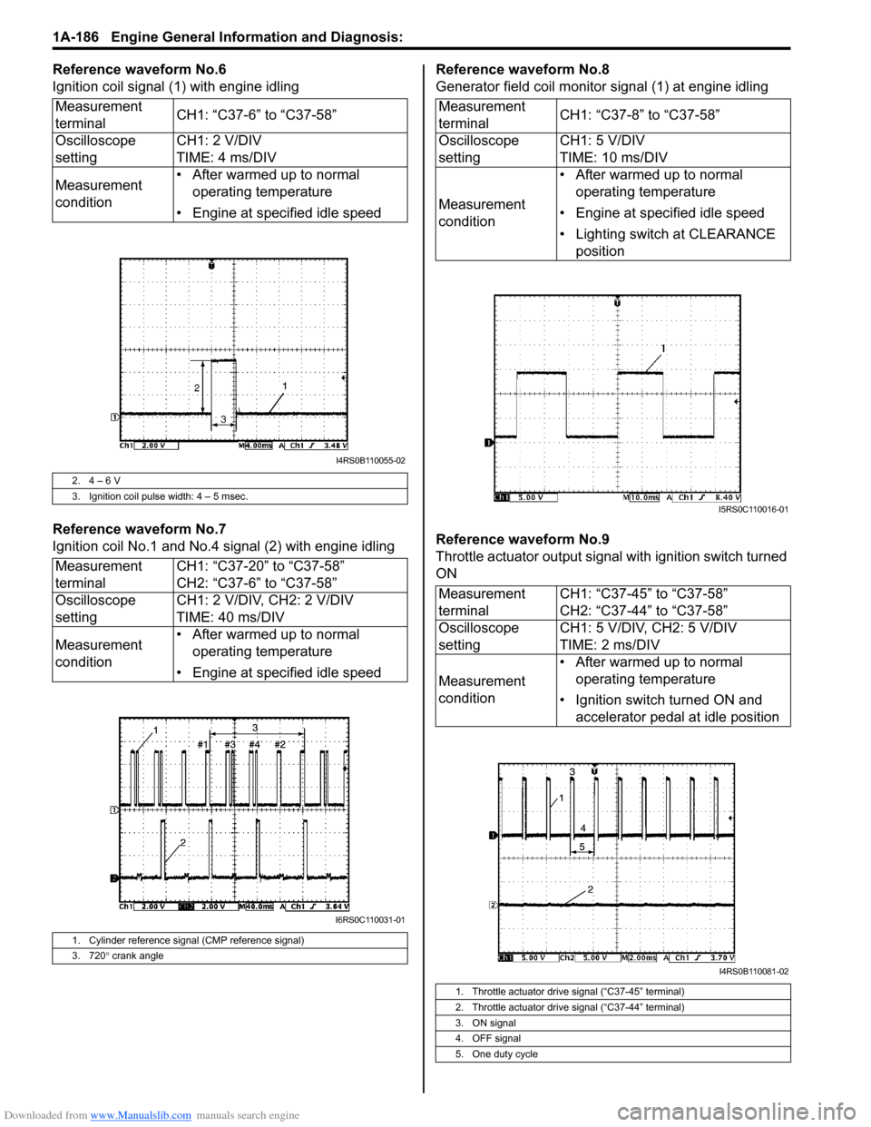
Reference waveform No.6
Ignition coil signal (1) with engine idling
Reference waveform No.7
Ignition coil No.1 and No.4 signal (2) with engine idlingReference waveform No.8
Generator field coil monitor signal (1) at engine idling
Reference waveform No.9
Throttle actuator output signal with ignition switch turned
ON
Measurement
terminal
CH1: “C37-6” to “C37-58”
Oscilloscope
setting CH1: 2 V/DIV
TIME: 4 ms/DIV
Measurement
condition • After warmed up to normal
operating temperature
• Engine at specified idle speed
2. 4 – 6 V
3. Ignition coil pulse width: 4 – 5 msec.
Measurement
terminal CH1: “C37-20” to “C37-58”
CH2: “C37-6” to “C37-58”
Oscilloscope
setting CH1: 2 V/DIV, CH2: 2 V/DIV
TIME: 40 ms/DIV
Measurement
condition • After warmed up to normal
operating temperature
• Engine at specified idle speed
1. Cylinder reference signal (CMP reference signal)
3. 720 ° crank angle
I4RS0B110055-02
I6RS0C110031-01
Measurement
terminal CH1: “C37-8” to “C37-58”
Oscilloscope
setting CH1: 5 V/DIV
TIME: 10 ms/DIV
Measurement
condition • After warmed up to normal
operating temperature
• Engine at specified idle speed
• Lighting switch at CLEARANCE position
Measurement
terminal CH1: “C37-45” to “C37-58”
CH2: “C37-44” to “C37-58”
Oscilloscope
setting CH1: 5 V/DIV, CH2: 5 V/DIV
TIME: 2 ms/DIV
Measurement
condition • After warmed up to normal
operating temperature
• Ignition switch turned ON and accelerator pedal at idle position
1. Throttle actuator drive signal (“C37-45” terminal)
2. Throttle actuator drive signal (“C37-44” terminal)
3. ON signal
4. OFF signal
5. One duty cycle
I5RS0C110016-01
I4RS0B110081-02
Page 240 of 1496
Downloaded from www.Manualslib.com manuals search engine 1A-190 Engine General Information and Diagnosis:
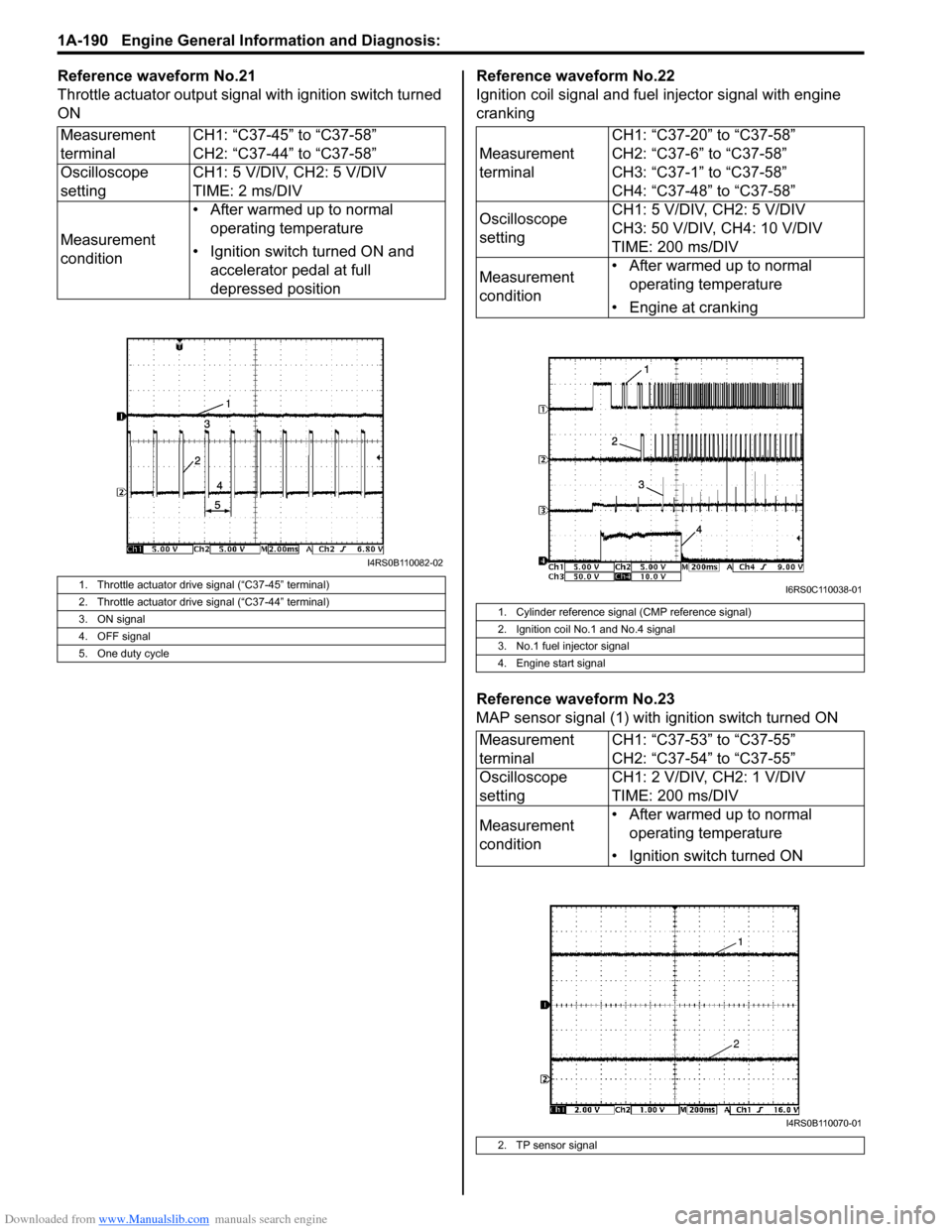
Reference waveform No.21
Throttle actuator output signal with ignition switch turned
ONReference waveform No.22
Ignition coil signal and fuel injector signal with engine
cranking
Reference waveform No.23
MAP sensor signal (1) with ignition switch turned ON
Measurement
terminal
CH1: “C37-45” to “C37-58”
CH2: “C37-44” to “C37-58”
Oscilloscope
setting CH1: 5 V/DIV, CH2: 5 V/DIV
TIME: 2 ms/DIV
Measurement
condition • After warmed up to normal
operating temperature
• Ignition switch turned ON and accelerator pedal at full
depressed position
1. Throttle actuator drive signal (“C37-45” terminal)
2. Throttle actuator drive signal (“C37-44” terminal)
3. ON signal
4. OFF signal
5. One duty cycle
I4RS0B110082-02
Measurement
terminal CH1: “C37-20” to “C37-58”
CH2: “C37-6” to “C37-58”
CH3: “C37-1” to “C37-58”
CH4: “C37-48” to “C37-58”
Oscilloscope
setting CH1: 5 V/DIV, CH2: 5 V/DIV
CH3: 50 V/DIV, CH4: 10 V/DIV
TIME: 200 ms/DIV
Measurement
condition • After warmed up to normal
operating temperature
• Engine at cranking
1. Cylinder reference signal (CMP reference signal)
2. Ignition coil No.1 and No.4 signal
3. No.1 fuel injector signal
4. Engine start signal
Measurement
terminal CH1: “C37-53” to “C37-55”
CH2: “C37-54” to “C37-55”
Oscilloscope
setting CH1: 2 V/DIV, CH2: 1 V/DIV
TIME: 200 ms/DIV
Measurement
condition • After warmed up to normal
operating temperature
• Ignition switch turned ON
2. TP sensor signal
I6RS0C110038-01
I4RS0B110070-01
Page 287 of 1496
Downloaded from www.Manualslib.com manuals search engine Engine Mechanical: 1D-2
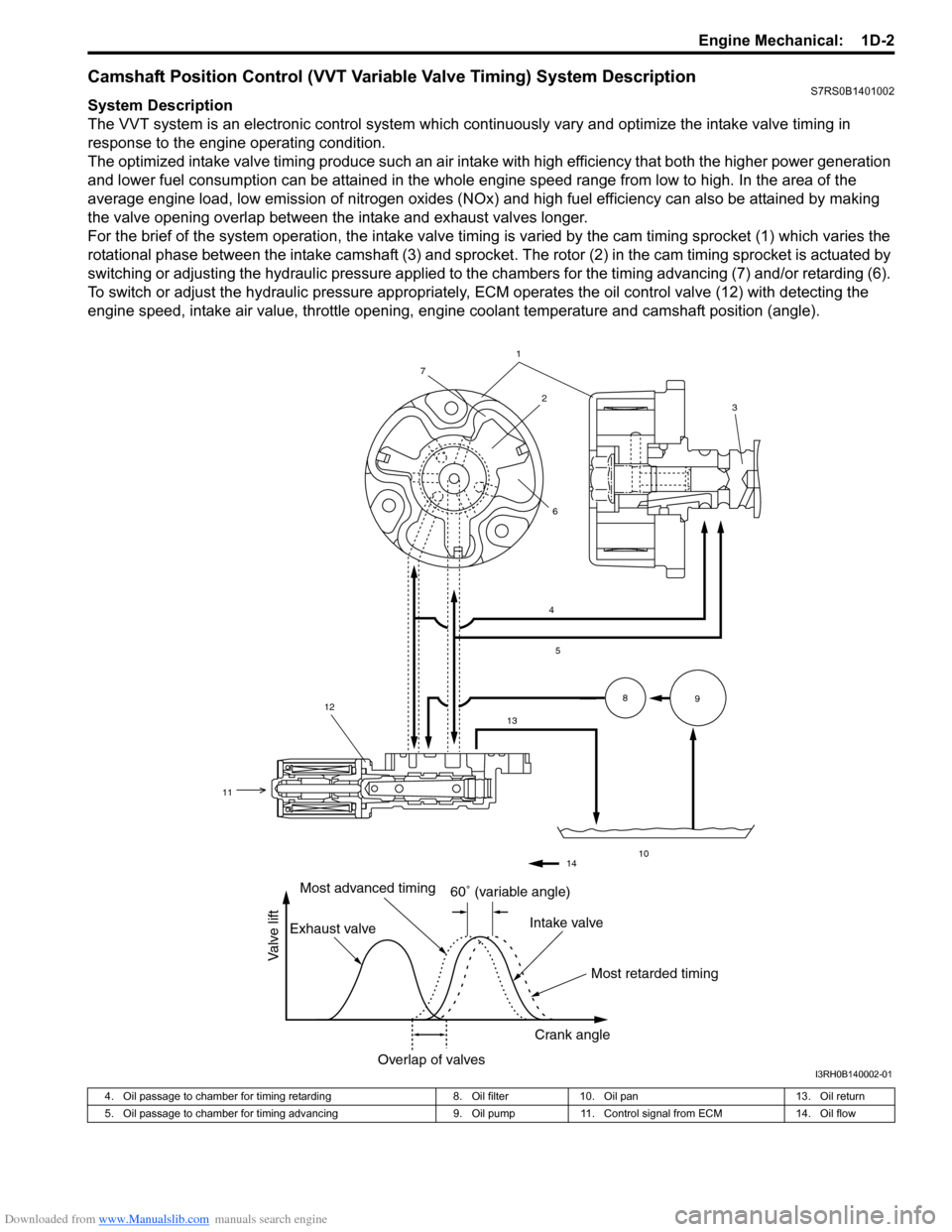
Camshaft Position Control (VVT Variable Valve Timing) System DescriptionS7RS0B1401002
System Description
The VVT system is an electronic control system which continuously vary and optimize the intake valve timing in
response to the engine operating condition.
The optimized intake valve timing produce such an air intake with high efficiency that both the higher power generation
and lower fuel consumption can be attained in the whole engine speed range from low to high. In the area of the
average engine load, low emission of nitrogen oxides (NOx) and high fuel efficiency can also be attained by making
the valve opening overlap between the intake and exhaust valves longer.
For the brief of the system operation, the intake valve timing is varied by the cam timing sprocket (1) which varies the
rotational phase between the intake camshaft (3) and sprocket . The rotor (2) in the cam timing sprocket is actuated by
switching or adjusting the hydraulic pressure applied to the chambers for the timing advancing (7) and/or retarding (6).
To switch or adjust the hydraulic pressure appropriately, ECM operates the oil control valve (12) with detecting the
engine speed, intake air value, throttle opening, engine coolant temperature and camshaft position (angle).
1
4
5
13
10
89
2
7
6
12
11
3
14
60� (variable angle)
Most retarded timing
Most advanced timing
Exhaust valve Intake valve
Crank angle
Overlap of valves
Valve lift
I3RH0B140002-01
4. Oil passage to chamber for timing retarding 8. Oil filter10. Oil pan 13. Oil return
5. Oil passage to chamber for timing advancing 9. Oil pump11. Control signal from ECM 14. Oil flow
Page 292 of 1496

Downloaded from www.Manualslib.com manuals search engine 1D-7 Engine Mechanical:
Replacement of Shim1) Close the valve whose shim (2) is to be replaced by turning crankshaft, then tu rn tappet (3) till its cut
section (1) faces inside as shown in the figure.
2) Lift down the valve by turning crankshaft to 360° .
3) Hold tappet at that position using special tool as follows.
a) Remove its housing bolts.
b) Check housing No. and select special tool corresponding to housing No., referring to
“Special tool selection table”.
Special tool selection table
c) Hold down the tappet so as not to contact the shim by installing special tool on camshaft
housing with housing bolt (1) tighten housing
bolts by hand.
Special tool
(A): 09916–67020
(A): 09916–67021 4) Turn camshaft by approximately 90
° clockwise and
remove shim (3).
WARNING!
Never put in the hand between camshaft and
tappet.
5) Using a micrometer (2), measure the thickness of the removed shim (1), and determine replacement
shim by calculating the thickness of new shim with
the following formula and table.
Shim thickness specification
Intake side:
A = B + C – 0.20 mm (0.008 in.)
Exhaust side:
A = B + C – 0.30 mm (0.012 in.)
A: Thickness of new shim
B: Thickness of removed shim
C: Measured valve clearance
No. on camshaft
housing Embossed mark on
special tool
I2 IN2
I3, I4, I5 IN345
E2 EX2
E3, E4, E5 EX345
A: I: Intake side or E: Exhaust side
B: Position from timing chain side
C: Pointing to timing chain side
I2RH0B140006-01
I2RH0B140011-01
1. Special tool
2. Magnet
I6RS0B141028-01
I2RH0B140013-01
I2RH0B140014-01
Page 310 of 1496

Downloaded from www.Manualslib.com manuals search engine 1D-25 Engine Mechanical:
Timing Chain and Chain Tensioner Removal
and Installation
S7RS0B1406018
Removal
CAUTION!
After timing chain is removed, never turn
crankshaft and camshafts independently
more than its allowable turning range
described in “Installation”.
If turned, interferen ce may occur between
piston and valves and valves themselves,
and parts related to piston and valves may be
damaged.
1) Remove timing chain cover referring to “Timing Chain Cover Removal and Installation”.
2) By turning crankshaft, align camshafts and crankshaft at specific position as follows.
a) Align both intake and exhaust camshaft timing sprocket marks (1) with notches (2) of cylinder
head respectively.
b) Align crankshaft sprocket key (3) with notch of cylinder block (4).
Position crankshaft sprocke t key (3) at upside of
crankshaft as shown in figure.
3) Remove timing chain tensioner adjuster assembly (5).
4) Remove timing chain tensioner (6).
5) Remove timing chain No.1 guide (7).
6) Remove timing chain (8) with crankshaft timing sprocket (9). Installation
CAUTION!
After timing chain is removed, never turn
crankshaft and camshafts independently
more than such an extent (“a”, “b”) as shown
in figure.
If turned, interferen
ce may occur between
piston and valves and valves themselves,
and parts related to piston and valves may be
damaged.
1) Check that match marks (1) on intake and exhaust camshaft timing sprockets are in match with notches
(2) on cylinder head as shown in figure.
2) Set key (3) and turn crankshaft to position key on upside of crankshaft.
3
4
1
1
2
5
67
8
9
I3RH0B140032-01
“a”: 90 °4. Camshaft (IN and EX) allowable turning range.
By marks on camshaft timing sprocket within 15 ° from notches
on cylinder head on both right and left.
“b”: 15 °5. Crankshaft allowable turning range.
By key on crankshaft, within 90 ° from top on both right and left.
“a”
“b”
“b”“b”
“b”
“a”
1
12
4
3
5
I4RS0A140021-01