2007 SUZUKI SWIFT Code on key lock
[x] Cancel search: Code on key lockPage 540 of 1496
Downloaded from www.Manualslib.com manuals search engine 4E-1 ABS:
Brakes
ABS
Precautions
Precautions in Diagnosing TroublesS7RS0B4500001
To ensure that the trouble diagnosis is done accurately
and smoothly, observe the following and follow “ABS
Check”.
• Diagnostic information stored in ABS cont rol module
memory can be cleared as well as checked by using
SUZUKI scan tool. Before us ing scan tool, read its
Operator’s (Instruction) Manual carefully to have good
understanding as to what functions are available and
how to use it.
• If the vehicles was operated in any of the following ways, ABS warning light may light momentarily but
this does not indicate anything abnormal in ABS.
– The vehicle was driven with parking brake pulled.
– The vehicle was driven with brake dragging.
– The vehicle was stuck in mud, sand, etc.
– Wheel spin occurred while driving.
– Wheel(s) was rotated while the vehicle was jacked up.
• Be sure to read “Precautions for Electrical Circuit Service in Section 00” befo re inspection and observe
what is written there.
• Be sure to use the trouble diagnosis procedure as described in “ABS Check”. Failure to follow it may
result in incorrect diagnosis. (Some other diagnosis
trouble code may be stored by mistake in the memory
of ABS control module during inspection.)
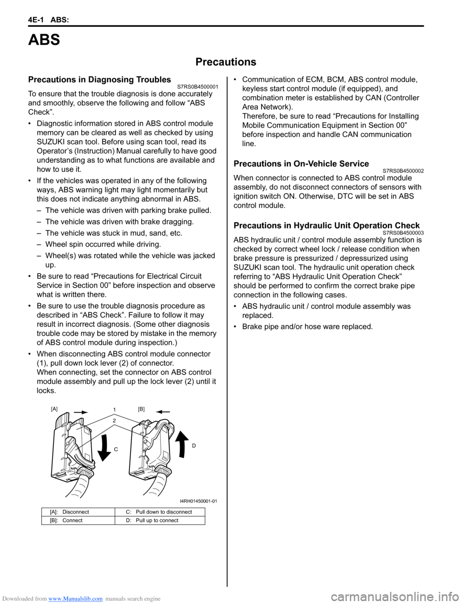
• When disconnecting ABS co ntrol module connector
(1), pull down lock lever (2) of connector.
When connecting, set the connector on ABS control
module assembly and pull up the lock lever (2) until it
locks. • Communication of ECM,
BCM, ABS control module,
keyless start control module (if equipped), and
combination meter is established by CAN (Controller
Area Network).
Therefore, be sure to read “Precautions for Installing
Mobile Communication Equipment in Section 00”
before inspection and handle CAN communication
line.
Precautions in On-Vehicle ServiceS7RS0B4500002
When connector is connected to ABS control module
assembly, do not disconnect connectors of sensors with
ignition switch ON. Otherwise, DTC will be set in ABS
control module.
Precautions in Hydraulic Unit Operation CheckS7RS0B4500003
ABS hydraulic unit / control module assembly function is
checked by correct wheel lock / release condition when
brake pressure is pressurized / depressurized using
SUZUKI scan tool. The hydraulic unit operation check
referring to “ABS Hydraulic Unit Operation Check”
should be performed to confirm the correct brake pipe
connection in the following cases.
• ABS hydraulic unit / cont rol module assembly was
replaced.
• Brake pipe and/or hose ware replaced.
[A]: Disconnect C: Pull down to disconnect
[B]: Connect D: Pull up to connect
21
C D
[A]
[B]
I4RH01450001-01
Page 575 of 1496
Downloaded from www.Manualslib.com manuals search engine Electronic Stability Program: 4F-1
Brakes
Electronic Stability Program
Precautions
Precautions in Diagnosing TroublesS7RS0B4600001
To ensure that the trouble diagnosis is done accurately
and smoothly, observe the following and follow
“Electronic Stability Program System Check”.
• Diagnostic information stored in ESP® control module
memory can be cleared as well as checked by using
SUZUKI scan tool. Before us ing scan tool, read its
Operator’s (Instruction) Manual carefully to have good
understanding as to what functions are available and
how to use it.
• If the vehicles was operated in any of the following ways, ESP ® warning lamp may light momentarily but
this does not indicate anything abnormal in ESP ®.
– The vehicle was driven with parking brake pulled.
– The vehicle was driven with brake dragging.
– The vehicle was stuck in mud, sand, etc.
– Wheel spin occurred while driving.
– Wheel(s) was rotated while the vehicle was jacked up.
• Be sure to use the trouble diagnosis procedure as described in “Electronic Stability Program System
Check”. Failure to follow it may resu lt in incorrect
diagnosis. (Some other diagnosis trouble code may
be stored by mistake in the memory of ESP ® control
module during inspection.)
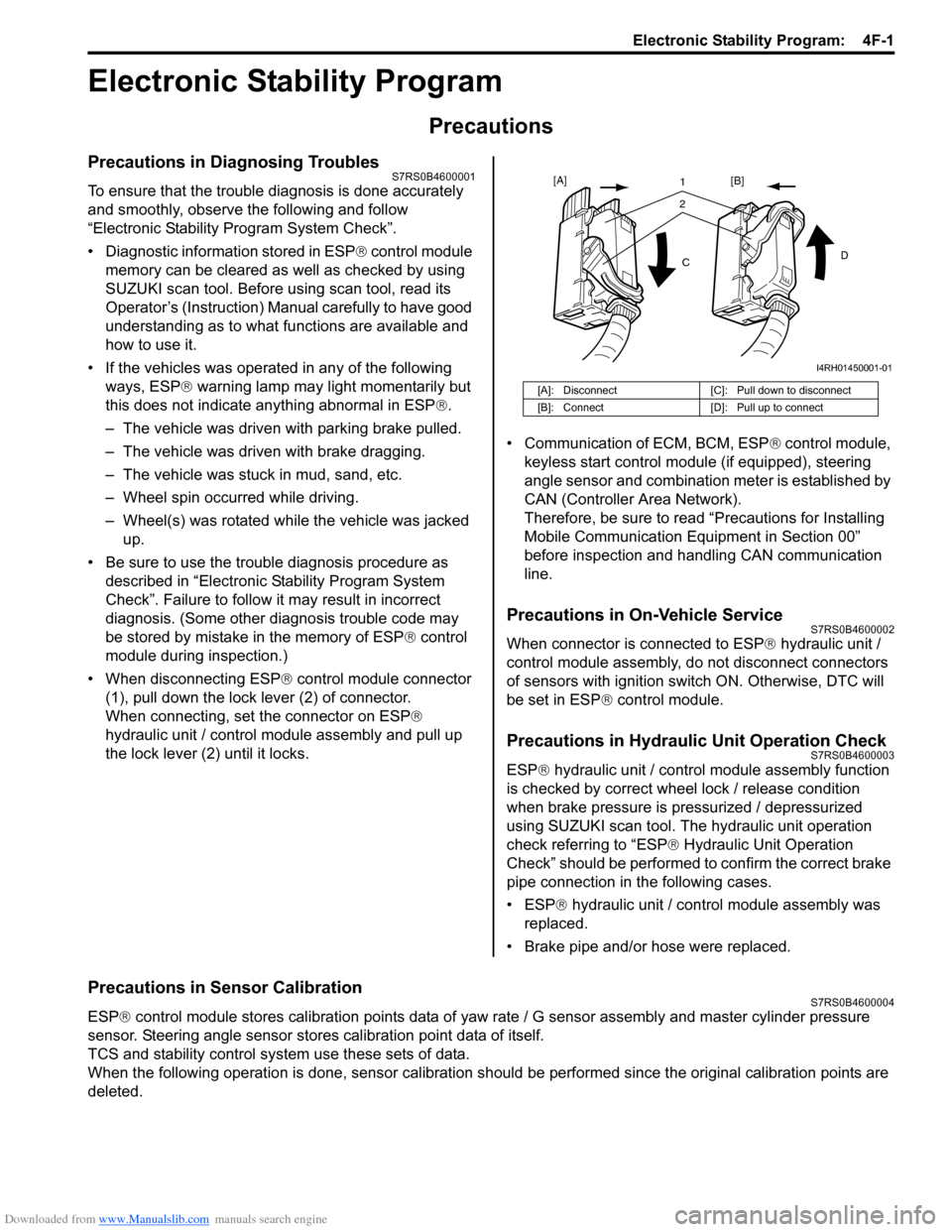
• When disconnecting ESP ® control module connector
(1), pull down the lock lever (2) of connector.
When connecting, set the connector on ESP ®
hydraulic unit / control module assembly and pull up
the lock lever (2) until it locks. • Communication of ECM, BCM, ESP
® control module,
keyless start control module (if equipped), steering
angle sensor and combination meter is established by
CAN (Controller Area Network).
Therefore, be sure to read “Precautions for Installing
Mobile Communication Equipment in Section 00”
before inspection and handling CAN communication
line.
Precautions in On-Vehicle ServiceS7RS0B4600002
When connector is connected to ESP ® hydraulic unit /
control module assembly, do not disconnect connectors
of sensors with ignition switch ON. Otherwise, DTC will
be set in ESP ® control module.
Precautions in Hydraulic Unit Operation CheckS7RS0B4600003
ESP® hydraulic unit / control module assembly function
is checked by correct wheel lock / release condition
when brake pressure is pressurized / depressurized
using SUZUKI scan tool. The hydraulic unit operation
check referring to “ESP ® Hydraulic Unit Operation
Check” should be performed to confirm the correct brake
pipe connection in the following cases.
• ESP® hydraulic unit / contro l module assembly was
replaced.
• Brake pipe and/or hose were replaced.
Precautions in Sensor CalibrationS7RS0B4600004
ESP ® control module stores calibration points data of yaw rate / G sensor assembly and master cylinder pressure
sensor. Steering angle sensor stores calibration point data of itself.
TCS and stability control system use these sets of data.
When the following operation is done, sensor calibration should be performed since the original calibration points are
deleted.
[A]: Disconnect [C]: Pull down to disconnect
[B]: Connect [D]: Pull up to connect
21
C D
[A]
[B]
I4RH01450001-01
Page 880 of 1496
Downloaded from www.Manualslib.com manuals search engine 6B-9 Steering Wheel and Column:
Ignition Switch Cylinder Assembly Removal
and Installation (Non- Keyless Start Model)
S7RS0B6206008
Removal1) Disconnect negative (–) cable at battery.
2) Disable air bag system referring to “Disabling Air Bag System in Section 8B”.
3) Remove steering column upper and lower covers.
4) Remove immobilizer co ntrol module referring to
“Immobilizer Control Modu le (ICM) Removal and
Installation in Section 10C”.
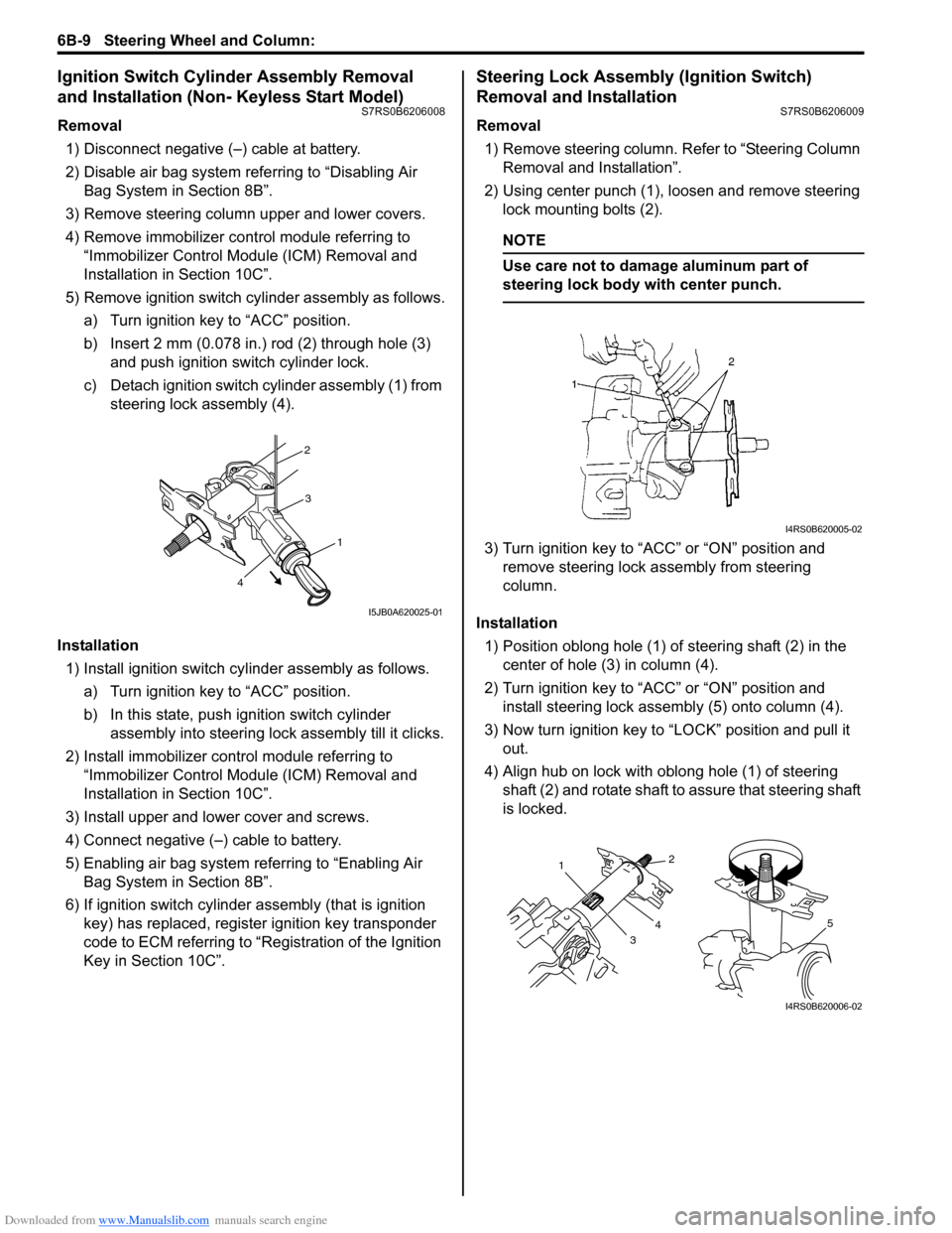
5) Remove ignition switch cy linder assembly as follows.
a) Turn ignition key to “ACC” position.
b) Insert 2 mm (0.078 in.) rod (2) through hole (3) and push ignition switch cylinder lock.
c) Detach ignition switch cylinder assembly (1) from steering lock assembly (4).
Installation 1) Install ignition switch cy linder assembly as follows.
a) Turn ignition key to “ACC” position.
b) In this state, push ignition switch cylinder assembly into steering lock assembly till it clicks.
2) Install immobilizer cont rol module referring to
“Immobilizer Control Modu le (ICM) Removal and
Installation in Section 10C”.
3) Install upper and lower cover and screws.
4) Connect negative (–) cable to battery.
5) Enabling air bag system referring to “Enabling Air Bag System in Section 8B”.
6) If ignition switch cylinder assembly (that is ignition
key) has replaced, register ignition key transponder
code to ECM referring to “R egistration of the Ignition
Key in Section 10C”.
Steering Lock Assembly (Ignition Switch)
Removal and Installation
S7RS0B6206009
Removal
1) Remove steering column. Refer to “Steering Column
Removal and Installation”.
2) Using center punch (1), loosen and remove steering lock mounting bolts (2).
NOTE
Use care not to damage aluminum part of
steering lock body with center punch.
3) Turn ignition key to “ACC” or “ON” position and remove steering lock a ssembly from steering
column.
Installation 1) Position oblong hole (1) of steering shaft (2) in the center of hole (3) in column (4).
2) Turn ignition key to “ACC” or “ON” position and install steering lock assemb ly (5) onto column (4).
3) Now turn ignition key to “LOCK” position and pull it out.
4) Align hub on lock with oblong hole (1) of steering shaft (2) and rotate shaft to assure that steering shaft
is locked.
2
3
1
4
I5JB0A620025-01
I4RS0B620005-02
1
32
4
5
I4RS0B620006-02
Page 881 of 1496

Downloaded from www.Manualslib.com manuals search engine Steering Wheel and Column: 6B-10
5) Tighten new bolts (1) until head of each bolt is broken off.
6) Turn ignition key to “ACC” or “ON” position and check to be sure that st eering shaft (2) rotates
smoothly. Also check for lock operation.
7) Install steering column. Re fer to “Steering Column
Removal and Installation”.
8) If steering lock assembly has replaced, after completing installation, register ignition key
transponder code in ECM referring to “Registration
of the Ignition Key in Section 10C”.
Steering Lower Shaft Removal and InstallationS7RS0B6206010
CAUTION!
Never turn steering wheel while steering
lower shaft is removed.
Should it have been turned and contact coil
have got out of its centered position, it needs
to be centered again. Also, turning steering
wheel more than about two and a half turns
will break contact coil.
Removal
1) Turn steering wheel so that vehicle’s front tires are at straight-ahead position.
2) Turn ignition switch to LOCK position and remove key.
3) Remove steering joint cover.
4) Make alignment marks (4) on lower shaft (1) and shaft joint of steering colu mn (2) and lower shaft (1)
and pinion shaft (3) for a guide during reinstallation.
5) Remove lower shaf t joint bolts (5).
6) Remove steering lower shaft (1). Installation
1) Be sure that front wheels are in straight forward state.
2) Align flat part “A” of steering lower shaft (1) with bolt hole “B” of shaft joint (2) of column as shown. Then
insert lower shaft into shaf t joint of steering column
with matching marks (4).
3) Insert lower shaft (1) into pinion shaft (3) with matching marks (4).
4) Tighten joint bolt (pinion shaft side) (6) to specified
torque first and then joint bolt (steering column side)
(5) to specified torque.
Tightening torque
Steering shaft joint bolt (a ): 25 N·m (2.5 kgf-m,
18.5 lb-ft)
I4RS0B620007-02
I4RS0A620020-01
I6RS0C620002-01
Page 1167 of 1496

Downloaded from www.Manualslib.com manuals search engine Table of Contents 9- i
9
Section 9
CONTENTS
Body, Cab and Accessories
Precautions ................................................. 9-1
Precautions............................................................. 9-1
Precautions on Body, Cab and Accessories ......... 9-1
Precautions for Body Service ................................ 9-1
Fastener Caution for Body Service ....................... 9-1
Wiring Systems............... ......................... 9A-1
Precautions........................................................... 9A-1
Cautions in Body Electrical System Servicing..... 9A-1
General Description ............................................. 9A-1 Abbreviations ...................................................... 9A-1
Wire / Connector Color Sy mbols ......................... 9A-1
Symbols and Marks ............................................ 9A-2
How to Read Connector Layout Diagram ........... 9A-4
How to Read Connector Codes and Terminal Nos.................................................................... 9A-5
How to Read Ground Point ................................. 9A-7
How to Read Power Supply Diagram.................. 9A-8
How to Read System Circuit Diagram................. 9A-8
Connector Layout Diagram . .............................. 9A-10
Connector Layout Diagram ............................... 9A-10
Engine Compartment .......... .............................. 9A-10
Instrument Panel ............................................... 9A-16
Door, Roof......................................................... 9A-20
Floor .................................................................. 9A-23
Rear .................................................................. 9A-29
Ground Point ...................................................... 9A-30 Ground (earth) Point ......................................... 9A-30
Power Supply Diagram ........ .............................. 9A-31
Power Supply Diagram ....... .............................. 9A-31
Fuses and the Protected Parts ......................... 9A-33
Fuses in Main Fuse Box (RHD) ........................ 9A-33
Fuses in Main Fuse Box (LHD) ......................... 9A-33
Individual Circuit Fuse Box No. 1 ...................... 9A-34
Individual Circuit Fuse Box No. 2 (In J/B) ......... 9A-35
Junction Block (J/B) Connector / Fuse Layout .. 9A-37
Junction Block Inner Circuit (Overview) ............ 9A-38
Junction Block Inner Circuit (Detail) .................. 9A-40
System Circuit Diagram... .................................. 9A-45
System Circuit Diagram .. .................................. 9A-45
A-1 Cranking System Circ uit Diagram .............. 9A-46
A-2 Charging System Circu it Diagram .............. 9A-47
A-3 Ignition System Circu it Diagram ................. 9A-48
A-4 Cooling System Circuit Diagram................. 9A-49 A-5 Engine and A/C Control System Circuit
Diagram........................................................... 9A-50
A-6 A/T Control System Circuit Diagram........... 9A-55
A-7 Immobilizer System Circuit Diagram .......... 9A-57
A-8 Body Control System Circuit Diagram ........ 9A-58
B-1 Windshield Wiper and Washer Circuit Diagram........................................................... 9A-62
B-2 Rear Wiper and Washer Circuit Diagram ... 9A-63
B-3 Rear Defogger Circuit Diagram .................. 9A-64
B-4 Power Window Circuit Diagram .................. 9A-65
B-5 Power Door Lock Circu it Diagram .............. 9A-67
B-6 Power Mirror Circuit Diagram ..................... 9A-69
B-7 Horn Circuit Diagram .................................. 9A-70
B-8 Seat Heater Circuit Diagram....................... 9A-71
B-9 Keyless Start System Circuit Diagram........ 9A-72
C-1 Combination Mete r Circuit Diagram
(Meter)............................................................. 9A-73
C-2 Combination Mete r Circuit Diagram
(Indicator) ........................................................ 9A-74
C-3 Combination Mete r Circuit Diagram
(Warning Light)................................................ 9A-75
D-1 Headlight System Circuit Diagram ............. 9A-77
D-2 Position, Tail and Licence Plate Light System Circuit Diagram .................................. 9A-79
D-3 Front Fog Light System Circuit Diagram .... 9A-80
D-4 Illumination Light System Circuit Diagram .. 9A-81
D-5 Interior Light System Circuit Diagram......... 9A-82
D-6 Turn Signal and Hazard Warning Light System Circuit Diagram .................................. 9A-83
D-7 Brake Light System Circuit Diagram .......... 9A-85
D-8 Back-Up Light System Circuit Diagram ...... 9A-86
D-9 Headlight Beam Leveling System Circuit Diagram........................................................... 9A-87
D-10 Rear Fog Light Circuit Diagram ................ 9A-88
E-1 Heater System Circuit Diagram .................. 9A-89
E-2 Auto A/C System Circuit Diagram .............. 9A-91
F-1 Air-Bag System Circuit Diagram ................. 9A-93
F-2 Anti-Lock Brake System Circuit Diagram.... 9A-95
F-3 Electronic Stab ility Program System
Circuit Diagram .................. ............................. 9A-97
F-4 Power Steering System Circuit Diagram .... 9A-99
G-1 Audio System Circuit Diagram ................. 9A-101
G-2 Multi Information Display / Accessory Socket System Circuit Diagram .................... 9A-102
List of Connector .............................................9A-103
Page 1170 of 1496

Downloaded from www.Manualslib.com manuals search engine 9-iv Table of Contents
Rear End Door Opener System Symptom Diagnosis .......................................................... 9F-5
Rear End Door Opener System Operation Inspection .......................................................... 9F-5
Repair Instructions ........... ................................... 9F-6
Front Door Lock Assembly Components ............ 9F-6
Front Door Lock Assembly Removal and Installation ......................................................... 9F-6
Front Door Lock Assembly Inspection ................ 9F-8
Power Door Lock Switch In spection.................... 9F-8
Door Key Cylinder Switch Inspection .................. 9F-8
Power Door Lock Actuator Inspection ................. 9F-9
Rear Door Lock Assembly Components ........... 9F-10
Rear Door Lock Assembly Removal and Installation ....................................................... 9F-10
Rear Door Lock Assembly Inspection ............... 9F-10
Rear End Door Lock Assembly Components.... 9F-11
Rear End Door Lock Assembly Removal and Installation ....................................................... 9F-11
Rear End Door Lock Assembly Inspection........ 9F-12
Rear End Door Opener Switch Inspection ........ 9F-12
Replacement of Transmitte r Battery ................. 9F-13
Programming Transmitter Code for Keyless Entry System (Vehicle without Keyless Start
System) ........................................................... 9F-13
Keyless Entry Answer Back Function
Change-over Procedure (If Equipped) ............ 9F-14
Keyless Entry Receiver Removal and
Installation ....................................................... 9F-14
Keyless Entry Receiver and Its Circuit Inspection ........................................................ 9F-15
Specifications .... ................................................. 9F-16
Tightening Torque Specifications ...................... 9F-16
Special Tools and Equipmen t ........................... 9F-16
Recommended Service Material ....................... 9F-16
Seats ............. ............................................ 9G-1
Repair Instructions ............................................. 9G-1
Front Seat Components ..................................... 9G-1
Front Seat Removal and In stallation .................. 9G-2
Rear Seat Components...................................... 9G-3
Rear Seat Removal and Installation................... 9G-4
Specifications .... .................................................. 9G-4
Tightening Torque Specifications ....................... 9G-4
Special Tools and Equipmen t ............................ 9G-4
Recommended Service Material ........................ 9G-4
Interior Trim ................. ............................ 9H-1
Repair Instructions ............ ..................................9H-1
Floor Carpet Removal and Installation ................9H-1
Head Lining Removal and Installation.................9H-1
Console Box Components ..................................9H-2
Specifications ..................... ..................................9H-3
Tightening Torque Specifications ........................9H-3
Hood / Fenders / Doors ...... ...................... 9J-1
Repair Instructions ............ .................................. 9J-1
Hood Removal and Installation ........................... 9J-1
Hood Inspection and Adjustment ........................ 9J-1
Front Fender Components .................................. 9J-2
Front Fender Removal and Installation ............... 9J-2
Front Door Assembly Comp onents ..................... 9J-3
Front Door Assembly Removal and Installation ......................................................... 9J-3
Rear Door Assembly Components...................... 9J-5
Rear Door Assembly Removal and Installation ......................................................... 9J-5
Rear End Door Assembly Components .............. 9J-6
Rear End Door Assembly Removal and Installation ......................................................... 9J-6
Specifications ..................... .................................. 9J-8
Tightening Torque Specifications ........................ 9J-8
Special Tools and Equipmen t ............................. 9J-8
Recommended Service Material ......................... 9J-8
Body Structure............... .......................... 9K-1
Repair Instructions ............ ..................................9K-1
Front Bumper and Rear Bumper Components .... 9K-1
Cowl Top Components........................................ 9K-2
Specifications ..................... ..................................9K-3
Body Dimensions ................................................ 9K-3
Panel Clearance................................................ 9K-10
Paint / Coatings ............. ...........................9L-1
General Description ............................................. 9L-1
Anti-Corrosion Treatment Construction............... 9L-1
Plastic Parts Finishing ......................................... 9L-2
Component Location ............ ............................... 9L-3
Sealant Application Areas ................................... 9L-3
Under Coating Application Areas ........................ 9L-8
Anti-Corrosion Compound Application Area ..... 9L-10
Exterior Trim ...... ...................................... 9M-1
Repair Instructions ......... .................................... 9M-1
Roof Molding Components................................. 9M-1
Splash Guard (If Equipped) Components .......... 9M-2
Page 1347 of 1496
Downloaded from www.Manualslib.com manuals search engine Security and Locks: 9F-1
Body, Cab and Accessories
Security and Locks
General Description
Key Coding ConstructionS7RS0B9601001
Key Usage and Identification
Key is used for ignition and door lock cylinders. Key is cut on both edges to make them reversible.
Key identification is obtained from five character key code stamped on key code tag. Using this key code, key code
cutting combination can be determined from a code list (ava ilable to owners of key cutting equipment from suppliers).
Rear End Door Opener System DescriptionS7RS0B9601002
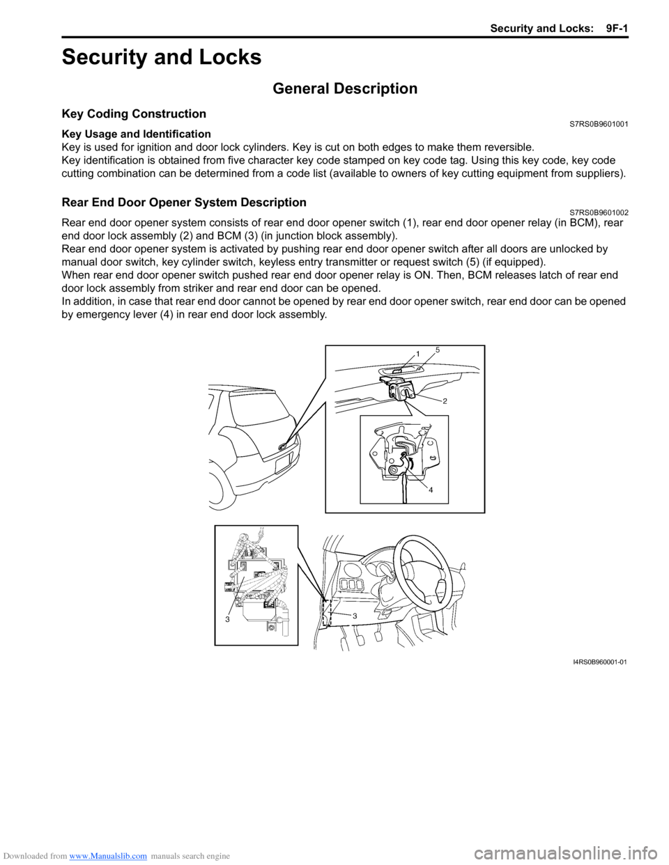
Rear end door opener system consists of rear end door opener switch (1), rear end door opener relay (in BCM), rear
end door lock assembly (2) and BCM (3) (in junction block assembly).
Rear end door opener system is activated by pushing re ar end door opener switch after all doors are unlocked by
manual door switch, key cylinder s witch, keyless entry transmitter or request switch (5) (if equipped).
When rear end door opener switch pushed rear end door opener relay is ON. Then, BCM releases latch of rear end
door lock assembly from striker and rear end door can be opened.
In addition, in case that rear end door cannot be opened by rear end door opener switch, rear end door can be opened
by emergency lever (4) in rear end door lock assembly.
I4RS0B960001-01
Page 1350 of 1496
Downloaded from www.Manualslib.com manuals search engine 9F-4 Security and Locks:
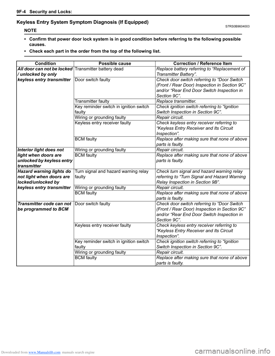
Keyless Entry System Symptom Diagnosis (If Equipped)S7RS0B9604003
NOTE
• Confirm that power door lock system is in good condition before referring to the following possible causes.
• Check each part in the order from the top of the following list.
Condition Possible cause Correction / Reference Item
All door can not be locked
/ unlocked by only
keyless entry transmitter Transmitter battery dead
Replace battery referring to “Replacement of
Transmitter Battery”.
Door switch faulty Check door switch referring to “Door Switch
(Front / Rear Door) Inspection in Section 9C”
and/or “Rear End Door Switch Inspection in
Section 9C”.
Transmitter faulty Replace transmitter.
Key reminder switch in ignition switch
faulty Check ignition switch referring to “Ignition
Switch Inspection in Section 9C”.
Wiring or grounding faulty Repair circuit.
Keyless entry receiver faulty Check keyless entry receiver referring to
“Keyless Entry Receiver and Its Circuit
Inspection”.
BCM faulty Replace after making sure that none of above
parts is faulty.
Interior light does not
light when doors are
unlocked by keyless entry
transmitter Wiring or grounding faulty
Repair circuit.
BCM faulty Replace after making sure that none of above
parts is faulty.
Hazard warning lights do
not light when doors are
locked/unlocked by
keyless entry transmitter Turn signal and hazard warning relay
faulty
Check turn signal and hazard warning relay
referring to “Turn Signal and Hazard Warning
Relay Inspection in Section 9B”.
Wiring or grounding faulty Repair circuit.
BCM faulty Replace after making sure that none of above
parts is faulty.
Transmitter code can not
be programmed to BCM Door switch faulty
Check door switch referring to “Door Switch
(Front / Rear Door) Inspection in Section 9C”
and/or “Rear End Door Switch Inspection in
Section 9C”.
Keyless entry receiver faulty Check keyless entry receiver referring to
“Keyless Entry Receiver and Its Circuit
Inspection”.
Key reminder switch in ignition switch
faulty Check ignition switch referring to “Ignition
Switch Inspection in Section 9C”.
Wiring or grounding faulty Repair circuit.
BCM faulty Replace after making sure that none of above
parts is faulty.