Page 805 of 1496

Downloaded from www.Manualslib.com manuals search engine Automatic Transmission/Transaxle: 5A-161
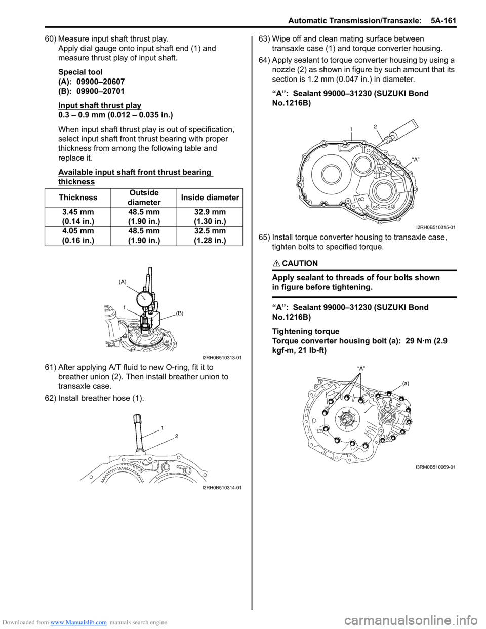
60) Measure input shaft thrust play.Apply dial gauge onto input shaft end (1) and
measure thrust play of input shaft.
Special tool
(A): 09900–20607
(B): 09900–20701
Input shaft thrust play
0.3 – 0.9 mm (0.012 – 0.035 in.)
When input shaft thrust play is out of specification,
select input shaft front th rust bearing with proper
thickness from among the following table and
replace it.
Available input shaft front thrust bearing
thickness
61) After applying A/T fluid to new O-ring, fit it to breather union (2). Then install breather union to
transaxle case.
62) Install breather hose (1). 63) Wipe off and clean mating surface between
transaxle case (1) and torque converter housing.
64) Apply sealant to torque converter housing by using a nozzle (2) as shown in figure by such amount that its
section is 1.2 mm (0.047 in.) in diameter.
“A”: Sealant 99000–31230 (SUZUKI Bond
No.1216B)
65) Install torque converter housing to transaxle case, tighten bolts to specified torque.
CAUTION!
Apply sealant to threads of four bolts shown
in figure before tightening.
“A”: Sealant 99000–31230 (SUZUKI Bond
No.1216B)
Tightening torque
Torque converter housing bolt (a): 29 N·m (2.9
kgf-m, 21 lb-ft)
Thickness
Outside
diameter Inside diameter
3.45 mm
(0.14 in.) 48.5 mm
(1.90 in.) 32.9 mm
(1.30 in.)
4.05 mm
(0.16 in.) 48.5 mm
(1.90 in.) 32.5 mm
(1.28 in.)
I2RH0B510313-01
I2RH0B510314-01
1 2
“A”
I2RH0B510315-01
I3RM0B510069-01
Page 830 of 1496

Downloaded from www.Manualslib.com manuals search engine 5B-16 Manual Transmission/Transaxle:
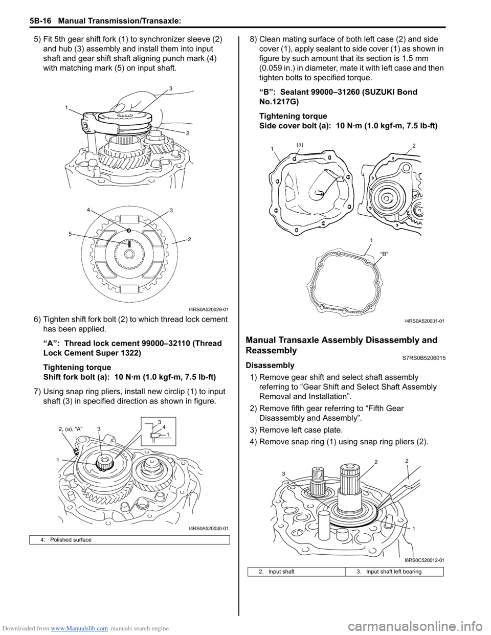
5) Fit 5th gear shift fork (1) to synchronizer sleeve (2) and hub (3) assembly and install them into input
shaft and gear shift shaft aligning punch mark (4)
with matching mark (5) on input shaft.
6) Tighten shift fork bolt (2) to which thread lock cement
has been applied.
“A”: Thread lock cement 99000–32110 (Thread
Lock Cement Super 1322)
Tightening torque
Shift fork bolt (a): 10 N·m (1.0 kgf-m, 7.5 lb-ft)
7) Using snap ring pliers, inst all new circlip (1) to input
shaft (3) in specified direction as shown in figure. 8) Clean mating surface of both left case (2) and side
cover (1), apply sealant to side cover (1) as shown in
figure by such amount t hat its section is 1.5 mm
(0.059 in.) in diameter, mate it with left case and then
tighten bolts to specified torque.
“B”: Sealant 99000–31260 (SUZUKI Bond
No.1217G)
Tightening torque
Side cover bolt (a): 10 N·m (1.0 kgf-m, 7.5 lb-ft)
Manual Transaxle Assembly Disassembly and
Reassembly
S7RS0B5206015
Disassembly
1) Remove gear shift and select shaft assembly referring to “Gear Shift an d Select Shaft Assembly
Removal and Installation”.
2) Remove fifth gear referring to “Fifth Gear Disassembly and Assembly”.
3) Remove left case plate.
4) Remove snap ring (1) using snap ring pliers (2).
4. Polished surface
I4RS0A520029-01
2, (a), “A”
1 33
4
1
I4RS0A520030-01
2. Input shaft 3. Input shaft left bearing
I4RS0A520031-01
1
2
2
3
I6RS0C520012-01
Page 853 of 1496

Downloaded from www.Manualslib.com manuals search engine Clutch: 5C-1
Transmission / Transaxle
Clutch
General Description
Clutch ConstructionS7RS0B5301001
The clutch is a diaphragm spring clutch of a dry single disc type. The diaphragm spring is of a tapering-finger type,
which is a solid ring in the outer diameter part, with a series of tapered fingers pointing inward.
The disc, carrying four torsional coil springs, is positione d on the transaxle input shaft with an involute spline fit.
The clutch cover is secured to the flywheel, and carries the diaphragm spring in such a way that the peripheral edge
part of the spring pushes on the pressure plate against the flywheel (with the disc in between), when the clutch release
bearing is held back. This is the engaged condition of the clutch.
Depressing the clutch pedal c auses the release bearing to advance and pushes on the tips of the tapered fingers of
the diaphragm spring. When this happens, the diaphragm sp ring pulls the pressure plate away from the flywheel,
thereby interrupting the flow of drive from flywheel through clutch disc to transaxle input shaft. Clutch fluid is supplied
from brake fluid reservoir. Clutch fluid level can be checked by brake fluid level of brake fluid reservoir.
[A]: For petrol engine model2. Flywheel5. Clutch cover 8. Input shaft bearing
[B]: For diesel engine model 3. Clutch disc6. Diaphragm spring 9. Input shaft
1. Crankshaft 4. Pressure plate7. Release bearing 10. Release shaft
I4RS0A530001-01
Page:
< prev 1-8 9-16 17-24