2007 SUZUKI SWIFT bearing diameter
[x] Cancel search: bearing diameterPage 347 of 1496

Downloaded from www.Manualslib.com manuals search engine Engine Mechanical: 1D-62
Undersize bearing (0.25 mm (0.0098 in.))
• 0.25 mm (0.0098 in.) undersize bearing is available, in five kinds varying in thickness.
To distinguish them, each bearing is painted in the following colors at such position as indicated in the figure.
Each color represents the following thickness at the center of bearing.
Undersize of crankshaft main bearing thickness
• If necessary, regrind crankshaft journal and sele ct undersize bearing to use with it as follows.
a. Regrind journal to the following finished diameter.
Finished journal diameter
51.7320 – 51.7500 mm (2.0367 – 2.0374 in.)
b. Using micrometer, measure regrind journal diameter. Measurement should be taken in two directions perpendicular to each other in order to check for out-of-round.
c. Using journal diameter measured above and alphabets stamped on cylinder block, select an undersize bearing
by referring to the following table.
Check bearing clearance with ne wly selected undersize bearing.
New undersize crankshaft main bearing specification
Color painted Bearing thickness
Red and Purple 2.117 – 2.121 mm (0.08335 – 0.08350 in.)
Red and Brown 2.120 – 2.124 mm (0.08347 – 0.08362 in.) Red and Green 2.123 – 2.127 mm (0.08359 – 0.08374 in.) Red and Black 2.126 – 2.130 mm (0.08371 – 0.08385 in.) Red only 2.129 – 2.133 mm (0.08382 – 0.08397 in.)
1. Paint
Measured journal diameter
51.7320 – 51.7379 mm (2.0367 – 2.0369 in.) 51.7380 – 51.7439 mm
(2.0370 – 2.0371 in.) 51.7440 – 51.7500 mm
(2.0372 – 2.0373 in.)
Alphabets stamped on cylinder block A (1) Red and Green Red and Brown Red and Purple
B (2) Red and Black Red and Green Red and Brown
C (3) Red only Red and Black Red and Green
Undersize bearing to be installed
I2RH01140192-01
I2RH0B140144-01
Page 348 of 1496
Downloaded from www.Manualslib.com manuals search engine 1D-63 Engine Mechanical:
Main Bearing Cap No.1 Bolt
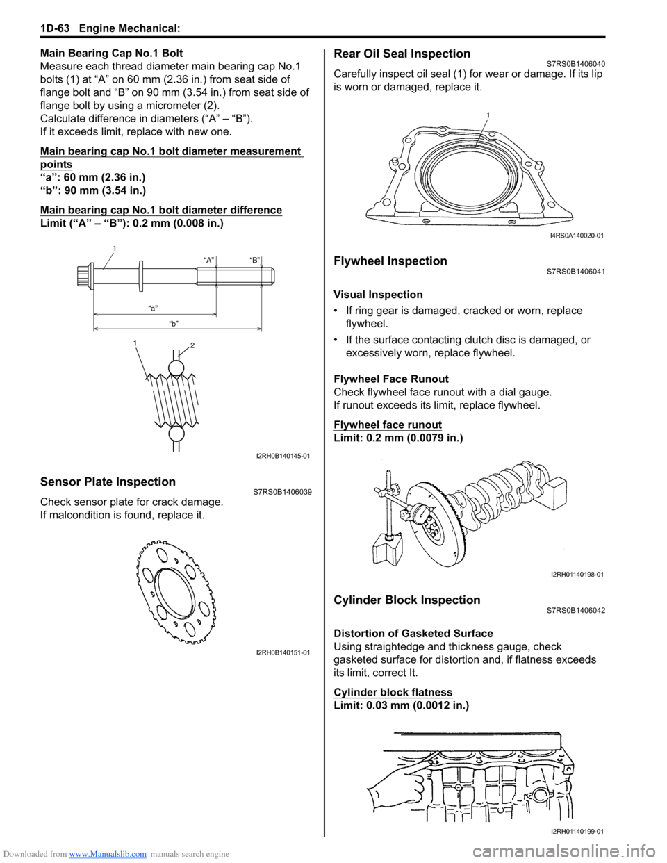
Measure each thread diameter main bearing cap No.1
bolts (1) at “A” on 60 mm (2.36 in.) from seat side of
flange bolt and “B” on 90 mm (3.54 in.) from seat side of
flange bolt by using a micrometer (2).
Calculate difference in diameters (“A” – “B”).
If it exceeds limit, replace with new one.
Main bearing cap No.1 bolt diameter measurement
points
“a”: 60 mm (2.36 in.)
“b”: 90 mm (3.54 in.)
Main bearing cap No.1 bolt diameter difference
Limit (“A” – “B”): 0.2 mm (0.008 in.)
Sensor Plate InspectionS7RS0B1406039
Check sensor plate for crack damage.
If malcondition is found, replace it.
Rear Oil Seal InspectionS7RS0B1406040
Carefully inspect oil seal (1) for wear or damage. If its lip
is worn or damaged, replace it.
Flywheel InspectionS7RS0B1406041
Visual Inspection
• If ring gear is damaged, cracked or worn, replace flywheel.
• If the surface contacting cl utch disc is damaged, or
excessively worn, replace flywheel.
Flywheel Face Runout
Check flywheel face runout with a dial gauge.
If runout exceeds its limit, replace flywheel.
Flywheel face runout
Limit: 0.2 mm (0.0079 in.)
Cylinder Block InspectionS7RS0B1406042
Distortion of Gasketed Surface
Using straightedge and thickness gauge, check
gasketed surface for distortion and, if flatness exceeds
its limit, correct It.
Cylinder block flatness
Limit: 0.03 mm (0.0012 in.)
“A”
“a” “b” “B”
1
1
2
I2RH0B140145-01
I2RH0B140151-01
I4RS0A140020-01
I2RH01140198-01
I2RH01140199-01
Page 349 of 1496
Downloaded from www.Manualslib.com manuals search engine Engine Mechanical: 1D-64
Honing or Reboring Cylinders1) When any cylinder needs reboring, all other cylinders must also be rebored at the same time.
2) Select oversized piston according to amount of cylinder wear.
Oversize piston specification
Oversize 0.50: 78.453 – 78.468 mm (3.0887 –
3.0893 in.)
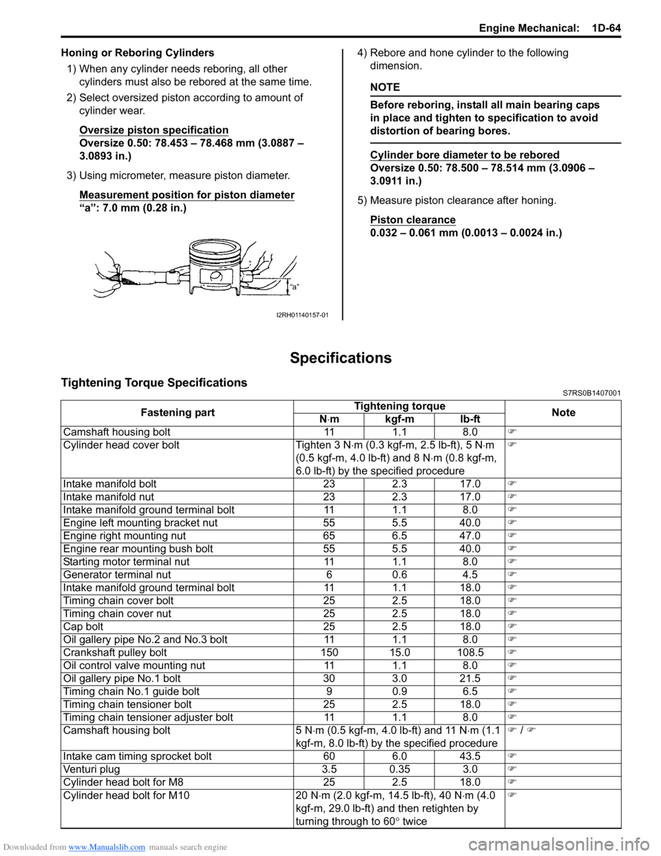
3) Using micrometer, measure piston diameter. Measurement position for piston diameter
“a”: 7.0 mm (0.28 in.) 4) Rebore and hone cylinder to the following
dimension.
NOTE
Before reboring, install all main bearing caps
in place and tighten to specification to avoid
distortion of bearing bores.
Cylinder bore diameter to be rebored
Oversize 0.50: 78.500 – 78.514 mm (3.0906 –
3.0911 in.)
5) Measure piston clearance after honing. Piston clearance
0.032 – 0.061 mm (0.0013 – 0.0024 in.)
Specifications
Tightening Torque SpecificationsS7RS0B1407001
I2RH01140157-01
Fastening part Tightening torque
Note
N ⋅mkgf-mlb-ft
Camshaft housing bolt 11 1.1 8.0 �)
Cylinder head cover bolt Tighten 3 N ⋅m (0.3 kgf-m, 2.5 lb-ft), 5 N ⋅m
(0.5 kgf-m, 4.0 lb-ft) and 8 N ⋅m (0.8 kgf-m,
6.0 lb-ft) by the specified procedure �)
Intake manifold bolt 23 2.3 17.0 �)
Intake manifold nut 23 2.3 17.0 �)
Intake manifold ground terminal bolt 11 1.1 8.0 �)
Engine left mounting bracket nut 55 5.5 40.0 �)
Engine right mounting nut 65 6.5 47.0 �)
Engine rear mounting bush bolt 55 5.5 40.0 �)
Starting motor terminal nut 11 1.1 8.0 �)
Generator terminal nut 6 0.6 4.5 �)
Intake manifold ground terminal bolt 11 1.1 18.0 �)
Timing chain cover bolt 25 2.5 18.0 �)
Timing chain cover nut 25 2.5 18.0 �)
Cap bolt 25 2.5 18.0 �)
Oil gallery pipe No.2 and No.3 bolt 11 1.1 8.0 �)
Crankshaft pulley bolt 150 15.0 108.5 �)
Oil control valve mounting nut 11 1.1 8.0 �)
Oil gallery pipe No.1 bolt 30 3.0 21.5 �)
Timing chain No.1 guide bolt 9 0.9 6.5 �)
Timing chain tensioner bolt 25 2.5 18.0 �)
Timing chain tensioner adjuster bolt 11 1.1 8.0 �)
Camshaft housing bolt 5 N ⋅m (0.5 kgf-m, 4.0 lb-ft) and 11 N ⋅m (1.1
kgf-m, 8.0 lb-ft) by the specified procedure �)
/ �)
Intake cam timing sprocket bolt 60 6.0 43.5 �)
Venturi plug 3.5 0.35 3.0 �)
Cylinder head bolt for M8 25 2.5 18.0 �)
Cylinder head bolt for M10 20 N ⋅m (2.0 kgf-m, 14.5 lb-ft), 40 N ⋅m (4.0
kgf-m, 29.0 lb-ft) and then retighten by
turning through to 60 ° twice �)
Page 469 of 1496

Downloaded from www.Manualslib.com manuals search engine Wheels and Tires: 2D-2
Lower than recommended pressure can cause:
• Tire squeal on turns
• Hard Steering
• Rapid and uneven wear on the edges of the tread
• Tire rim bruises and rupture
• Tire cord breakage
• High tire temperature
• Reduced handling
• High fuel consumption
Replacement Tires
When replacement is necessary, the original equipment
type tire should be used. Refer to the Tire Placard.
Replacement tires should be of the same size, load
range and construction as those originally on the vehicle.
Use of any other size or type tire may affect ride,
handling, speedometer / odometer calibration, vehicle
ground clearance and tire or snow chain clearance to the
body and chassis.
It is recommended that new tires be installed in pairs on
the same axle. If necessary to replace only one tire, it
should be paired with the tire having the most tread, to
equalize braking traction.
WARNING!
Do not mix different types of tires on the
same vehicle such as radial, bias and bias-
belted tires except in emergencies, because
handling may be seriously affected and may
result in loss of control.
The metric term for tire infl ation pressure is the kilo
pascal (kPa). Tire pressures is usually printed in both
kPa and kgf/cm
2 on the “Tire Placard”.
Metric tire gauges are available from tool suppliers.
The chart, shown the table, converts commonly used
inflation pressures from kPa to kgf/cm
2 and psi.
Wheels DescriptionS7RS0B2401002
Wheel Maintenance
Wheel repairs that use welding, heating, or peening are
not approved. All damaged wheels should be replaced.
Replacement Wheels
Wheels must be replaced if they are bent, dented, have
excessive lateral or radial runout, air leak through welds,
have elongated bolt holes, if lug wheel bolts won’t stay
tight, or if they are heavily rusted. Wheels with greater
runout than shown in the following may cause
objectional vibrations.
Replacement wheels must be equivalent to the original
equipment wheels in load capacity, diameter, rim with
offset and mounting configuration. A wheel of improper
size or type may affect wheel and bearing life, brake
cooling, speedometer / odometer calibration, vehicle
ground clearance and tire clearance to body and
chassis.
How to Measure Wheel Runout
To measure the wheel runout, it is necessary to use an
accurate dial indicator. The tire may be on or off the
wheel. The wheel should be installed to the wheel
balancer of the like for proper measurement.
Take measurements of both lateral runout “a” and radial
runout “b” at both inside an d outside of the rim flange.
With the dial indicator set in place securely, turn the
wheel one full revolution slowly and record every reading
of the indicator.
When the measured runout exceeds the specification
and correction by the balancer adjustment is impossible,
replace the wheel. If the reading is affected by welding,
paint or scratch, it should be ignored.
Lateral runout limit “a”
: 0.3 mm (0.012 in.)
Radial runout limit “b”
: 0.3 mm (0.012 in.)
kPa kgf/cm2psi
Conversion: 1 psi =
6.895 kPa 1 kgf/cm
2 =
98.066 kPa 160 1.6 23
180 1.8 26
200 2.0 29
220 2.2 32
240 2.4 35
260 2.6 38
280 2.8 41
300 3.0 44
I4RS0A240001-01
Page 764 of 1496

Downloaded from www.Manualslib.com manuals search engine 5A-120 Automatic Transmission/Transaxle:
67) Screwing 3 bolts (1), remove reduction drive gear (2).
CAUTION!
Screw 3 bolts into reduction drive gear
uniformly, or reduction drive gear, bearing
and transaxle case may be damaged.
Bolt length
35 mm (1.38 in.)
68) Blowing compressed air from oil hole (1) of oil pump,
remove 1st and reverse brake piston (2). 69) Remove parking lock pawl bracket (1).
70) With slotted screwdriver, cut and unfold manual
valve lever spacer (1) and proceed to remove
manual valve lever spacer.
71) Using spring pin remover with 3.5 mm (0.14 in.) in diameter and hammer, drive out manual valve lever
pin (1).
72) Remove manual shift shaft (2).
73) Remove parking lock pawl rod (2) from manual valve lever (1).
I2RH0B510140-01
1 2I4RS0A510040-01
I2RH0B510142-01
I2RH0B510143-01
I2RH0B510144-01
I2RH0B510145-01
Page 794 of 1496
Downloaded from www.Manualslib.com manuals search engine 5A-150 Automatic Transmission/Transaxle:
Automatic Transaxle Unit AssemblyS7RS0B5106060
CAUTION!
• Automatic transaxle consists of highly precise parts. As even flaw in small part
may cause oil leakage or decrease in
function, check each part carefully before
installation.
• Clean all parts with compressed air. Never use wiping cloths or rags.
• Before assembling new clutch or brake discs, soak them in automatic transaxle
fluid for at least 2 hours.
• Be sure to use new gaskets and O-rings.
• Lubricate O-rings with automatic transaxle
fluid.
• Apply automatic transaxle fluid on sliding or rotating surfaces of the parts before
assembly.
• Use Suzuki Super Grease “C” to retain parts in place.
• Be sure to install thrust bearings and races in correct direction and position.
• Make sure that snap ring ends are not aligned with one of cut outs and are
installed in groove correctly.
• Do not use adhesive cements on gaskets and similar parts.
• Be sure to torque each bolt and nut to specification.
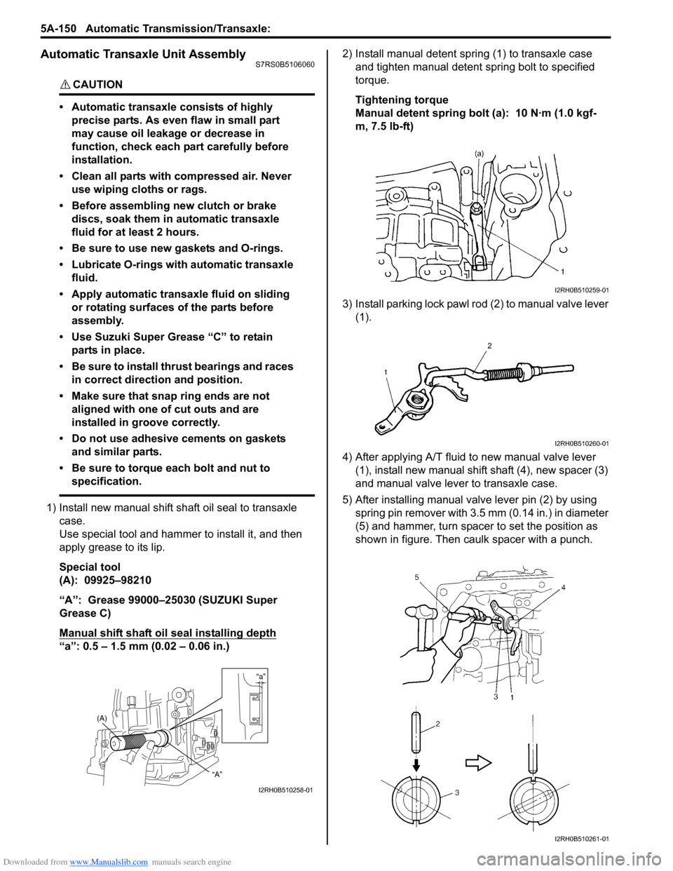
1) Install new manual shift sh aft oil seal to transaxle
case.
Use special tool and hammer to install it, and then
apply grease to its lip.
Special tool
(A): 09925–98210
“A”: Grease 99000–25030 (SUZUKI Super
Grease C)
Manual shift shaft oil seal installing depth
“a”: 0.5 – 1.5 mm (0.02 – 0.06 in.) 2) Install manual detent spring (1) to transaxle case
and tighten manual detent spring bolt to specified
torque.
Tightening torque
Manual detent spring bolt (a): 10 N·m (1.0 kgf-
m, 7.5 lb-ft)
3) Install parking lock pawl ro d (2) to manual valve lever
(1).
4) After applying A/T fluid to new manual valve lever (1), install new manual shift shaft (4), new spacer (3)
and manual valve lever to transaxle case.
5) After installing manual valve lever pin (2) by using spring pin remover with 3.5 mm (0.14 in.) in diameter
(5) and hammer, turn spacer to set the position as
shown in figure. Then caulk spacer with a punch.
“a”
(A)
“A”
I2RH0B510258-01
I2RH0B510259-01
I2RH0B510260-01
I2RH0B510261-01
Page 801 of 1496
Downloaded from www.Manualslib.com manuals search engine Automatic Transmission/Transaxle: 5A-157
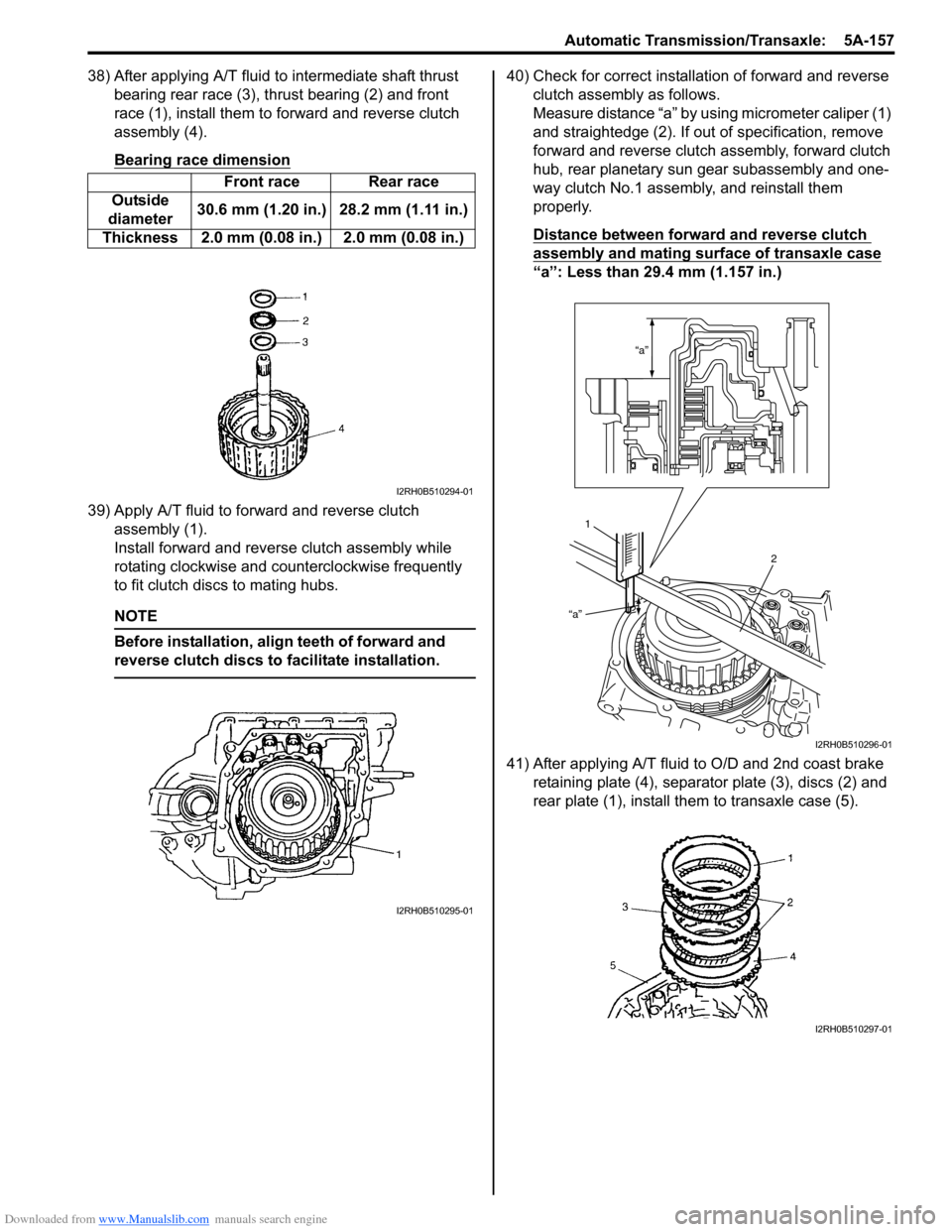
38) After applying A/T fluid to intermediate shaft thrust bearing rear race (3), thrust bearing (2) and front
race (1), install them to forward and reverse clutch
assembly (4).
Bearing race dimension
39) Apply A/T fluid to forward and reverse clutch assembly (1).
Install forward and revers e clutch assembly while
rotating clockwise and co unterclockwise frequently
to fit clutch discs to mating hubs.
NOTE
Before installation, align teeth of forward and
reverse clutch discs to facilitate installation.
40) Check for correct installation of forward and reverse clutch assembly as follows.
Measure distance “a” by using micrometer caliper (1)
and straightedge (2). If out of specification, remove
forward and reverse clutch assembly, forward clutch
hub, rear planetary sun gear subassembly and one-
way clutch No.1 assemb ly, and reinstall them
properly.
Distance between forward and reverse clutch
assembly and mating surface of transaxle case
“a”: Less than 29.4 mm (1.157 in.)
41) After applying A/T fluid to O/D and 2nd coast brake retaining plate (4), separator plate (3), discs (2) and
rear plate (1), install th em to transaxle case (5).
Front race Rear race
Outside
diameter 30.6 mm (1.20 in.) 28.2 mm (1.11 in.)
Thickness 2.0 mm (0.08 in.) 2.0 mm (0.08 in.)
I2RH0B510294-01
I2RH0B510295-01
“a”
“a”
1 2
I2RH0B510296-01
I2RH0B510297-01
Page 802 of 1496
Downloaded from www.Manualslib.com manuals search engine 5A-158 Automatic Transmission/Transaxle:
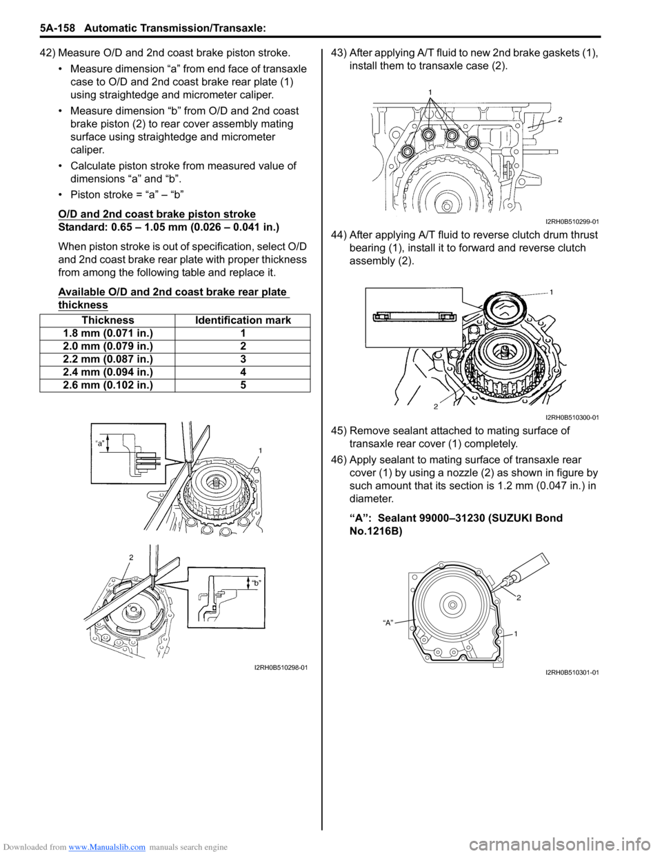
42) Measure O/D and 2nd coast brake piston stroke.• Measure dimension “a” from end face of transaxle case to O/D and 2nd coast brake rear plate (1)
using straightedge and micrometer caliper.
• Measure dimension “b” from O/D and 2nd coast brake piston (2) to rear cover assembly mating
surface using straightedge and micrometer
caliper.
• Calculate piston stroke from measured value of dimensions “a” and “b”.
• Piston stroke = “a” – “b”
O/D and 2nd coast brake piston stroke
Standard: 0.65 – 1.05 mm (0.026 – 0.041 in.)
When piston stroke is out of specification, select O/D
and 2nd coast brake rear plate with proper thickness
from among the following table and replace it.
Available O/D and 2nd coast brake rear plate
thickness
43) After applying A/T fluid to new 2nd brake gaskets (1), install them to transaxle case (2).
44) After applying A/T fluid to reverse clutch drum thrust bearing (1), install it to forward and reverse clutch
assembly (2).
45) Remove sealant attached to mating surface of transaxle rear cover (1) completely.
46) Apply sealant to mating surface of transaxle rear cover (1) by using a nozzle (2) as shown in figure by
such amount that its section is 1.2 mm (0.047 in.) in
diameter.
“A”: Sealant 99000–31230 (SUZUKI Bond
No.1216B)
Thickness Identification mark
1.8 mm (0.071 in.) 1
2.0 mm (0.079 in.) 2
2.2 mm (0.087 in.) 3
2.4 mm (0.094 in.) 4
2.6 mm (0.102 in.) 5
I2RH0B510298-01
I2RH0B510299-01
I2RH0B510300-01
“A” 2
1
I2RH0B510301-01