2007 SUZUKI SWIFT Steering knuckle
[x] Cancel search: Steering knucklePage 523 of 1496

Downloaded from www.Manualslib.com manuals search engine Front Brakes: 4B-7
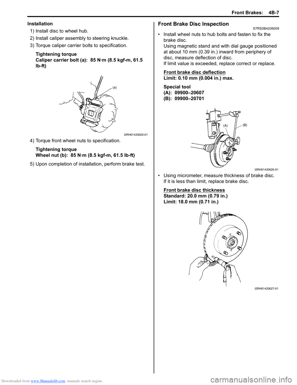
Installation1) Install disc to wheel hub.
2) Install caliper assemb ly to steering knuckle.
3) Torque caliper carrier bolts to specification.
Tightening torque
Caliper carrier bolt (a): 85 N·m (8.5 kgf-m, 61.5
lb-ft)
4) Torque front wheel nuts to specification. Tightening torque
Wheel nut (b): 85 N·m (8.5 kgf-m, 61.5 lb-ft)
5) Upon completion of installation, perform brake test.Front Brake Disc InspectionS7RS0B4206009
• Install wheel nuts to hub bolts and fasten to fix the brake disc.
Using magnetic stand and with dial gauge positioned
at about 10 mm (0.39 in.) inward from periphery of
disc, measure deflection of disc.
If limit value is exceeded, replace correct or replace.
Front brake disc deflection
Limit: 0.10 mm (0.004 in.) max.
Special tool
(A): 09900–20607
(B): 09900–20701
• Using micrometer, measure thickness of brake disc. If it is less than limit, replace brake disc.
Front brake disc thickness
Standard: 20.0 mm (0.79 in.)
Limit: 18.0 mm (0.71 in.)
I2RH01420028-01
I2RH01420026-01
I2RH01420027-01
Page 573 of 1496

Downloaded from www.Manualslib.com manuals search engine ABS: 4E-34
Rear Wheel Speed Sensor InspectionS7RS0B4506009
Refer to “Front Wheel Speed Sensor Inspection” since
rear wheel speed sensor is the same as front wheel
speed sensor.
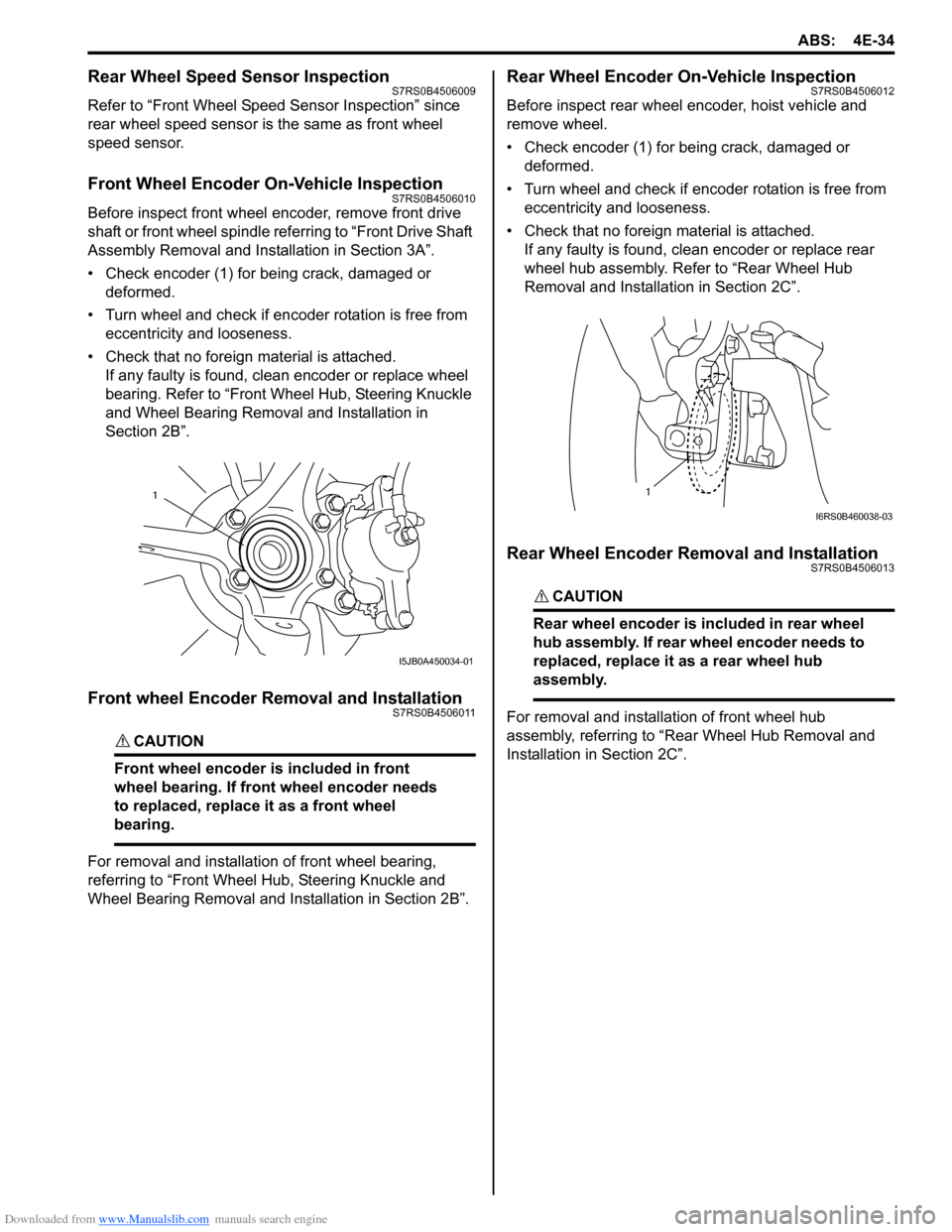
Front Wheel Encoder On-Vehicle InspectionS7RS0B4506010
Before inspect front wheel encoder, remove front drive
shaft or front wheel spindle referring to “Front Drive Shaft
Assembly Removal and Installation in Section 3A”.
• Check encoder (1) for being crack, damaged or deformed.
• Turn wheel and check if encoder rotation is free from eccentricity and looseness.
• Check that no foreign material is attached. If any faulty is found, cl ean encoder or replace wheel
bearing. Refer to “Front Wheel Hub, Steering Knuckle
and Wheel Bearing Removal and Installation in
Section 2B”.
Front wheel Encoder Removal and InstallationS7RS0B4506011
CAUTION!
Front wheel encoder is included in front
wheel bearing. If front wheel encoder needs
to replaced, replace it as a front wheel
bearing.
For removal and installation of front wheel bearing,
referring to “Front Wheel Hub, Steering Knuckle and
Wheel Bearing Removal and Installation in Section 2B”.
Rear Wheel Encoder On-Vehicle InspectionS7RS0B4506012
Before inspect rear wheel encoder, hoist vehicle and
remove wheel.
• Check encoder (1) for being crack, damaged or deformed.
• Turn wheel and check if encoder rotation is free from eccentricity and looseness.
• Check that no foreign material is attached. If any faulty is found, clean encoder or replace rear
wheel hub assembly. Refer to “Rear Wheel Hub
Removal and Installati on in Section 2C”.
Rear Wheel Encoder Removal and InstallationS7RS0B4506013
CAUTION!
Rear wheel encoder is included in rear wheel
hub assembly. If rear wheel encoder needs to
replaced, replace it as a rear wheel hub
assembly.
For removal and installation of front wheel hub
assembly, referring to “Rear Wheel Hub Removal and
Installation in Section 2C”.
1
I5JB0A450034-01
1
I6RS0B460038-03
Page 635 of 1496

Downloaded from www.Manualslib.com manuals search engine Electronic Stability Program: 4F-61
Front Wheel Encoder On-Vehicle InspectionS7RS0B4606033
Before inspect front wheel encoder, remove front drive
shaft or front wheel spindle referring to “Front Drive Shaft
Assembly Removal and Installation in Section 3A”.
• Check encoder (1) for being crack, damaged or deformed.
• Turn wheel and check if encoder rotation is free from eccentricity and looseness.
• Check that no foreign material is attached. If any faulty is found, cl ean encoder or replace wheel
bearing. Refer to “Front Wheel Hub, Steering Knuckle
and Wheel Bearing Removal and Installation in
Section 2B”.
Front Wheel Encoder Removal and InstallationS7RS0B4606034
CAUTION!
Front wheel encoder is included in front
wheel bearing. If front wheel encoder needs
to replaced, replace it as a front wheel
bearing.
For removal and installation of front wheel bearing,
referring to “Front Wheel Hub, Steering Knuckle and
Wheel Bearing Removal and Installation in Section 2B”.
Rear Wheel Encoder On-Vehicle InspectionS7RS0B4606035
Before inspect rear wheel encoder, hoist vehicle and
remove wheel.
• Check encoder (1) for being crack, damaged or deformed.
• Turn wheel and check if encoder rotation is free from eccentricity and looseness.
• Check that no foreign material is attached. If any faulty is found, cl ean encoder or replace rear
wheel hub assembly. Refer to “Rear Wheel Hub
Removal and Installati on in Section 2C”.
Rear Wheel Encoder Removal and InstallationS7RS0B4606036
CAUTION!
Rear wheel encoder is included in rear wheel
hub assembly. If rear wheel encoder needs to
replaced, replace it as a rear wheel hub
assembly.
For removal and installation of front wheel hub
assembly, referring to “Rear Wheel Hub Removal and
Installation in Section 2C”.
Master Cylinder Pressure Sensor On-Vehicle
Inspection
S7RS0B4606016
1) Calibrate yaw rate / G sens or assembly referring to
“Sensor Calibration”.
2) Check that basic brake system other than ESP ®
refer to “Brakes Diagnosi s Note in Section 4A”.
3) Connect SUZUKI scan tool to data link connector (DLC) (1) with ignition switch OFF.
Special tool
(A): SUZUKI scan tool
1
I5JB0A450034-01
1
I6RS0B460038-03
(A)
1
I4RS0B450003-01
Page 747 of 1496

Downloaded from www.Manualslib.com manuals search engine Automatic Transmission/Transaxle: 5A-103
Installation
Reverse removal procedure noting the following.
• Connect TCM connectors securely.
• If the vehicle is equipped with air bag system, be sure to enable air bag system after TCM is back in place.
Refer to “Enabling Air Bag System in Section 8B”.
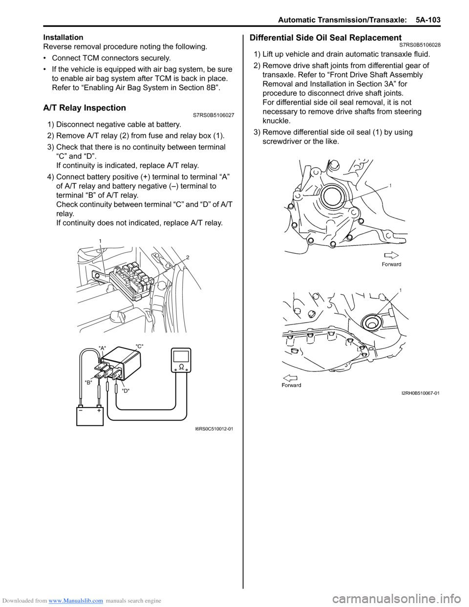
A/T Relay InspectionS7RS0B5106027
1) Disconnect negative cable at battery.
2) Remove A/T relay (2) from fuse and relay box (1).
3) Check that there is no continuity between terminal “C” and “D”.
If continuity is indicated, replace A/T relay.
4) Connect battery positive (+ ) terminal to terminal “A”
of A/T relay and battery negative (–) terminal to
terminal “B” of A/T relay.
Check continuity between terminal “C” and “D” of A/T
relay.
If continuity does not indicated, replace A/T relay.
Differential Side Oil Seal ReplacementS7RS0B5106028
1) Lift up vehicle and drain automatic transaxle fluid.
2) Remove drive shaft joints from differential gear of transaxle. Refer to “Front Drive Shaft Assembly
Removal and Installation in Section 3A” for
procedure to disconnect drive shaft joints.
For differential side oil seal removal, it is not
necessary to remove drive shafts from steering
knuckle.
3) Remove differential side oil seal (1) by using screwdriver or the like.
"D"
"B" "A"
"C"
1
2
I6RS0C510012-01
I2RH0B510067-01
Page 923 of 1496

Downloaded from www.Manualslib.com manuals search engine Power Assisted Steering System: 6C-41
Tie-Rod End Boot On-Vehicle InspectionS7RS0B6306002
Check boot for crack and damage.
If any defect is found, replace it with a new one.
Tie-Rod End Removal and InstallationS7RS0B6306003
Removal1) Hoist vehicle, and then remove wheel referring to “Wheel Removal and Installation in Section 2D”.
2) Remove split pin (2) and tie-rod end nut (1) from steering knuckle.
3) Disconnect tie-rod end (1) from knuckle (2) using puller (3). 4) For ease of adjustment after installation, make
marking (1) of tie-rod end lock nut (2) position on tie-
rod end thread. Then, loosen lock nut and remove
tie-rod end (3) from tie-rod (4).
Installation 1) Install tie-rod end lock nut (1) and tie-rod end (2) to tie-rod (3). Align lock nut with mark (4) on tie-rod
thread.
9. Tie-rod end nut 20. Gear rack side No.2 bracket : 9.5 N⋅m (0.95 kgf-m, 7.0 lb-ft)
10. Steering gear case mounting No.1 bolt 21. Steering gear case mounting No.2 bolt : Do not reuse.
11. Steering gear case grommet 22. Clip
I3RM0A630024-01
21
I7RS0A630016-01
2 1
3
I4RS0A630040-01
I4RS0A630041-01
I4RS0A630042-01
Page 924 of 1496

Downloaded from www.Manualslib.com manuals search engine 6C-42 Power Assisted Steering System:
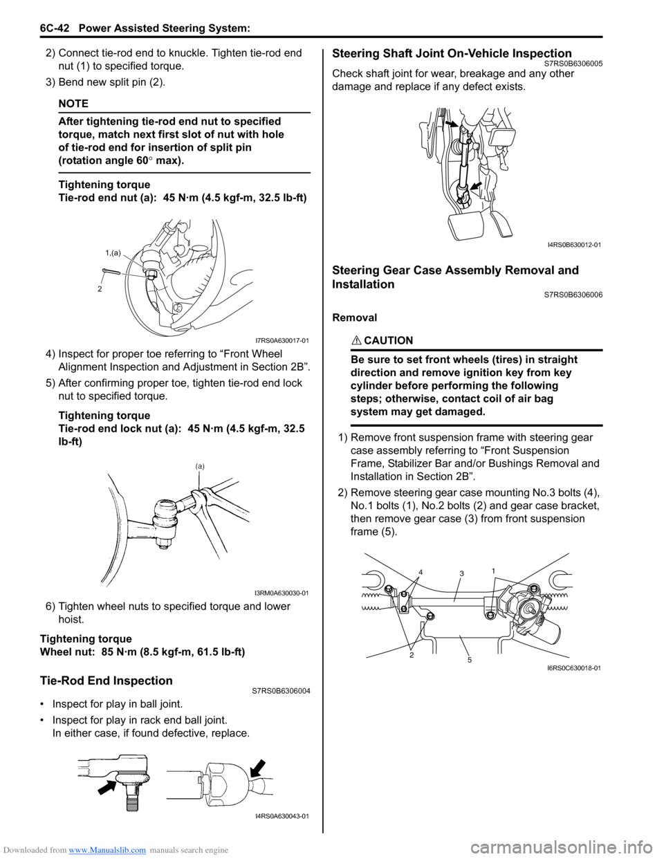
2) Connect tie-rod end to knuckle. Tighten tie-rod end nut (1) to spec ified torque.
3) Bend new split pin (2).
NOTE
After tightening tie-rod end nut to specified
torque, match next first slot of nut with hole
of tie-rod end for insertion of split pin
(rotation angle 60 ° max).
Tightening torque
Tie-rod end nut (a): 45 N·m (4.5 kgf-m, 32.5 lb-ft)
4) Inspect for proper toe re ferring to “Front Wheel
Alignment Inspection and Adjustment in Section 2B”.
5) After confirming proper toe, tighten tie-rod end lock nut to specified torque.
Tightening torque
Tie-rod end lock nut (a): 45 N·m (4.5 kgf-m, 32.5
lb-ft)
6) Tighten wheel nuts to specified torque and lower hoist.
Tightening torque
Wheel nut: 85 N·m (8.5 kgf-m, 61.5 lb-ft)
Tie-Rod End InspectionS7RS0B6306004
• Inspect for play in ball joint.
• Inspect for play in rack end ball joint. In either case, if found defective, replace.
Steering Shaft Joint On-Vehicle InspectionS7RS0B6306005
Check shaft joint for wear, breakage and any other
damage and replace if any defect exists.
Steering Gear Case Assembly Removal and
Installation
S7RS0B6306006
Removal
CAUTION!
Be sure to set front wheels (tires) in straight
direction and remove ignition key from key
cylinder before performing the following
steps; otherwise, contact coil of air bag
system may get damaged.
1) Remove front suspension frame with steering gear case assembly referrin g to “Front Suspension
Frame, Stabilizer Bar and/ or Bushings Removal and
Installation in Section 2B”.
2) Remove steering gear case mounting No.3 bolts (4), No.1 bolts (1), No.2 bolts (2) and gear case bracket,
then remove gear case (3) from front suspension
frame (5).
2 1,(a)
I7RS0A630017-01
I3RM0A630030-01
I4RS0A630043-01
I4RS0B630012-01
25
3
14
I6RS0C630018-01