Page 1275 of 1496
Downloaded from www.Manualslib.com manuals search engine Wiring Systems: 9A-104
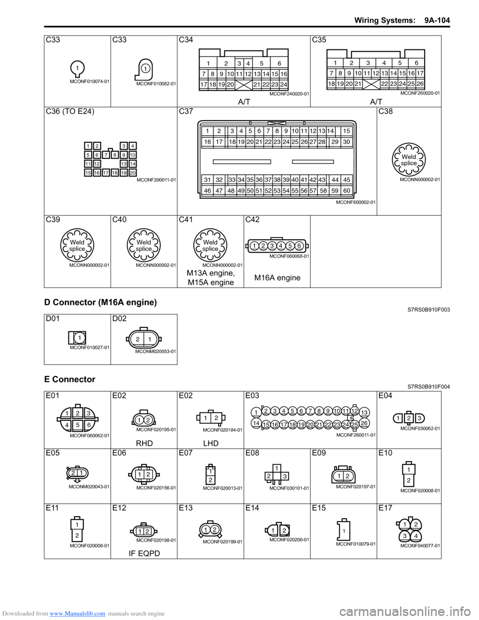
D Connector (M16A engine)S7RS0B910F003
E ConnectorS7RS0B910F004
C33C33C34 C35
A/T A/T
C36 (TO E24) C37 C38
C39 C40C41 C42
M13A engine, M15A engine M16A engine
D01 D02
E01 E02E02E03 E04
RHD LHD
E05 E06E07E08 E09E10
E11 E12E13 E14 E15 E17
IF EQPD
1
MCONF010074-01
1
MCONF010082-0117181920
7
1256
89101113141516
21222324
12
34
MCONF240020-01
181920 21
7 12345 68910
22232425
13141516
26
171112
MCONF260020-01
21
8
3
9765
131211
1819
4
10
14
20171615MCONF200011-01
12 3456
20 21
16 17 18 1978910
22 23 24 25 12
272613
28
31 32 33 34 35 36 50 51
46 47 48 49 37 38 39 40
52 53 54 5511
41
56
42
5743
5814 15 29 30
44 60 45
59
MCONF600002-01
Weld
splice
MCONN000002-01
Weld
splice
MCONN000002-01
Weld
splice
MCONN000002-01
Weld
splice
MCONN000002-01
1234 56
MCONF060068-01
1
MCONF010027-01
21
MCONM020053-01
1 2 3
4 5
6
MCONF060062-01
12
MCONF020195-01
12
MCONF020184-01
12345678910111213
14151617181920212223242526
MCONF260011-01
123
MCONF030062-01
21
MCONM020043-01
12
MCONF020156-01
1
2
MCONF020013-01
12 3
MCONF030101-01
21
MCONF020197-01
1
2
MCONF020008-01
1
2
MCONF020008-01
21
MCONF020198-01
12
MCONF020199-01
1
2
MCONF020200-01
1
MCONF010079-01
21
43
MCONF040077-01
Page 1277 of 1496
Downloaded from www.Manualslib.com manuals search engine Wiring Systems: 9A-106
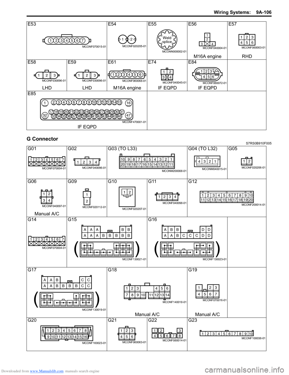
G ConnectorS7RS0B910F005
E53E54E55 E56E57
M16A engine RHD
E58 E59E61E74 E84
LHD LHD M16A engine IF EQPD IF EQPD
E85
IF EQPD
G01 G02G03 (TO L33) G04 (TO L32) G05
G06 G09G10G11G12
Manual A/C
G14 G15 G16
G17 G18G19
Manual A/C Manual A/C
G20 G21G22G23
1234567
MCONF070015-01
12
MCONF020205-01
Weld
splice
MCONN000002-01
1
2
34
MCONF040004-01
123
46 5
MCONF060003-01
1 23
MCONF030096-01
123
MCONF030096-01
1234 56
MCONF060068-01
1
34
2
MCONF040045-01
2
5
46
13
MCONF060072-01
21
3247
163451213141567891011
3334353643444546373839404142181719202128293031222324252627
MCONF470001-01
1234567
MCONF070004-01
1234
MCONF040096-01
54 32 167910
20 19 18 17 16 15 14 13 12 118
MCONM200008-01
12
34
MCONM040015-01
12
MCONF020206-01
12
34
MCONF040097-01
1
2
MCONF020112-01
21
MCONF020207-01
1234
MCONF040098-01
125678911 12 13 14 15 16 17 18 1910
2034
MCONF200014-01
1234567
MCONF070004-01
AAA BB
AAA B
BB
BB
( )
MCONF130021-01
ABB DD
AAB D
CC
CD
( )
MCONF130023-01
AAB CC
AAB C
BB
BC
( )
MCONF130019-01
123
78910
456
11121314
MCONF140018-01
3
7654
21
MCONF070016-01
1234567 8
9 10111213141516
MCONF160023-01
3
21
654
MCONF060063-01
2
51
47 6
8
3
MCONF080014-01
12345678910MCONF100038-01
Page 1279 of 1496
Downloaded from www.Manualslib.com manuals search engine Wiring Systems: 9A-108
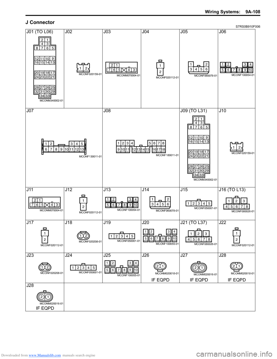
J ConnectorS7RS0B910F006
J01 (TO L06) J02J03J04J05J06
J07 J08J09 (TO L31) J10
J11 J12J13J14 J15 J16 (TO L13)
J17 J18J19 J20 J21 (TO L37) J22
J23 J24J25 J26 J27 J28
IF EQPD IF EQPD IF EQPD
J28
IF EQPD
313234 33 30 29
24
28 23
27 22
26 21
25
16
20 19 15
12 11 10
14
1813
17
87 6
2
4
1
3
5
9
MCONM340002-01
21
MCONF020159-016
21
7543
MCONM070004-01
1
2
MCONF020112-01
12
3456
MCONF060078-01
1234
5678910
MCONF100054-01
135
68910111324
712
MCONF130011-01
1234
91011
5678
12131415161718
MCONF180011-01
3132 34 33 30 29
24
28 23
27 22
26 21
25
16
20 19 15
12 11 10
14
1813
17
87 6
2
4
1
3
5
9
MCONM340002-01
21
MCONF020159-01
6
21
7543
MCONM070004-01
1
2
MCONF020112-01
1234
5678910
MCONF100054-01
12
3456
MCONF060078-01
12345MCONF050001-0187654
231
MCONF080026-01
1
2
MCONF020112-01
2
1
MCONF020208-01
12345MCONF050001-01
2
1 4
3
7 9
65 108
MCONF100055-0187654
231
MCONF080026-01
1
2
MCONF020112-01
2
1
MCONF020208-01
12345MCONF050001-01
2
1 4
3
7 9
65 108
MCONF100055-01
12
MCONM020018-01
2
1
MCONM020016-01
12
MCONM020018-01
21
MCONM020016-01
Page 1280 of 1496
Downloaded from www.Manualslib.com manuals search engine 9A-109 Wiring Systems:
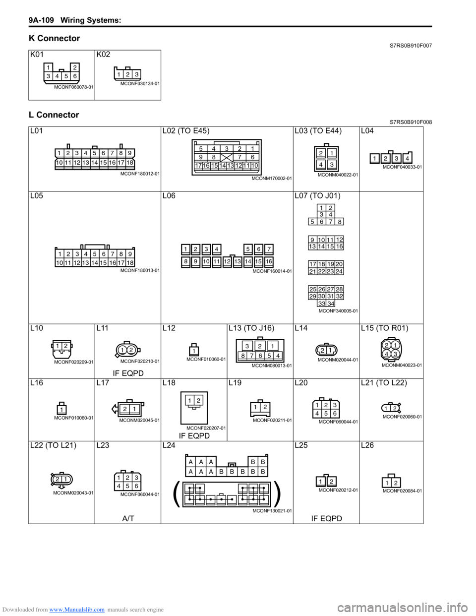
K ConnectorS7RS0B910F007
L ConnectorS7RS0B910F008
K01K02
L01 L02 (TO E45)L03 (TO E44) L04
L05 L06L07 (TO J01)
L10 L11L12L13 (TO J16) L14 L15 (TO R01)
IF EQPD
L16 L17L18L19L20 L21 (TO L22)
IF EQPD
L22 (TO L21) L23 L24L25L26
A/T IF EQPD
12
3456
MCONF060078-01
123
MCONF030134-01
123456789
101112131415161718
MCONF180012-01175
9161312 11 101514
4
832
71
6
MCONM170002-01
21
43
MCONM040022-01
2341
MCONF040033-01
123456789
15 16 17 18
1110 12 13 14
MCONF180013-01
4
3
56
1214
11
10 15
721
13
16
98
MCONF160014-01
31 32
3433
30
29
24
28
23
27
22
26
21
25
13 2019
14
91011
15
18 16
17 7
1
3
2
4
56 8
12
MCONF340005-01
12
MCONF020209-01
1 2
MCONF020210-01
1MCONF010060-0145678
213
MCONM080013-01
21
MCONM020044-01
2
4 1
3
MCONM040023-01
1MCONF010060-01
12
MCONM020045-01
21
MCONF020207-01
12
MCONF020211-01
1 23
456
MCONF060044-01
12
MCONF020060-01
21
MCONM020043-01
1 23
456
MCONF060044-01
AAA BB
AAA B
BB
BB
( )
MCONF130021-01
12
MCONF020212-0121MCONF020084-01
Page 1282 of 1496
Downloaded from www.Manualslib.com manuals search engine 9A-111 Wiring Systems:
M Connector (SPORT model)S7RS0B910F009
O ConnectorS7RS0B910F010
R ConnectorS7RS0B910F011
M01 (TO L70) M02M03M04M05
O01 (TO L42) O02 O03O04 O05 O06
R01 (TO L15) R02
1
3 2
4
MCONF040123-01
1
2
MCONF020013-01
1
2
MCONF020013-01
1 2
MCONF020277-01
12
MCONF020277-01
3
2
1
45678
MCONF080027-01
1
MCONM010034-01
12
34
MCONF040012-01
12
34
MCONF040143-01
12
34
MCONF040095-01
1
MCONM010034-01
1
3 2
4
MCONF040100-01
1 2
34
MCONF040101-01
Page 1313 of 1496
Downloaded from www.Manualslib.com manuals search engine Instrumentation / Driver Info. / Horn: 9C-18
Instrument Panel Removal and InstallationS7RS0B9306015
WARNING!
Refer to “Air Bag Warning in Section 00”
before starting service work.
Removal
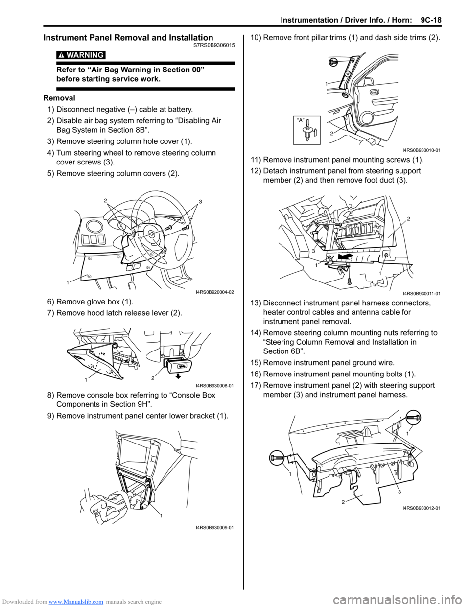
1) Disconnect negative (–) cable at battery.
2) Disable air bag system referring to “Disabling Air Bag System in Section 8B”.
3) Remove steering column hole cover (1).
4) Turn steering wheel to remove steering column cover screws (3).
5) Remove steering column covers (2).
6) Remove glove box (1).
7) Remove hood latch release lever (2).
8) Remove console box referring to “Console Box Components in Section 9H”.
9) Remove instrument panel center lower bracket (1). 10) Remove front pillar trims
(1) and dash side trims (2).
11) Remove instrument panel mounting screws (1).
12) Detach instrument panel from steering support member (2) and then remove foot duct (3).
13) Disconnect instrument panel harness connectors, heater control cables and antenna cable for
instrument panel removal.
14) Remove steering column mounting nuts referring to “Steering Column Remova l and Installation in
Section 6B”.
15) Remove instrument panel ground wire.
16) Remove instrument panel mounting bolts (1).
17) Remove instrument panel (2) with steering support member (3) and instrument panel harness.
1
32
I4RS0B920004-02
2
1I4RS0B930008-01
1
I4RS0B930009-01
“A”
“A”
1
2
I4RS0B930010-01
1
1 2
3
I4RS0B930011-01
1 1
2
3I4RS0B930012-01
Page 1314 of 1496
Downloaded from www.Manualslib.com manuals search engine 9C-19 Instrumentation / Driver Info. / Horn:
Installation
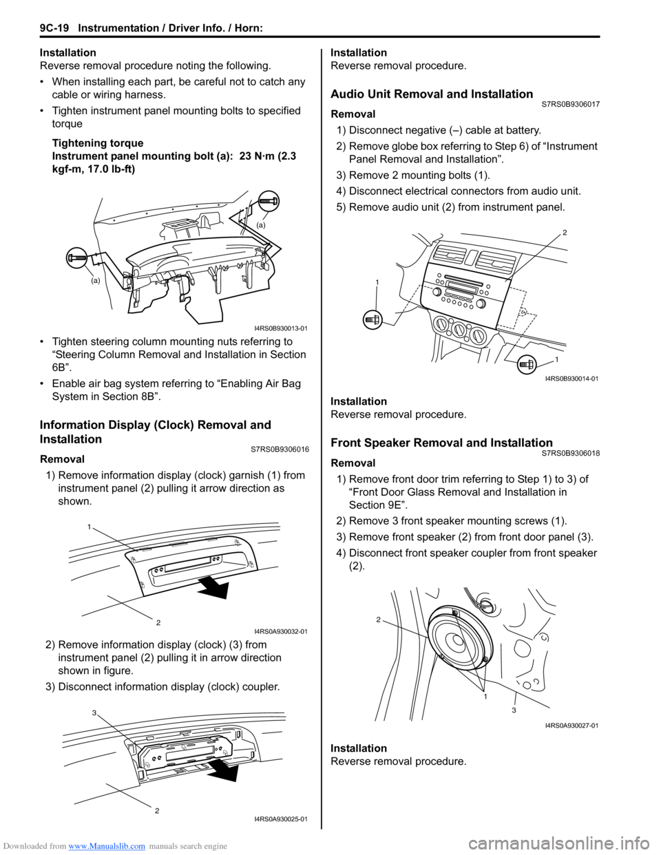
Reverse removal procedure noting the following.
• When installing each part, be careful not to catch any
cable or wiring harness.
• Tighten instrument panel mounting bolts to specified
torque
Tightening torque
Instrument panel mounting bolt (a): 23 N·m (2.3
kgf-m, 17.0 lb-ft)
• Tighten steering column mounting nuts referring to “Steering Column Removal an d Installation in Section
6B”.
• Enable air bag system referring to “Enabling Air Bag System in Section 8B”.
Information Display (Clock) Removal and
Installation
S7RS0B9306016
Removal
1) Remove information display (clock) garnish (1) from instrument panel (2) pulling it arrow direction as
shown.
2) Remove information di splay (clock) (3) from
instrument panel (2) pulli ng it in arrow direction
shown in figure.
3) Disconnect information display (clock) coupler. Installation
Reverse removal procedure.
Audio Unit Removal and InstallationS7RS0B9306017
Removal
1) Disconnect negative (–) cable at battery.
2) Remove globe box referring to Step 6) of “Instrument Panel Removal and Installation”.
3) Remove 2 mounting bolts (1).
4) Disconnect electrical connectors from audio unit.
5) Remove audio unit (2) from instrument panel.
Installation
Reverse removal procedure.
Front Speaker Removal and InstallationS7RS0B9306018
Removal 1) Remove front door trim refe rring to Step 1) to 3) of
“Front Door Glass Remo val and Installation in
Section 9E”.
2) Remove 3 front speaker mounting screws (1).
3) Remove front speaker (2) from front door panel (3).
4) Disconnect front speaker coupler from front speaker (2).
Installation
Reverse removal procedure.
(a) (a)
I4RS0B930013-01
1
2I4RS0A930032-01
3
2I4RS0A930025-01
2
1
1
I4RS0B930014-01
1
2
3
I4RS0A930027-01
Page 1410 of 1496
Downloaded from www.Manualslib.com manuals search engine 10B-7 Body Electrical Control System:
Connector Layout Diagram of BCM and Junction Block AssemblyS7RS0BA202002
BCM and junction block assembly connectors (viewed from harness side)
I4RS0AA20004-01
[A]: Junction block assembly (viewed from BCM side)2. Junction block assembly5. Rear wiper relay
[B]: Junction block assembly (viewed from relay side) 3.Heater relay 6. Rear end door window defogger relay
1. BCM 4. Horn relay7. Turn signal and hazard warning relay