2007 SUZUKI SWIFT Connectors
[x] Cancel search: ConnectorsPage 746 of 1496
Downloaded from www.Manualslib.com manuals search engine 5A-102 Automatic Transmission/Transaxle:
Operation Check
Check pressure control solenoid valves (Pressure
control solenoid and TCC pressure control solenoid)
operation in the either manner of the following.
Using regulated DC power supply
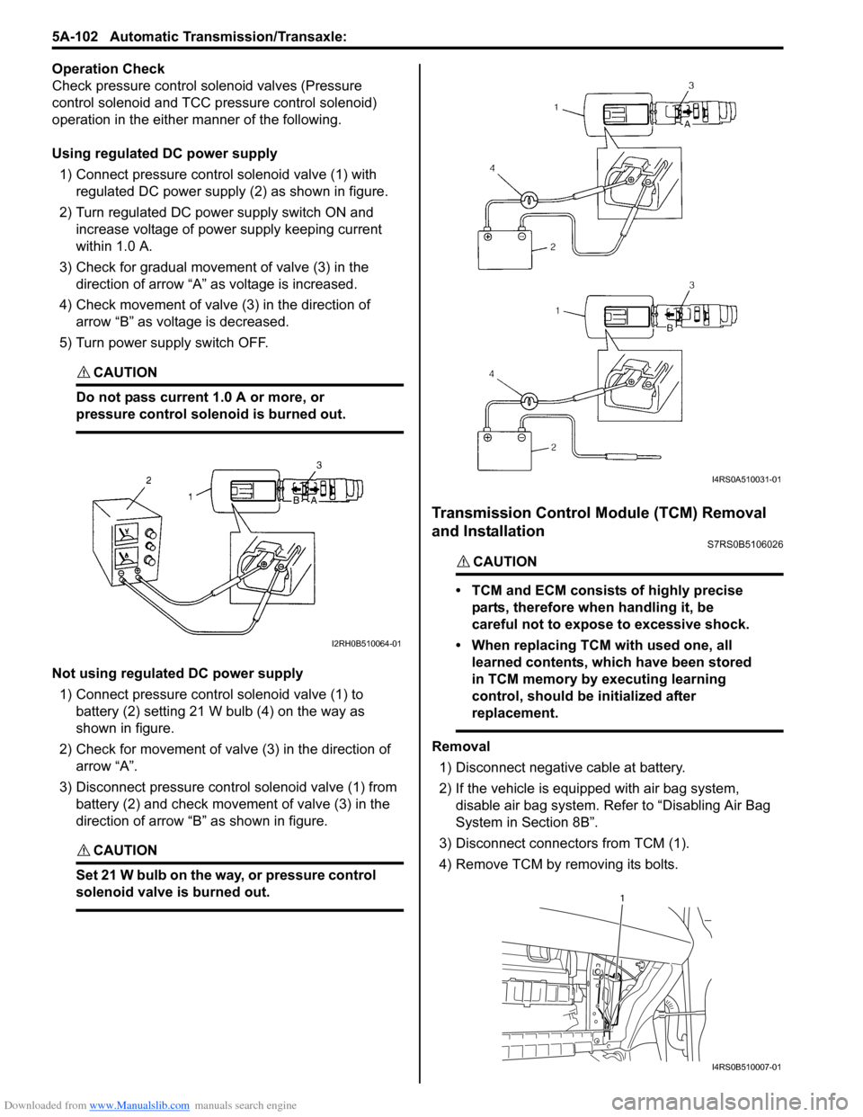
1) Connect pressure contro l solenoid valve (1) with
regulated DC power supply (2) as shown in figure.
2) Turn regulated DC power supply switch ON and increase voltage of power supply keeping current
within 1.0 A.
3) Check for gradual movement of valve (3) in the direction of arrow “A” as voltage is increased.
4) Check movement of valve (3) in the direction of arrow “B” as voltage is decreased.
5) Turn power supply switch OFF.
CAUTION!
Do not pass current 1.0 A or more, or
pressure control solenoid is burned out.
Not using regulated DC power supply 1) Connect pressure control solenoid valve (1) to battery (2) setting 21 W bulb (4) on the way as
shown in figure.
2) Check for movement of valve (3) in the direction of arrow “A”.
3) Disconnect pressure control solenoid valve (1) from battery (2) and check movement of valve (3) in the
direction of arrow “B” as shown in figure.
CAUTION!
Set 21 W bulb on the way, or pressure control
solenoid valve is burned out.
Transmission Control Module (TCM) Removal
and Installation
S7RS0B5106026
CAUTION!
• TCM and ECM consists of highly precise
parts, therefore when handling it, be
careful not to expose to excessive shock.
• When replacing TCM with used one, all learned contents, which have been stored
in TCM memory by executing learning
control, should be initialized after
replacement.
Removal
1) Disconnect negative cable at battery.
2) If the vehicle is equipped with air bag system, disable air bag system. Refer to “Disabling Air Bag
System in Section 8B”.
3) Disconnect connectors from TCM (1).
4) Remove TCM by removing its bolts.
I2RH0B510064-01
I4RS0A510031-01
1
I4RS0B510007-01
Page 747 of 1496
Downloaded from www.Manualslib.com manuals search engine Automatic Transmission/Transaxle: 5A-103
Installation
Reverse removal procedure noting the following.
• Connect TCM connectors securely.
• If the vehicle is equipped with air bag system, be sure to enable air bag system after TCM is back in place.
Refer to “Enabling Air Bag System in Section 8B”.
A/T Relay InspectionS7RS0B5106027
1) Disconnect negative cable at battery.
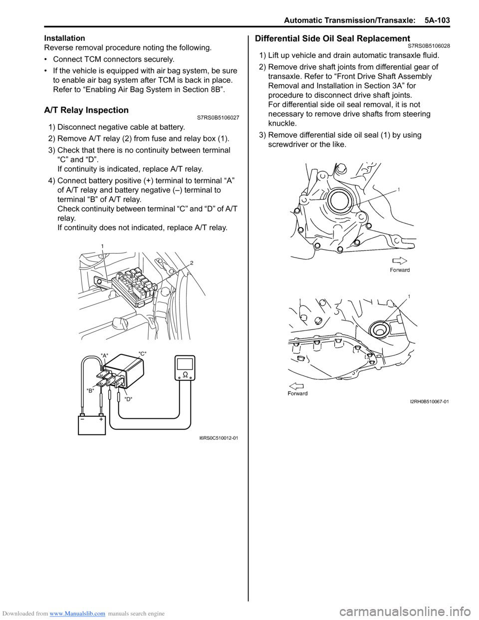
2) Remove A/T relay (2) from fuse and relay box (1).
3) Check that there is no continuity between terminal “C” and “D”.
If continuity is indicated, replace A/T relay.
4) Connect battery positive (+ ) terminal to terminal “A”
of A/T relay and battery negative (–) terminal to
terminal “B” of A/T relay.
Check continuity between terminal “C” and “D” of A/T
relay.
If continuity does not indicated, replace A/T relay.
Differential Side Oil Seal ReplacementS7RS0B5106028
1) Lift up vehicle and drain automatic transaxle fluid.
2) Remove drive shaft joints from differential gear of transaxle. Refer to “Front Drive Shaft Assembly
Removal and Installation in Section 3A” for
procedure to disconnect drive shaft joints.
For differential side oil seal removal, it is not
necessary to remove drive shafts from steering
knuckle.
3) Remove differential side oil seal (1) by using screwdriver or the like.
"D"
"B" "A"
"C"
1
2
I6RS0C510012-01
I2RH0B510067-01
Page 755 of 1496
Downloaded from www.Manualslib.com manuals search engine Automatic Transmission/Transaxle: 5A-111
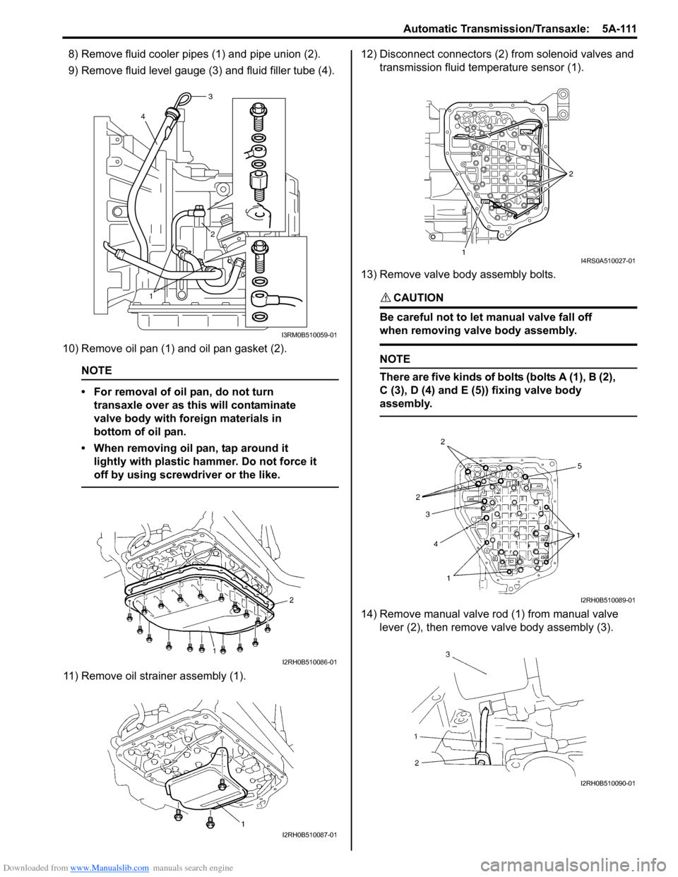
8) Remove fluid cooler pipes (1) and pipe union (2).
9) Remove fluid level gauge (3) and fluid filler tube (4).
10) Remove oil pan (1) and oil pan gasket (2).
NOTE
• For removal of oil pan, do not turn transaxle over as this will contaminate
valve body with foreign materials in
bottom of oil pan.
• When removing oil pan, tap around it lightly with plastic ha mmer. Do not force it
off by using screwdriver or the like.
11) Remove oil strain er assembly (1). 12) Disconnect connectors (2) from solenoid valves and
transmission fluid temperature sensor (1).
13) Remove valve body assembly bolts.
CAUTION!
Be careful not to let manual valve fall off
when removing valve body assembly.
NOTE
There are five kinds of bolts (bolts A (1), B (2),
C (3), D (4) and E (5)) fixing valve body
assembly.
14) Remove manual valve rod (1) from manual valve lever (2), then remove valve body assembly (3).
1 2
4
3
I3RM0B510059-01
I2RH0B510086-01
I2RH0B510087-01
1 2I4RS0A510027-01
I2RH0B510089-01
I2RH0B510090-01
Page 808 of 1496
Downloaded from www.Manualslib.com manuals search engine 5A-164 Automatic Transmission/Transaxle:
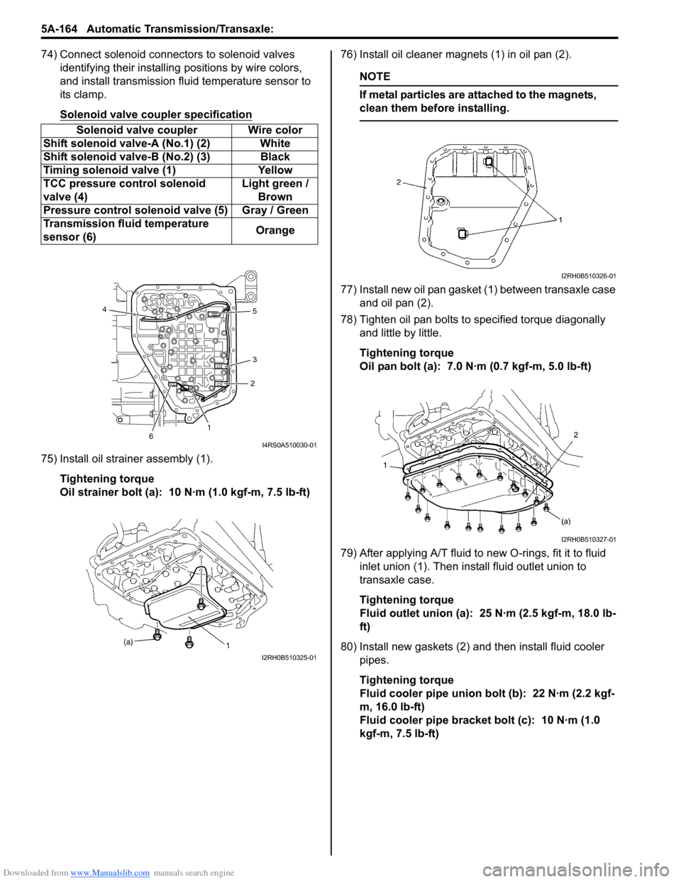
74) Connect solenoid connectors to solenoid valves identifying their installing positions by wire colors,
and install transmission fluid temperature sensor to
its clamp.
Solenoid valve coupler specification
75) Install oil strainer assembly (1).
Tightening torque
Oil strainer bolt (a): 10 N·m (1.0 kgf-m, 7.5 lb-ft) 76) Install oil cleaner magnets (1) in oil pan (2).
NOTE
If metal particles are attached to the magnets,
clean them before installing.
77) Install new oil pan gasket (1) between transaxle case
and oil pan (2).
78) Tighten oil pan bolts to specified torque diagonally and little by little.
Tightening torque
Oil pan bolt (a): 7.0 N·m (0.7 kgf-m, 5.0 lb-ft)
79) After applying A/T fluid to new O-rings, fit it to fluid inlet union (1). Then inst all fluid outlet union to
transaxle case.
Tightening torque
Fluid outlet union (a): 25 N·m (2.5 kgf-m, 18.0 lb-
ft)
80) Install new gaskets (2) and then install fluid cooler pipes.
Tightening torque
Fluid cooler pipe union bolt (b): 22 N·m (2.2 kgf-
m, 16.0 lb-ft)
Fluid cooler pipe bracket bolt (c): 10 N·m (1.0
kgf-m, 7.5 lb-ft)
Solenoid valve coupler Wire color
Shift solenoid valve-A (No.1) (2) White
Shift solenoid val ve-B (No.2) (3) Black
Timing solenoid valve (1) Yellow
TCC pressure control solenoid
valve (4) Light green /
Brown
Pressure control solenoid valve (5) Gray / Green
Transmission fluid temperature
sensor (6) Orange
12
3 5
4
6
I4RS0A510030-01
I2RH0B510325-01
I2RH0B510326-01
I2RH0B510327-01
Page 894 of 1496

Downloaded from www.Manualslib.com manuals search engine 6C-12 Power Assisted Steering System:
Scan Tool Data Definitions
Battery Voltage
This parameter indicates battery positive voltage.
TQS Power Supply (Torque Sensor Power Supply, V)
This parameter indicates the power supply voltage which
the P/S control module supplies to the torque sensor.
TQS Main Torque (Torque Sensor Main Torque, N ⋅m)
The torque sensor is installed to detect the steering force
and the steering directio n. It consists of two
potentiometers and the main torque sensor is one of
these.
TQS Sub Torque (Torque Sensor Sub Torque, N ⋅m)
The torque sensor is installed to detect the steering force
and the steering directio n. It consists of two
potentiometers and the sub-torque sensor is one of
these. Its output characteristics are compared with those
of the main torque sensor.
Assist Torque (N ⋅m)
This parameter is an internal parameter of the P/S
control module. It is obtained by computing the torque
sensor input signal. Motor Control (Motor Control Current, A)
Based on the input signal, the P/S control module
determines the assist amount
and controls the current to
the motor suitable for that a ssist amount. This parameter
indicates that control value.
Motor Monitor (Motor Monitor Current, A)
This parameter indicates the actually measured value of
the current flowing to the motor. The motor circuit
condition is diagnosed by co mparing this parameter with
“Motor Control” parameter described previously.
Vehicle Speed (km/h, MPH)
Vehicle speed signal is fed from BCM. P/S control
module determines the amount of power assist based on
this vehicle speed signal and the torque sensor signal.
Engine Speed (rpm)
Engine speed signal is fed from the ECM so that it can
be used for trouble diagnos is of the electric power
steering system.
Motor Volt (V)
This parameter indicates the voltage between motor
terminals.
Ignition switch (ON, OFF)
This parameter indicates the condition of the power
supply through the ignition switch.
Visual InspectionS7RS0B6304007
Visually check the following pats and system.
P/S System Symptom DiagnosisS7RS0B6304008
This section describes trouble diagnosis of the P/S system parts whose trouble is not indicated by the on-board
diagnostic system (self-diagnostic functi on). When no malfunction is indicated by the on-board diagnostic system
(self-diagnosis function) and those stee ring basic parts as described in “Steering Symptom Diagnosis in Section 6A”
are all in good condition, check the following power steer ing system parts which may be a possible cause for each
symptom of the steering. Inspection Item Referring section
Battery Level, leakage, color “Batte ry Description in Section 1J”
Connectors of electric wire
harness Disconnection friction “Intermittent and Poor
Connection Inspection in Section 00”
Fuses Burning “Cautions in Body Electric al System Servicing in Section 9A”
Parts Installation, damage
Other parts that can be checked visually
Condition Possible cause Correction / Reference Item
Steering wheel feels
heavy (Perform “Steering
Force Check” before
diagnosis.) Steering wheel installed improperly
(twisted)
Install steering wheel correctly.
Poor performance of torque sensor Check torque sensor referring to “Torque
Sensor and Its Circuit Inspection”.
Poor performance of P/S motor Check motor referring to “P/S Motor and Its
Circuit Inspection”.
Steering gear case assembly faulty Replace.
Poor performance of vehicle speed
signal from ECM Check vehicle speed signal circuit referring to
“DTC C1121 / C1123 / C1124: VSS Circuit
Failure”.
Page 909 of 1496
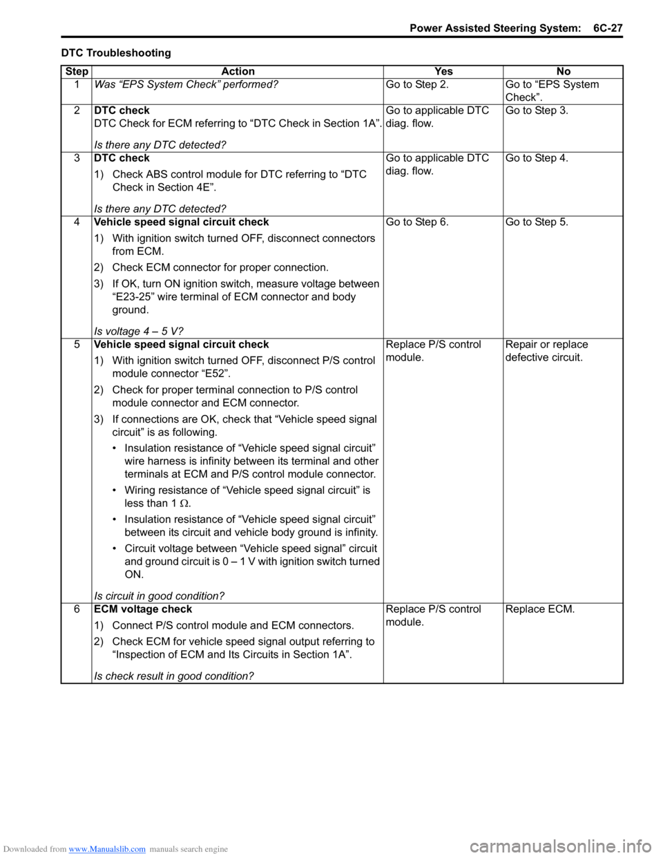
Downloaded from www.Manualslib.com manuals search engine Power Assisted Steering System: 6C-27
DTC TroubleshootingStep Action Yes No 1 Was “EPS System Check” performed? Go to Step 2. Go to “EPS System
Check”.
2 DTC check
DTC Check for ECM referring to “DTC Check in Section 1A”.
Is there any DTC detected? Go to applicable DTC
diag. flow.
Go to Step 3.
3 DTC check
1) Check ABS control module for DTC referring to “DTC
Check in Section 4E”.
Is there any DTC detected? Go to applicable DTC
diag. flow.
Go to Step 4.
4 Vehicle speed signal circuit check
1) With ignition switch turned OFF, disconnect connectors
from ECM.
2) Check ECM connector for proper connection.
3) If OK, turn ON ignition switch, measure voltage between “E23-25” wire terminal of ECM connector and body
ground.
Is voltage 4 – 5 V? Go to Step 6.
Go to Step 5.
5 Vehicle speed signal circuit check
1) With ignition switch turned OFF, disconnect P/S control
module connector “E52”.
2) Check for proper terminal connection to P/S control module connector and ECM connector.
3) If connections are OK, chec k that “Vehicle speed signal
circuit” is as following.
• Insulation resistance of “Vehicle speed signal circuit” wire harness is infinity between its terminal and other
terminals at ECM and P/S control module connector.
• Wiring resistance of “Vehicle speed signal circuit” is less than 1 Ω.
• Insulation resistance of “Vehicle speed signal circuit” between its circuit and vehicle body ground is infinity.
• Circuit voltage between “Vehicle speed signal” circuit and ground circuit is 0 – 1 V with ignition switch turned
ON.
Is circuit in good condition? Replace P/S control
module.
Repair or replace
defective circuit.
6 ECM voltage check
1) Connect P/S control mo dule and ECM connectors.
2) Check ECM for vehicle speed signal output referring to “Inspection of ECM and Its Circuits in Section 1A”.
Is check result in good condition? Replace P/S control
module.
Replace ECM.
Page 911 of 1496
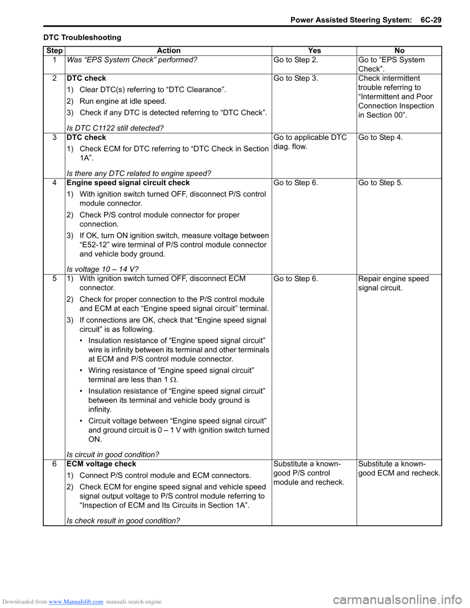
Downloaded from www.Manualslib.com manuals search engine Power Assisted Steering System: 6C-29
DTC TroubleshootingStep Action Yes No 1 Was “EPS System Check” performed? Go to Step 2. Go to “EPS System
Check”.
2 DTC check
1) Clear DTC(s) referring to “DTC Clearance”.
2) Run engine at idle speed.
3) Check if any DTC is detecte d referring to “DTC Check”.
Is DTC C1122 still detected? Go to Step 3. Check intermittent
trouble referring to
“Intermittent and Poor
Connection Inspection
in Section 00”.
3 DTC check
1) Check ECM for DTC referring to “DTC Check in Section
1A”.
Is there any DTC related to engine speed? Go to applicable DTC
diag. flow.
Go to Step 4.
4 Engine speed signal circuit check
1) With ignition switch turned OFF, disconnect P/S control
module connector.
2) Check P/S control module connector for proper connection.
3) If OK, turn ON ignition switch, measure voltage between “E52-12” wire terminal of P/S control module connector
and vehicle body ground.
Is voltage 10 – 14 V? Go to Step 6.
Go to Step 5.
5 1) With ignition switch turned OFF, disconnect ECM connector.
2) Check for proper connection to the P/S control module and ECM at each “Engine speed signal circuit” terminal.
3) If connections are OK, chec k that “Engine speed signal
circuit” is as following.
• Insulation resistance of “Engine speed signal circuit” wire is infinity between its terminal and other terminals
at ECM and P/S control module connector.
• Wiring resistance of “Engine speed signal circuit” terminal are less than 1 Ω.
• Insulation resistance of “Engine speed signal circuit” between its terminal and vehicle body ground is
infinity.
• Circuit voltage between “Engine speed signal circuit” and ground circuit is 0 – 1 V with ignition switch turned
ON.
Is circuit in good condition? Go to Step 6.
Repair engine speed
signal circuit.
6 ECM voltage check
1) Connect P/S control mo dule and ECM connectors.
2) Check ECM for engine speed signal and vehicle speed signal output voltage to P/S control module referring to
“Inspection of ECM and Its Circuits in Section 1A”.
Is check result in good condition? Substitute a known-
good P/S control
module and recheck.
Substitute a known-
good ECM and recheck.
Page 916 of 1496
![SUZUKI SWIFT 2007 2.G Service Workshop Manual Downloaded from www.Manualslib.com manuals search engine 6C-34 Power Assisted Steering System:
P/S Control Module Power Supply and Ground Circuit CheckS7RS0B6304022
Wiring Diagram
1
[A ]
123
4 5 67
8 SUZUKI SWIFT 2007 2.G Service Workshop Manual Downloaded from www.Manualslib.com manuals search engine 6C-34 Power Assisted Steering System:
P/S Control Module Power Supply and Ground Circuit CheckS7RS0B6304022
Wiring Diagram
1
[A ]
123
4 5 67
8](/manual-img/20/7607/w960_7607-915.png)
Downloaded from www.Manualslib.com manuals search engine 6C-34 Power Assisted Steering System:
P/S Control Module Power Supply and Ground Circuit CheckS7RS0B6304022
Wiring Diagram
1
[A ]
123
4 5 67
89
11
10
12 13
141516
17 18 19 20
[B ]
7
1
2
MBLK
REDE51-1
E51-2
12V
LT GRN
/BLKE52-1 E49-1
GRNGRNWHTBLK
WHY
3
3
5
6
1 2
E49-2BLK
I7RS0B630012-01
[A]: Connector “E52” (viewed from harness side)
2. Ignition switch5. “EPS” fuse
[B]: Connector “E49” (viewed from harness side) 3. Individual circuit fuse box No.1 6. “IG1 SIG” fuse
1. Main fuse box 4. Junction block assembly7. P/S control module
StepAction YesNo
1 Circuit fuse check
1) Disconnect P/S control modu le connector with ignition
switch turned OFF.
2) Check for proper connection to P/S control module connector at “E49-1”, “E49-2” and “E52-1” terminals.
3) If OK, check “P/S” fuse and “IG1 SIG” fuse for blowing.
Are “P/S” fuse and “IG1 SIG” fuse in good condition? Go to Step 2.
Replace fuse(s) and
check for short in
circuits connected to
fuse(s).
2 Power supply circuit check
1) Measure voltage between “E49-1” terminal of P/S
control module connector and body ground.
Is voltage 10 - 14 V? Go to Step 3.
“GRN” or “BLK” wire is
open circuit.
3 Ignition signal check
1) Turn ignition switch to ON position.
2) Measure voltage between “E52-1” terminal of P/S
control module connector and body ground.
Is voltage 10 - 14 V? Go to Step 4.
“LT GRN/BLK” or “GRN”
wire is open circuit.
4 P/S control module ground circuit check
1) Turn ignition switch to OFF position.
2) Disconnect connectors from P/S control module.
3) Measure resistance between “E49-2” terminals of P/S
control module connector and body ground.
Is resistance 1
Ω or less? Go to Step 5. “BLK” wire is open or
high resistance circuit.