2007 SUZUKI SWIFT Voltage
[x] Cancel search: VoltagePage 560 of 1496
Downloaded from www.Manualslib.com manuals search engine 4E-21 ABS:
DTC C1057: Power Source CircuitS7RS0B4504014
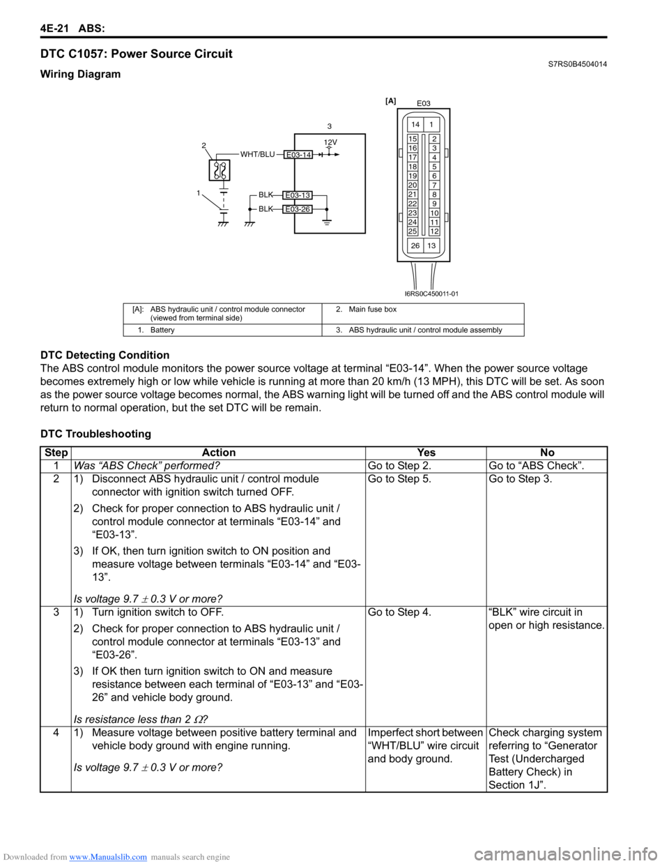
Wiring Diagram
DTC Detecting Condition
The ABS control module monitors the power source voltage at terminal “E03-14”. When the power source voltage
becomes extremely high or low while vehicle is running at more than 20 km/h (13 MPH), this DTC will be set. As soon
as the power source volta ge becomes normal, the ABS warning light will be turned off and the ABS control module will
return to normal operation, bu t the set DTC will be remain.
DTC Troubleshooting
[A]: ABS hydraulic unit / control module connector (viewed from terminal side) 2. Main fuse box
1. Battery 3. ABS hydraulic unit / control module assembly
E03-14WHT/BLU
1 2
3
BLK
BLK
E03-13
E03-26
[A]
E03
15
16
17
18
19
20
21
22
23
24
25 2
3
4
5
6
7
8
9
10
11
12
1
13
14
26
12V
I6RS0C450011-01
Step
Action YesNo
1 Was “ABS Check” performed? Go to Step 2.Go to “ABS Check”.
2 1) Disconnect ABS hydraulic unit / control module connector with ignition switch turned OFF.
2) Check for proper connection to ABS hydraulic unit / control module connector at terminals “E03-14” and
“E03-13”.
3) If OK, then turn ignition switch to ON position and measure voltage between terminals “E03-14” and “E03-
13”.
Is voltage 9.7
± 0.3 V or more? Go to Step 5. Go to Step 3.
3 1) Turn ignition switch to OFF. 2) Check for proper connection to ABS hydraulic unit / control module connector at terminals “E03-13” and
“E03-26”.
3) If OK then turn ignition switch to ON and measure resistance between each terminal of “E03-13” and “E03-
26” and vehicle body ground.
Is resistance less than 2
Ω? Go to Step 4. “BLK” wire circuit in
open or high resistance.
4 1) Measure voltage between positive battery terminal and vehicle body ground with engine running.
Is voltage 9.7
± 0.3 V or more? Imperfect short between
“WHT/BLU” wire circuit
and body ground.
Check charging system
referring to “Generator
Test (Undercharged
Battery Check) in
Section 1J”.
Page 561 of 1496

Downloaded from www.Manualslib.com manuals search engine ABS: 4E-22
DTC C1061: ABS Pump Motor and/or Motor Driver CircuitS7RS0B4504015
Wiring Diagram
DTC Detecting Condition
The ABS control module monitors the voltage at monitor terminal of pump motor circuit constantly with the ignition
switch turned ON. It sets this DTC when the voltage at the monitor terminal does not become high / low according to
ON/OFF commands to the motor driver (transistor) of the module (does not follow these commands).
DTC Troubleshooting 5 1) Measure voltage between terminals “E03-14” and “E03-
13” with engine running.
Is voltage 18
± 1.0 V or less? Poor connection of
“E03-14” and/or “E03-
13” terminals. If the
terminals are in good
condition, substitute a
known-good ABS
hydraulic unit / control
module and recheck.Check charging system
referring to “Generator
Test (Overcharged
Battery Check) in
Section 1J”.
Step Action Yes No
WHT/RED
1 2
5
BLK
BLK
E03-13
E03-26
[A]
E03
15
16
17
18
19
20
21
22
23
24
25 2
3
4
5
6
7
8
9
10
11
12
1
13
14
26
M
3
4E03-1
12V
12V
I6RS0C450012-01
[A]: ABS hydraulic unit / control module connector (viewed from terminal side) 2. Main fuse box 4. ABS pump motor
1. Battery 3. Pump motor driver (transistor) 5. ABS hydraulic unit / control module assembly
StepAction YesNo
1 Was “ABS Check” performed? Go to Step 2.Go to “ABS Check”.
2 1) Turn Ignition switch to OFF position.
2) Disconnect ABS hydraulic unit / control module connector.
3) Check for proper connection to ABS hydraulic unit / control module connector at terminal “E03-1”.
4) If OK, then measure voltage between terminal “E03-1” of module connector and body ground.
Is it 10 – 14 V? Go to Step 3.
“WHT/RED” circuit
open.
3 Measure resistance between terminal “E03-13” and “E03- 26” of ABS hydraulic unit / co ntrol module connector and
body ground.
Is resistance less than 1
Ω? Substitute a known-
good ABS hydraulic unit
/ control module
assembly and recheck.
Ground circuit for ABS
hydraulic unit / control
module open or high
resistance.
Page 562 of 1496
Downloaded from www.Manualslib.com manuals search engine 4E-23 ABS:
DTC C1063: Solenoid Valve Power Supply Driver CircuitS7RS0B4504016
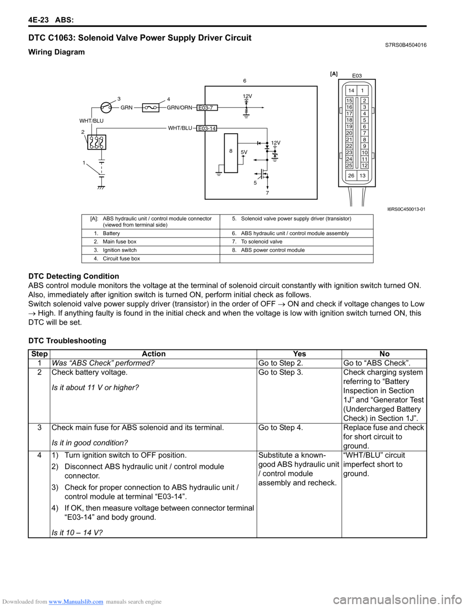
Wiring Diagram
DTC Detecting Condition
ABS control module monitors the voltage at the terminal of solenoid circuit constantly with ignition switch turned ON.
Also, immediately after ignition switch is turned ON, perform initial check as follows.
Switch solenoid valve power supply driv er (transistor) in the order of OFF → ON and check if voltage changes to Low
→ High. If anything faulty is found in the initial check and when the voltage is low with ignition switch turned ON, this
DTC will be set.
DTC Troubleshooting
[A] E03
15
16
17
18
19
20
21
22
23
24
25 2
3
4
5
6
7
8
9
10
11
12
1
13
14
266
WHT/BLU
12V
5E03-14
5V
12V
8
GRN/ORNE03-7
WHT/BLU
GRN
1
2 3
4
7
I6RS0C450013-01
[A]: ABS hydraulic unit / control module connector
(viewed from terminal side) 5. Solenoid valve power supp
ly driver (transistor)
1. Battery 6. ABS hydraulic unit / control module assembly
2. Main fuse box 7. To solenoid valve
3. Ignition switch 8. ABS power control module
4. Circuit fuse box
Step Action YesNo
1 Was “ABS Check” performed? Go to Step 2.Go to “ABS Check”.
2 Check battery voltage.
Is it about 11 V or higher? Go to Step 3.
Check charging system
referring to “Battery
Inspection in Section
1J” and “Generator Test
(Undercharged Battery
Check) in Section 1J”.
3 Check main fuse for ABS solenoid and its terminal.
Is it in good condition? Go to Step 4.
Replace fuse and check
for short circuit to
ground.
4 1) Turn ignition switch to OFF position.
2) Disconnect ABS hydraulic unit / control module connector.
3) Check for proper connection to ABS hydraulic unit / control module at terminal “E03-14”.
4) If OK, then measure voltage between connector terminal “E03-14” and body ground.
Is it 10 – 14 V? Substitute a known-
good ABS hydraulic unit
/ control module
assembly and recheck.
“WHT/BLU” circuit
imperfect short to
ground.
Page 563 of 1496

Downloaded from www.Manualslib.com manuals search engine ABS: 4E-24
DTC C1071: ABS Control ModuleS7RS0B4504017
Wiring Diagram
DTC Detecting Condition
This DTC will be set when an internal malfunction is detected in the ABS control module.
DTC Troubleshooting
1
2
WHT/RED
12VM
3
4
E03-1
E03-14
BLK
BLK
E03-13
E03-26
WHT/BLU [A]
E03
15
16
17
18
19
20
21
22
23
24
25 2
3
4
5
6
7
8
9
10
11
12
1
13
14
26
I6RS0C450014-01
[A]: ABS hydraulic unit / control module connector
(viewed from terminal side) 2. Main fuse box 4. ABS hydraulic unit / control module assembly
1. Battery 3. ABS power control module
Step Action YesNo
1 Was “ABS Check” performed? Go to Step 2.Go to “ABS Check”.
2 Clear all DTCs and check DTC.
Is it DTC C1071? Go to Step 3.
Could be a temporary
malfunction of the ABS
control module.
3 1) Check for proper connection of ABS hydraulic unit / control module connector.
2) If OK, disconnect ABS hydr aulic unit / control module
connector and check the following.
• Voltage “E03-1” terminal: 10 – 14 V
• Voltage “E03-14” terminal: 10 – 14 V
• Resistance between “E03-13” and body ground: Continuity
• Resistance between “E03-26” and body ground: Continuity
Are the check result as specified? Replace ABS hydraulic
unit / control module
assembly.
Repair “WHT/RED”,
“WHT/BLU” and/or
“BLK” circuit and
recheck.
Page 567 of 1496
Downloaded from www.Manualslib.com manuals search engine ABS: 4E-28
Repair Instructions
ABS Hydraulic Unit Operation CheckS7RS0B4506001
1) Check that basic brake system other than ABS is in good condition.
2) Check that battery voltage is 11 V or higher.
3) Lift up vehicle.
4) Set transmission to neutral and release parking brake.
5) Turn each wheel gradually by hand to check if brake dragging occurs. If it does, correct.
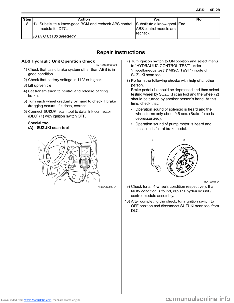
6) Connect SUZUKI scan tool to data link connector (DLC) (1) with ignition switch OFF.
Special tool
(A): SUZUKI scan tool 7) Turn ignition switch to ON position and select menu
to “HYDRAULIC CONTROL TEST” under
“miscellaneous test” (“MISC. TEST”) mode of
SUZUKI scan tool.
8) Perform the following checks with help of another person.
Brake pedal (1) should be depressed and then select
testing wheel by SUZUKI scan tool and the wheel (2)
should be turned by another person’s hand. At this
time, check that:
• Operation sound of solenoid is heard and the wheel turns only about 0.5 sec. (Brake force is
depressurized).
• Operation sound of pump motor is heard and pulsation is felt at brake pedal.
9) Check for all 4-wheels co ndition respectively. If a
faulty condition is found, replace hydraulic unit /
control module assembly.
10) After completing the check, turn ignition switch to OFF position and disconnect SUZUKI scan tool from
DLC.
8 1) Substitute a know-good BCM and recheck ABS control
module for DTC.
IS DTC U1100 detected? Substitute a know-good
ABS control module and
recheck.
End.
Step Action Yes No
1 (A)I4RS0A450020-01
I4RH01450021-01
Page 570 of 1496
Downloaded from www.Manualslib.com manuals search engine 4E-31 ABS:
2) Bleed air from brake system referring to “Air Bleeding of Brake System in Section 4A”.
3) Check each installed part for fluid leakage and perform “ABS Hydraulic Un it Operation Check”.
NOTE
For new ABS hydraulic unit / control module
assembly, if “ABS Hydraulic Unit Operation
Check” has not been performed, ABS
warning light may flash when ignition switch
is turned ON position.
Accordingly preform “ABS Hydraulic Unit
Operation Check” to stop flashing of ABS
warning light.
Front / Rear Wheel Speed Sensor On-Vehicle
Inspection
S7RS0B4506005
Output Voltage Inspection
1) Disconnect negative cable from battery.
2) Hoist vehicle a little.
3) Disconnect wheel speed sensor connector.
4) Disconnect wheel speed grommet from vehicle body.
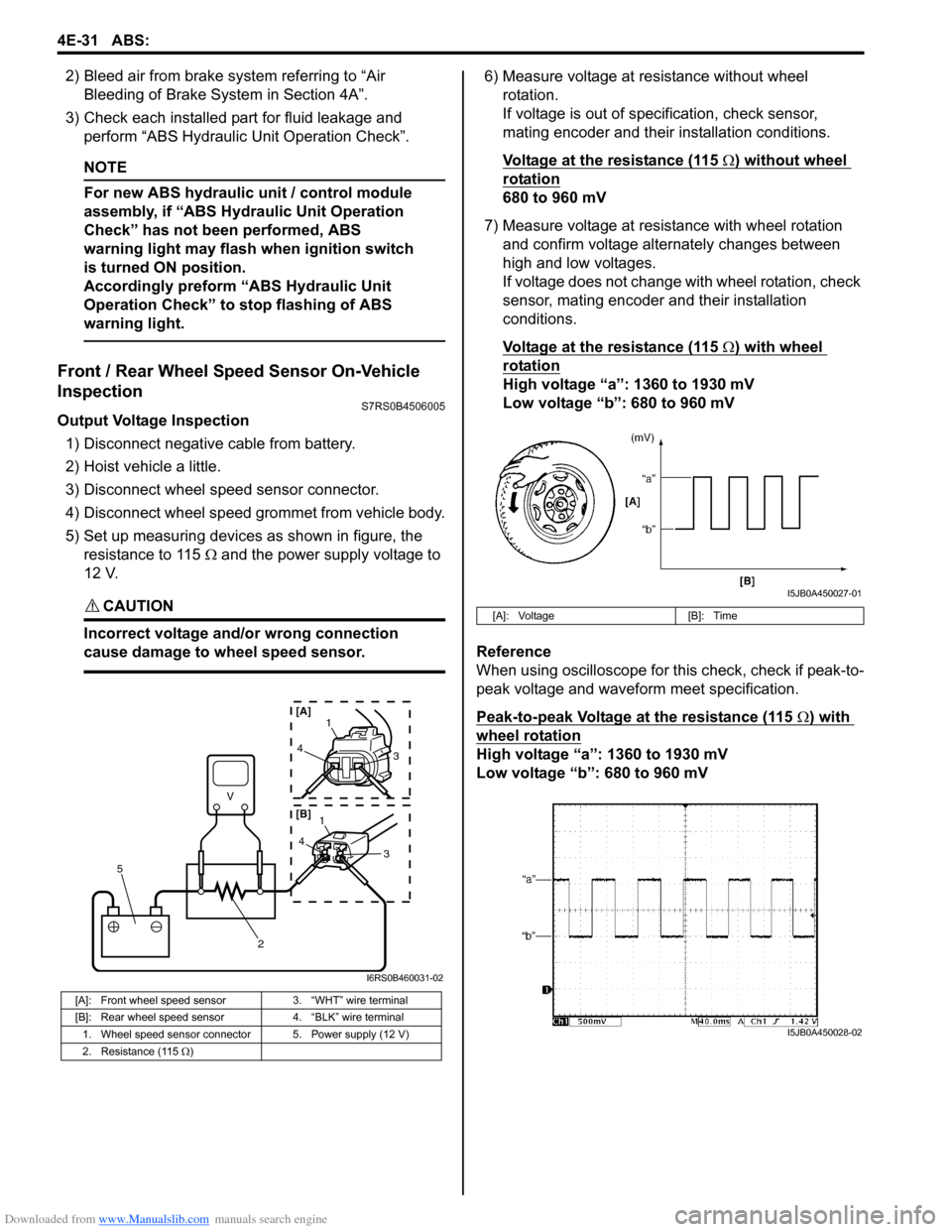
5) Set up measuring devices as shown in figure, the resistance to 115 Ω and the power supply voltage to
12 V.
CAUTION!
Incorrect voltage and/or wrong connection
cause damage to wheel speed sensor.
6) Measure voltage at resistance without wheel rotation.
If voltage is out of specification, check sensor,
mating encoder and their installation conditions.
Voltage at the resistance (115
Ω) without wheel
rotation
680 to 960 mV
7) Measure voltage at resistance with wheel rotation and confirm voltage alternately changes between
high and low voltages.
If voltage does not change with wheel rotation, check
sensor, mating encoder and their installation
conditions.
Voltage at the resistance (115
Ω) with wheel
rotation
High voltage “a”: 1360 to 1930 mV
Low voltage “b”: 680 to 960 mV
Reference
When using oscilloscope for this check, check if peak-to-
peak voltage and waveform meet specification.
Peak-to-peak Voltage at the resistance (115
Ω) with
wheel rotation
High voltage “a”: 1360 to 1930 mV
Low voltage “b”: 680 to 960 mV
[A]: Front wheel speed sensor 3. “WHT” wire terminal
[B]: Rear wheel speed sensor 4. “BLK” wire terminal
1. Wheel speed sensor connector 5. Power supply (12 V)
2. Resistance (115 Ω )
V
2
5
41
3
43
1
[A]
[B]
I6RS0B460031-02
[A]: Voltage [B]: Time
I5JB0A450027-01
I5JB0A450028-02
Page 579 of 1496
Downloaded from www.Manualslib.com manuals search engine Electronic Stability Program: 4F-5
Yaw rate / G sensor
The yaw rate / G sensor consists of the yaw rate (angular velocity in the vehicle turning direction) sensor and right-left
G (acceleration in right-left direction) sensor and is mounted to the P/S controller B/K at the lower part of the center
console. It detects the angular velocity in the vehicle turn ing direction and movement in the right-left direction, and
then it sends that information to ESP ® control module.
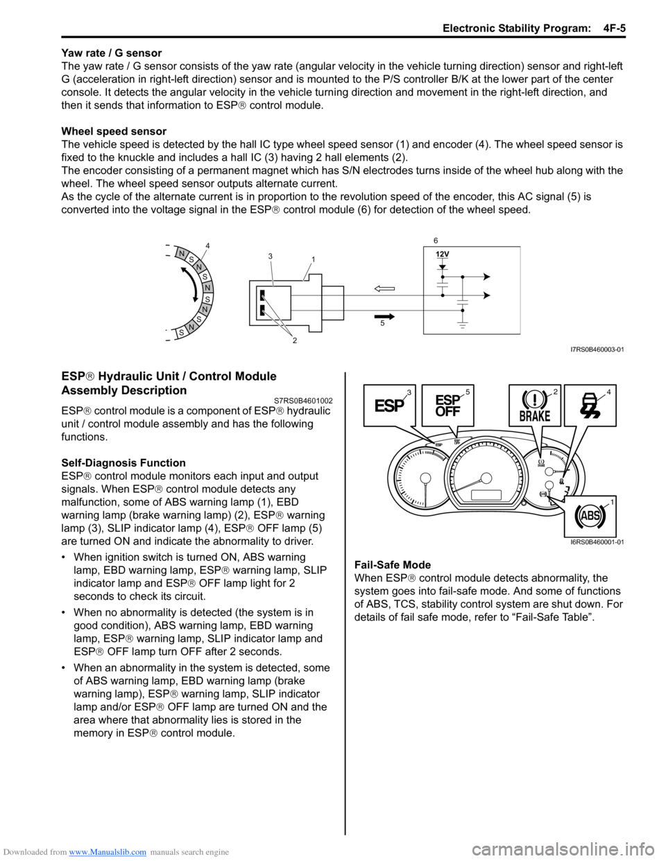
Wheel speed sensor
The vehicle speed is detected by the hall IC type wheel speed sensor (1) and encoder (4). The wheel speed sensor is
fixed to the knuckle and includes a hall IC (3) having 2 hall elements (2).
The encoder consisting of a permanent ma gnet which has S/N electrodes turns inside of the wheel hub along with the
wheel. The wheel speed sensor outputs alternate current.
As the cycle of the alternate current is in proportion to the revolution speed of the encoder, this AC signal (5) is
converted into the voltage signal in the ESP ® control module (6) for detection of the wheel speed.
ESP ® Hydraulic Unit / Control Module
Assembly Description
S7RS0B4601002
ESP ® control module is a component of ESP ® hydraulic
unit / control module assembly and has the following
functions.
Self-Diagnosis Function
ESP ® control module monitors each input and output
signals. When ESP ® control module detects any
malfunction, some of ABS warning lamp (1), EBD
warning lamp (brake warning lamp) (2), ESP ® warning
lamp (3), SLIP indicator lamp (4), ESP ® OFF lamp (5)
are turned ON and indicate the abnormality to driver.
• When ignition switch is turned ON, ABS warning lamp, EBD warning lamp, ESP ® warning lamp, SLIP
indicator lamp and ESP ® OFF lamp light for 2
seconds to check its circuit.
• When no abnormality is detected (the system is in good condition), ABS warning lamp, EBD warning
lamp, ESP ® warning lamp, SLIP indicator lamp and
ESP ® OFF lamp turn OFF after 2 seconds.
• When an abnormality in the system is detected, some of ABS warning lamp, EBD warning lamp (brake
warning lamp), ESP ® warning lamp, SLIP indicator
lamp and/or ESP ® OFF lamp are turned ON and the
area where that abnormality lies is stored in the
memory in ESP ® control module. Fail-Safe Mode
When ESP
® control module detects abnormality, the
system goes into fail-safe mode. And some of functions
of ABS, TCS, stability control system are shut down. For
details of fail safe mode, re fer to “Fail-Safe Table”.
S
N
S
N
S
N
N
S
N
S
12V
2
3
1
5
4
6I7RS0B460003-01
3245
1
I6RS0B460001-01
Page 582 of 1496
Downloaded from www.Manualslib.com manuals search engine 4F-8 Electronic Stability Program:
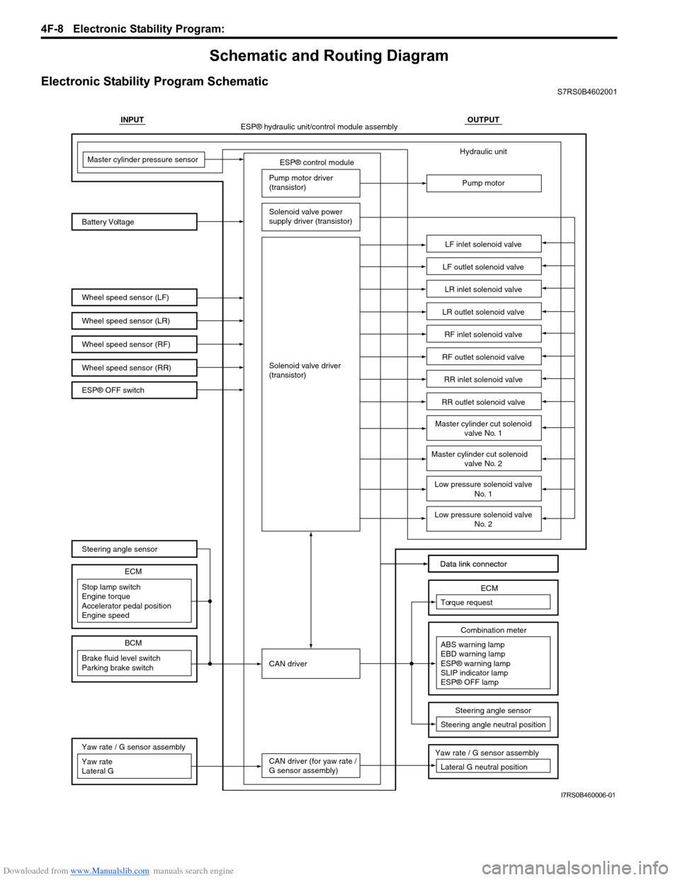
Schematic and Routing Diagram
Electronic Stability Program SchematicS7RS0B4602001
INPUTOUTPUT
ESP® control module
Wheel speed sensor (LF)
Wheel speed sensor (LR)
Wheel speed sensor (RF) Battery VoltageMaster cylinder pressure sensor
Pump motor driver
(transistor)
Solenoid valve power
supply driver (transistor)
Solenoid valve driver
(transistor)
CAN driver
CAN driver (for yaw rate /
G sensor assembly) Hydraulic unit
Pump motor
LF inlet solenoid valve
LF outlet solenoid valve
LR inlet solenoid valve
LR outlet solenoid valve
RF inlet solenoid valve
RF outlet solenoid valve
RR inlet solenoid valve
RR outlet solenoid valve
Data link connector
Data link connector
ESP® hydraulic unit/control module assembly
Wheel speed sensor (RR)
Master cylinder cut solenoid valve No. 1
Master cylinder cut solenoid
valve No. 2
Low pressure solenoid valve No. 1
Low pressure solenoid valveNo. 2
Stop lamp switch
Engine torque
Accelerator pedal position
Engine speed ECM
Brake fluid level switch
Parking brake switch
BCM
Steering angle sensor
ESP® OFF switch
Yaw rate
Lateral G Yaw rate / G sensor assembly
ABS warning lamp
EBD warning lamp
ESP® warning lamp
SLIP indicator lamp
ESP® OFF lampCombination meter
Torque request
ECM
Steering angle neutral positionSteering angle sensor
Yaw rate / G sensor assembly
Lateral G neutral position
I7RS0B460006-01