Page 455 of 1496
Downloaded from www.Manualslib.com manuals search engine Rear Suspension: 2C-1
Suspension
Rear Suspension
General Description
Rear Suspension ConstructionS7RS0B2301001
I6RS0C230001-03
A: View A7. Circlip 14. Spindle cap : 90 N⋅m (9.0 kgf-m, 65.0 lb-ft)
1. Rear coil spring 8. Rear trailing arm bolt 15. Wheel hub : 85 N⋅m (8.5 kgf-m, 61.5 lb-ft)
2. Rear spring upper seat 9. Rear shock absorber upper
nut 16. Washer
: 175 N⋅m (17.5 kgf-m, 126.5 lb-ft)
3. Rear shock absorber 10. Rear shock absorber lower nut “F”: Vehicle front : 88 N⋅m (8.8 kgf-m, 64.0 lb-ft)
4. Rear axle 11. Rear spindle bolt “I”: Body inside : Do not reuse.
5. Wheel bearing : Seal side of bearing comes
brake back plate side. 12. Wheel nut
: 73 N⋅m (7.3 kgf-m, 53.0 lb-ft)
6. Brake disc 13. Rear spindle nut
: Caulk spindle nut as shown
“a”. :28 N
⋅m (2.8 kgf-m, 20.0 lb-ft)
Page 456 of 1496

Downloaded from www.Manualslib.com manuals search engine 2C-2 Rear Suspension:
Repair Instructions
Rear Wheel Alignment InspectionS7RS0B2306017
Measure toe and camber referring to “Front Wheel
Alignment Inspection and Adjustment in Section 2B”.
NOTE
Rear suspension is not adjustable structure.
Rear toe (total)
: IN 3.8 ± 3.8 mm (IN 0.1969 ± 0.1969 in)
Rear camber
: –1 ° ± 1
If measured value is out of specified value, check
following items for damage, deformation and crack.
• Rear axle (torsion beam)
• Spindle, wheel hub or wheel bearing
• Vehicle body
Rear Shock Absorber Removal and InstallationS7RS0B2306001
Removal 1) Hoist vehicle and remove rear wheels.
2) Remove tail end member trim (1) and quarter inner trim (2).
3) Support rear axle by using floor jack to prevent it from lowering.
4) Remove shock absorber lower nut.
5) Remove shock absorber upper nut. Then remove shock absorber, a pair of upper washers and lower
washer. Installation
1) Install shock absorber (1), a pair of upper washers (2) and lower washer.
Tighten new rear shock absorber upper nut (4) and
lower nut temporarily at this step.
CAUTION!
Never reuse the removed rear shock
absorber upper nut.
NOTE
A pair of upper washers (2) are installed as
shown in figure.
3. Clip
3
3 2
3
1
3
I7RS0B230001-01
3. Body panel
14
3 2
I6RS0C230005-01
Page 459 of 1496
Downloaded from www.Manualslib.com manuals search engine Rear Suspension: 2C-5
Installation1) Install coil spring (1) on spring seat (2) of rear axle and mate spring open end with stepped part (3) of
spring lower seat and raise rear axle.
2) Install shock absorbers (1) lower side (right & left) to rear axle.
Install washers and tighten shock absorber lower
nuts (2) temporarily by hand at this step. 3) Remove floor jacks from rear axle.
4) Install wheels and tighten wheel nuts to specified
torque.
Tightening torque
Wheel nut: 85 N·m (8.5 kgf-m, 61.5 lb-ft)
5) Lower hoist and vehicle in unloaded condition, tighten shock absorber lower nuts (a) to specified
torque.
Tightening torque
Rear shock absorber lower nut (a): 90 N·m (9.0
kgf-m, 65.0 lb-ft)
Spring Upper Seat / Spring Lower Seat
Inspection
S7RS0B2306006
Inspect for cracks, deformation or damage.
Replace any defective part.
F: Vehicle front
I4RS0A230011-01
1
2
I4RS0A230012-01
(a)
I4RS0A230013-01
I4RS0A230015-01
Page 461 of 1496

Downloaded from www.Manualslib.com manuals search engine Rear Suspension: 2C-7
3) Remove rear brake caliper assemblies (right & left)
and brake discs (right & left ). For details, refer to
Step 2) to 3) of “Removal” under “Rear Brake Disc
Removal and Installa tion in Section 4C”.
4) Remove rear wheel hubs (r ight & left). For details,
refer to Step 3) to 5) of “Removal” under “Rear
Wheel Hub Removal and Installation”.
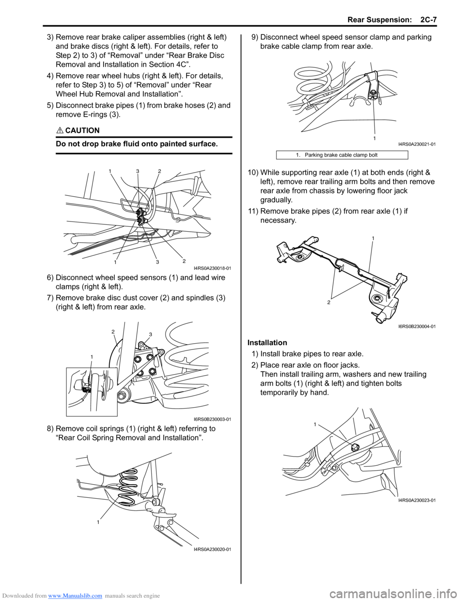
5) Disconnect brake pipes (1) from brake hoses (2) and remove E-rings (3).
CAUTION!
Do not drop brake fluid onto painted surface.
6) Disconnect wheel speed sensors (1) and lead wire clamps (right & left).
7) Remove brake disc dust cover (2) and spindles (3) (right & left) from rear axle.
8) Remove coil springs (1) (right & left) referring to “Rear Coil Spring Removal and Installation”. 9) Disconnect wheel speed sensor clamp and parking
brake cable clamp from rear axle.
10) While supporting rear axle (1) at both ends (right & left), remove rear trailing arm bolts and then remove
rear axle from chassis by lowering floor jack
gradually.
11) Remove brake pipes (2) from rear axle (1) if necessary.
Installation 1) Install brake pipes to rear axle.
2) Place rear axle on floor jacks. Then install trailing arm, washers and new trailing
arm bolts (1) (right & left) and tighten bolts
temporarily by hand.
1
1
2
2
3
3I4RS0A230018-01
1
2
3
I6RS0B230003-01
1
I4RS0A230020-01
1. Parking brake cable clamp bolt
1I4RS0A230021-01
2
1
I6RS0B230004-01
1
I4RS0A230023-01
Page 462 of 1496

Downloaded from www.Manualslib.com manuals search engine 2C-8 Rear Suspension:
3) Install coil springs (right & left) on spring seats of rear
axle referring to “Spring Upper Seat and Lower Seat
Removal and Installation” and “Rear Coil Spring
Removal and Installation”.
4) Install shock absorbers lower side (right & left) and washers referring to “Rear Shock Absorber Removal
and Installation”.
5) Install brake dust covers, spindles and wheel speed sensors (right and left) referring to “Spindle Removal
and Installation”.
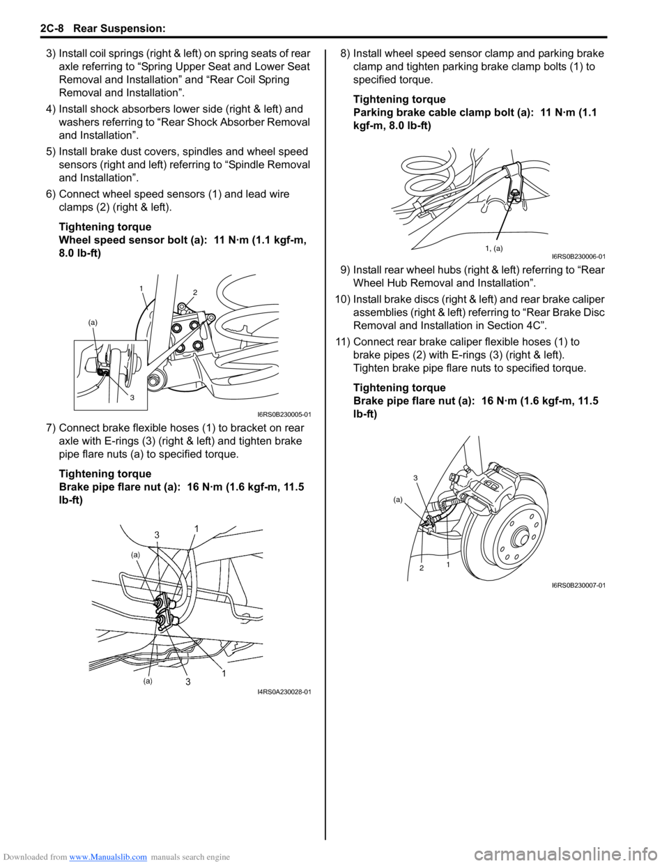
6) Connect wheel speed sensors (1) and lead wire clamps (2) (right & left).
Tightening torque
Wheel speed sensor bolt (a): 11 N·m (1.1 kgf-m,
8.0 lb-ft)
7) Connect brake flexible hoses (1) to bracket on rear axle with E-rings (3) (right & left) and tighten brake
pipe flare nuts (a) to specified torque.
Tightening torque
Brake pipe flare nut (a): 16 N·m (1.6 kgf-m, 11.5
lb-ft) 8) Install wheel speed sensor clamp and parking brake
clamp and tighten parking brake clamp bolts (1) to
specified torque.
Tightening torque
Parking brake cable clamp bolt (a): 11 N·m (1.1
kgf-m, 8.0 lb-ft)
9) Install rear wheel hubs (right & left) referring to “Rear Wheel Hub Removal and Installation”.
10) Install brake discs (right & left) and rear brake caliper assemblies (right & left) referring to “Rear Brake Disc
Removal and Installati on in Section 4C”.
11) Connect rear brake caliper flexible hoses (1) to brake pipes (2) with E-rings (3) (right & left).
Tighten brake pipe flare nuts to specified torque.
Tightening torque
Brake pipe flare nut (a): 16 N·m (1.6 kgf-m, 11.5
lb-ft)
1 2
(a)
3
I6RS0B230005-01
I4RS0A230028-01
1, (a)I6RS0B230006-01
3
2 1
(a)
I6RS0B230007-01
Page 479 of 1496

Downloaded from www.Manualslib.com manuals search engine Drive Shaft / Axle: 3A-1
Driveline / Axle
Drive Shaft / Axle
General Description
Front Drive Shaft ConstructionS7RS0B3101001
A constant velocity ball joint is used on the wheel side of both right and left side drive shaft assemblies. For A/T
vehicle, a tripod type constant velocity joint is used on the differential side and center shaft side. For M/T vehicle, a
double offset type constant velocity joint (DOJ) is used on the differential side and center shaft side. The drive shaft
can slide through the tripod joint or the double offset joint (DOJ) in the extension/contraction direction.
Component Location
Front Drive Shaft Assembly Components LocationS7RS0B3103001
I6RS0C310002-03
1. To transaxle 8. Ball stud washer : 45 N⋅m (4.5 kgf-m, 32.5 lb-ft)
2. Drive shaft assembly 9. Tie-rod end nut : 60 N⋅m (6.0 kgf-m, 43.5 lb-ft)
3. Tie-rod end 10. Ball stud bolt : 200 N⋅m (20.0 kgf-m, 145.0 lb-ft)
4. Center bearing support 11. Drive shaft nut
: After tightening nut, caulk nut securely. : 85 N
⋅m (8.5 kgf-m, 61.5 lb-ft)
5. Center shaft 12. Wheel nut : Do not reuse.
6. Center bearing support bolts 13. Drive shaft washer
7. Ball stud nut : 55 N⋅m (5.5 kgf-m, 40.0 lb-ft)
Page 517 of 1496
Downloaded from www.Manualslib.com manuals search engine Front Brakes: 4B-1
Brakes
Front Brakes
Repair Instructions
Front Disc Brake ComponentsS7RS0B4206001
11
5
6
10
4
1
16
17
12
8
7
3
2(a)
15
(b)
14(c)2(a)
13
(d)
9
FLD
I6RS0C420005-02
1. Caliper 9. Disk brake piston
: Apply brake fluid to contact surface of cylinder. 17. Brake flexible hose
2. Caliper pin bolt 10. Pad spring : 26 N⋅m (2.6 kgf-m, 19.0 lb-ft)
3. Boot 11. Brake disc: 23 N⋅m (2.3 kgf-m, 17.0 lb-ft)
4. Slide pin : Apply rubber grease (included in slide pin boot set). 12. Brake caliper carrier
: 8 N⋅m (0.8 kgf-m, 6.0 lb-ft)
5. Brake pad 13. Caliper carrier bolt : 85 N⋅m (8.5 kgf-m, 61.5 lb-ft)
6. Shim : Apply small amount of pad grease (include in pad
repair kit). 14. Bleeder plug
: Do not reuse.
7. Cylinder boot : Apply small amount of rubber grease included in
piston seal set. 15. Flexible hose joint bolt
8. Piston seal : Apply small amount of rubber grease included in
piston seal set. 16. Hose washer
Page 525 of 1496

Downloaded from www.Manualslib.com manuals search engine Rear Brakes: 4C-1
Brakes
Rear Brakes
Repair Instructions
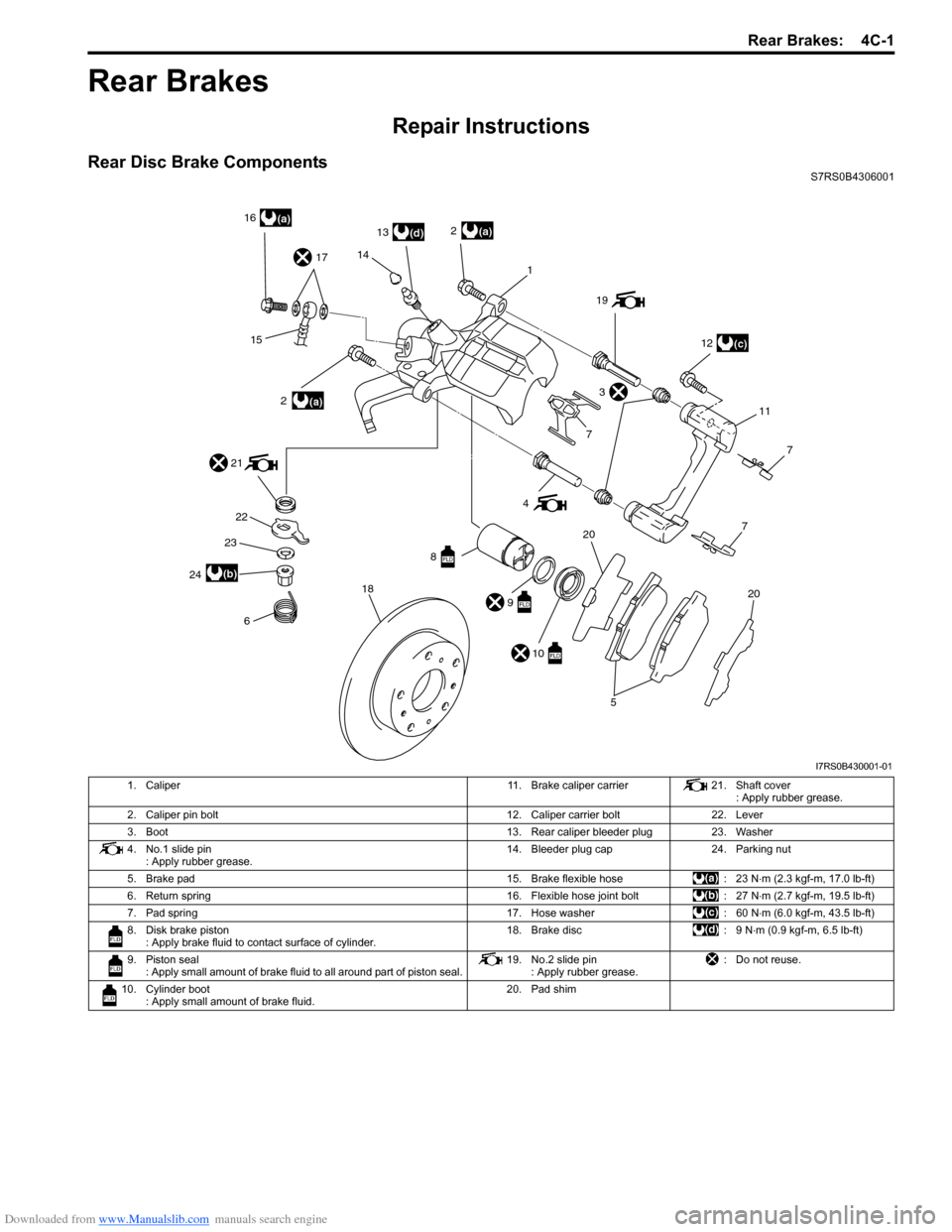
Rear Disc Brake ComponentsS7RS0B4306001
(d)
(c)
(a)
(a)
(a)16171413
2
1
15 2 19
12
117
7
3
7
4
20 20
5
10
9
8
(b)
18
6
24
23
22
21
I7RS0B430001-01
1. Caliper
11. Brake caliper carrier21. Shaft cover
: Apply rubber grease.
2. Caliper pin bolt 12. Caliper carrier bolt22. Lever
3. Boot 13. Rear caliper bleeder plug23. Washer
4. No.1 slide pin : Apply rubber grease. 14. Bleeder plug cap
24. Parking nut
5. Brake pad 15. Brake flexible hose: 23 N⋅m (2.3 kgf-m, 17.0 lb-ft)
6. Return spring 16. Flexible hose joint bolt: 27 N⋅m (2.7 kgf-m, 19.5 lb-ft)
7. Pad spring 17. Hose washer: 60 N⋅m (6.0 kgf-m, 43.5 lb-ft)
8. Disk brake piston : Apply brake fluid to contact surface of cylinder. 18. Brake disc
: 9 N⋅m (0.9 kgf-m, 6.5 lb-ft)
9. Piston seal : Apply small amount of brake fluid to all around part of piston seal. 19. No.2 slide pin
: Apply rubber grease. : Do not reuse.
10. Cylinder boot : Apply small amount of brake fluid. 20. Pad shim