2007 SUZUKI SWIFT input speed sensor
[x] Cancel search: input speed sensorPage 117 of 1496
Downloaded from www.Manualslib.com manuals search engine Engine General Information and Diagnosis: 1A-67
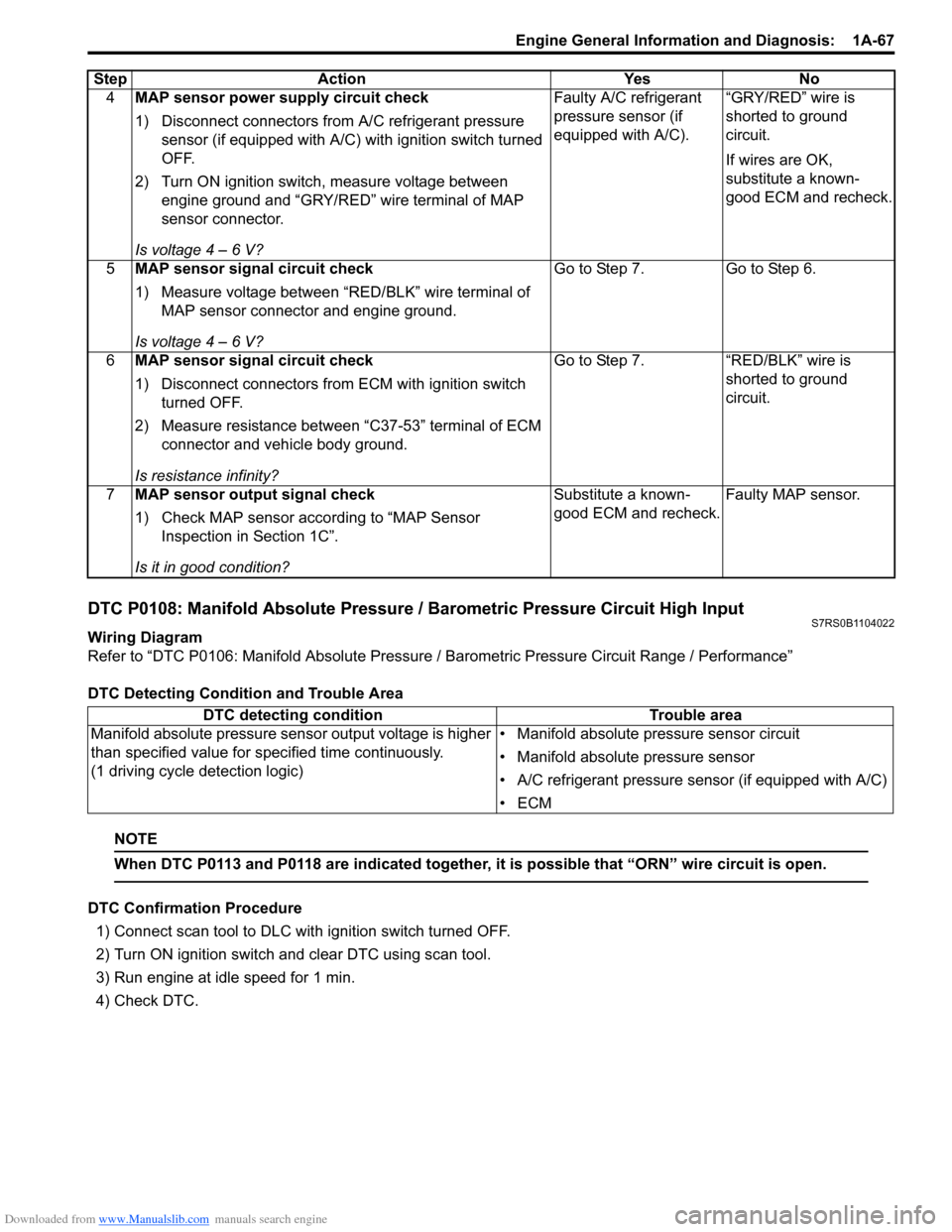
DTC P0108: Manifold Absolute Pressure / Barometric Pressure Circuit High InputS7RS0B1104022
Wiring Diagram
Refer to “DTC P0106: Manifold Absolute Pressure / Barometric Pressure Circuit Range / Performance”
DTC Detecting Condition and Trouble Area
NOTE
When DTC P0113 and P0118 are indicated together, it is possible that “ORN” wire circuit is open.
DTC Confirmation Procedure 1) Connect scan tool to DLC with ignition switch turned OFF.
2) Turn ON ignition switch and clear DTC using scan tool.
3) Run engine at idle speed for 1 min.
4) Check DTC. 4
MAP sensor power supply circuit check
1) Disconnect connectors from A/C refrigerant pressure
sensor (if equipped with A/C) with ignition switch turned
OFF.
2) Turn ON ignition switch, measure voltage between engine ground and “GRY/RED” wire terminal of MAP
sensor connector.
Is voltage 4 – 6 V? Faulty A/C refrigerant
pressure sensor (if
equipped with A/C).
“GRY/RED” wire is
shorted to ground
circuit.
If wires are OK,
substitute a known-
good ECM and recheck.
5 MAP sensor signal circuit check
1) Measure voltage between “RED/BLK” wire terminal of
MAP sensor connector and engine ground.
Is voltage 4 – 6 V? Go to Step 7. Go to Step 6.
6 MAP sensor signal circuit check
1) Disconnect connectors from ECM with ignition switch
turned OFF.
2) Measure resistance between “C37-53” terminal of ECM connector and vehicle body ground.
Is resistance infinity? Go to Step 7. “RED/BLK” wire is
shorted to ground
circuit.
7 MAP sensor output signal check
1) Check MAP sensor acco rding to “MAP Sensor
Inspection in Section 1C”.
Is it in good condition? Substitute a known-
good ECM and recheck.
Faulty MAP sensor.
Step Action Yes No
DTC detecting condition
Trouble area
Manifold absolute pressure sensor output voltage is higher
than specified value for s pecified time continuously.
(1 driving cycle detection logic) • Manifold absolute pressure sensor circuit
• Manifold absolute pressure sensor
• A/C refrigerant pressure sensor (if equipped with A/C)
•ECM
Page 179 of 1496
Downloaded from www.Manualslib.com manuals search engine Engine General Information and Diagnosis: 1A-129
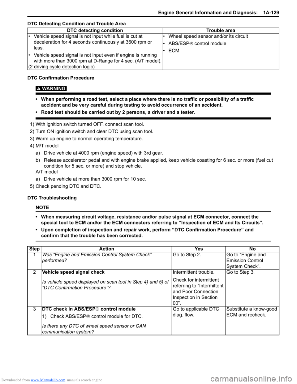
DTC Detecting Condition and Trouble Area
DTC Confirmation Procedure
WARNING!
• When performing a road test, select a place where there is no traffic or possibility of a traffic accident and be very careful during testing to avoid occurrence of an accident.
• Road test should be carried out by 2 persons, a driver and a tester.
1) With ignition switch turned OFF, connect scan tool.
2) Turn ON ignition switch and clear DTC using scan tool.
3) Warm up engine to normal operating temperature.
4) M/T model
a) Drive vehicle at 4000 rpm (e ngine speed) with 3rd gear.
b) Release accelerator pedal and with engine brake applied, keep vehicle coasting for 6 sec. or more (fuel cut condition for 5 sec. or more) and stop vehicle.
A/T model
a) Drive vehicle at more than 3000 rpm for 10 sec.
5) Check pending DTC and DTC.
DTC Troubleshooting
NOTE
• When measuring circuit voltage, resistance and/ or pulse signal at ECM connector, connect the
special tool to ECM and/or the ECM connectors re ferring to “Inspection of ECM and Its Circuits”.
• Upon completion of inspection and repair work, perform “DTC Confirmation Procedure” and confirm that the trouble has been corrected.
DTC detecting condition Trouble area
• Vehicle speed signal is not input while fuel is cut at deceleration for 4 seconds continuously at 3600 rpm or
less.
• Vehicle speed signal is not input even if engine is running with more than 3000 rpm at D-Range for 4 sec. (A/T model).
(2 driving cycle detection logic) • Wheel speed sensor and/or its circuit
• ABS/ESP®
control module
•ECM
Step Action YesNo
1 Was “Engine and Emission Control System Check”
performed? Go to Step 2.
Go to “Engine and
Emission Control
System Check”.
2 Vehicle speed signal check
Is vehicle speed displayed on scan tool in Step 4) and 5) of
“DTC Confirmation Procedure”? Intermittent trouble.
Check for intermittent
referring to “Intermittent
and Poor Connection
Inspection in Section
00”.Go to Step 3.
3 DTC check in ABS/ESP ® control module
1) Check ABS/ESP ® control module for DTC.
Is there any DTC of wheel speed sensor or CAN
communication system? Go to applicable DTC
diag. flow.
Substitute a know-good
ECM and recheck.
Page 302 of 1496
Downloaded from www.Manualslib.com manuals search engine 1D-17 Engine Mechanical:
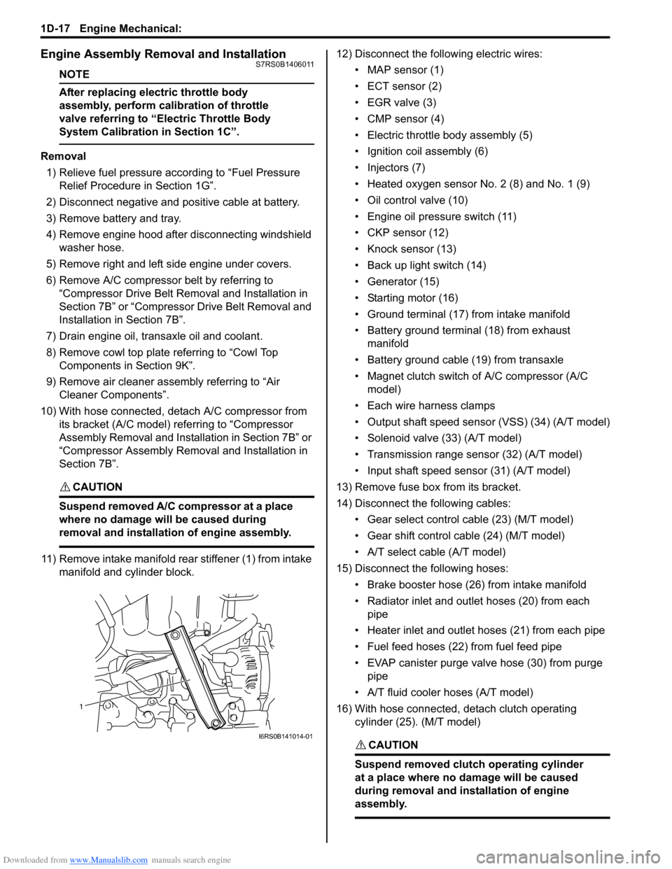
Engine Assembly Removal and InstallationS7RS0B1406011
NOTE
After replacing electric throttle body
assembly, perform calibration of throttle
valve referring to “Electric Throttle Body
System Calibration in Section 1C”.
Removal1) Relieve fuel pressure according to “Fuel Pressure Relief Procedure in Section 1G”.
2) Disconnect negative and pos itive cable at battery.
3) Remove battery and tray.
4) Remove engine hood after disconnecting windshield washer hose.
5) Remove right and left side engine under covers.
6) Remove A/C compressor belt by referring to “Compressor Drive Belt Remo val and Installation in
Section 7B” or “Compressor Drive Belt Removal and
Installation in Section 7B”.
7) Drain engine oil, transaxle oil and coolant.
8) Remove cowl top plate referring to “Cowl Top Components in Section 9K”.
9) Remove air cleaner assembly referring to “Air Cleaner Components”.
10) With hose connected, detach A/C compressor from its bracket (A/C model) referring to “Compressor
Assembly Removal and Installation in Section 7B” or
“Compressor Assembly Removal and Installation in
Section 7B”.
CAUTION!
Suspend removed A/C compressor at a place
where no damage will be caused during
removal and installation of engine assembly.
11) Remove intake manifold rear stiffener (1) from intake manifold and cylinder block. 12) Disconnect the following electric wires:
• MAP sensor (1)
• ECT sensor (2)
•EGR valve (3)
• CMP sensor (4)
• Electric throttle body assembly (5)
• Ignition coil assembly (6)
• Injectors (7)
• Heated oxygen sensor No. 2 (8) and No. 1 (9)
• Oil control valve (10)
• Engine oil pressure switch (11)
• CKP sensor (12)
• Knock sensor (13)
• Back up light switch (14)
• Generator (15)
• Starting motor (16)
• Ground terminal (17) from intake manifold
• Battery ground terminal (18) from exhaust manifold
• Battery ground cable (19) from transaxle
• Magnet clutch switch of A/C compressor (A/C model)
• Each wire harness clamps
• Output shaft speed sensor (VSS) (34) (A/T model)
• Solenoid valve (33) (A/T model)
• Transmission range sensor (32) (A/T model)
• Input shaft speed sensor (31) (A/T model)
13) Remove fuse box from its bracket.
14) Disconnect the following cables: • Gear select control cable (23) (M/T model)
• Gear shift control cable (24) (M/T model)
• A/T select cable (A/T model)
15) Disconnect the following hoses: • Brake booster hose (26) from intake manifold
• Radiator inlet and outlet hoses (20) from each pipe
• Heater inlet and outlet hoses (21) from each pipe
• Fuel feed hoses (22) from fuel feed pipe
• EVAP canister purge valve hose (30) from purge pipe
• A/T fluid cooler hoses (A/T model)
16) With hose connected, detach clutch operating cylinder (25). (M/T model)
CAUTION!
Suspend removed clutch operating cylinder
at a place where no damage will be caused
during removal and installation of engine
assembly.
1
I6RS0B141014-01
Page 543 of 1496
Downloaded from www.Manualslib.com manuals search engine ABS: 4E-4
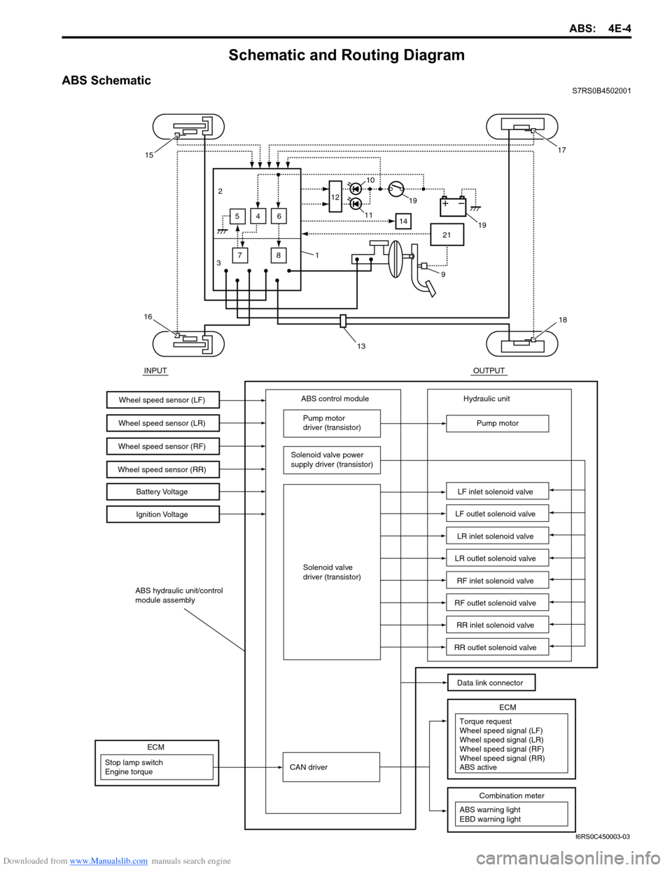
Schematic and Routing Diagram
ABS SchematicS7RS0B4502001
INPUTOUTPUT
ABS control moduleWheel speed sensor (LF)
Wheel speed sensor (LR)
Wheel speed sensor (RF)Battery Voltage
Ignition Voltage
Pump motor
driver (transistor)
Solenoid valve power
supply driver (transistor)
Solenoid valve
driver (transistor) Hydraulic unit
Pump motor
LF inlet solenoid valve
LF outlet solenoid valve
LR inlet solenoid valve
LR outlet solenoid valve
RF inlet solenoid valve
RF outlet solenoid valve
RR inlet solenoid valve
RR outlet solenoid valve
Data link connector
ABS hydraulic unit/control
module assembly
Wheel speed sensor (RR)
3 7
2
645
8 12
14
21
15
16
1
13
18
17
19
19
11
10
9
CAN driverStop lamp switch
Engine torque
ECM
ABS warning light
EBD warning light
Combination meter
Torque request
ECMWheel speed signal (LF)
Wheel speed signal (LR)
Wheel speed signal (RF)
Wheel speed signal (RR)
ABS active
I6RS0C450003-03
Page 551 of 1496

Downloaded from www.Manualslib.com manuals search engine ABS: 4E-12
DTC ClearanceS7RS0B4504006
WARNING!
When performing a driving test, select a safe
place where there is neither any traffic nor
any traffic accident possibility and be very
careful during testing to avoid occurrence of
an accident.
After repair or replace malfunction part(s), clear all DTCs
by performing the following procedure or using SUZUKI
scan tool.
1) Connect SUZUKI scan tool to data link connector in the same manner as when making this connection
for DTC check.
2) Turn ignition switch to ON position.
3) Erase DTC according to instructions displayed on scan tool. Refer to scan tool operator’s manual for
further derails.
NOTE
For DTC C 1021, C1022, C1025, C1026, C1031,
C1032, C1035, C1036 and C1061, confirm that
ABS warning light turns off after performing
Step 2 of “Test Driving” under “ABS Check”,
and then clear the DTCs.
4) After completing the clear ance, turn ignition switch
OFF and disconnect scan tool from data link
connector.
5) Perform “Driving Test” (S tep 2 of “ABS Check”) and
“DTC Check” and confirm that NO DTC is displayed
on scan tool.
Scan Tool DataS7RS0B4504007
The parameter data below are values measured with the
scan tool when the normally operating vehicle is under
the following conditions. When taking measurements for
comparison by using the scan tool, be sure to check that
the vehicle is under the following conditions.
• Apply parking brake and block wheels.
• Ignition switch ON.
• Turn OFF air conditioner (if equipped).
• Apply no load to power steering (if equipped). (Don’t turn it)
• Turn OFF all electric loads (except ignition).
• No DTC.
• ABS is not operated. (N ormal braking operation)
Scan Tool Data Definition
Battery Volt (V): Battery Voltage is an analog input
signal read by the ABS control module. Certain ABS
control module function s will be modified if the
battery voltage falls below or rises above
programmed thresholds.
Pump Motor Driver (V): This parameter indicates the
operational condition of the pump motor driver
(transistor).
RF Wheel Speed, LF Wheel Speed, RR Wheel Speed and LF Wheel Speed (km/h, MPH): Wheel speed
is an ABS control module inte rnal parameter. It is
computed by reference pulses from the wheel speed
sensor.
Brake Switch (ON, OFF): This switch signal informs
the ABS control modu le whether the brake is active
or not.
Scan Tool
Data Standards Condition
Battery
Voltage 10.0 – 18.0 V —
Pump Motor
Driver 0.0 V —
RF Wheel
Sp ee d 0 km/h, 0.0 MPH Vehicle stop
LF Wheel
Sp ee d 0 km/h, 0.0 MPH Vehicle stop
RR Wheel
Sp ee d 0 km/h, 0.0 MPH Vehicle stop
LR Wheel
Sp ee d 0 km/h, 0.0 MPH Vehicle stop
Brake Switch ONBrake pedal
depressed
OFF Brake pedal released
Page 557 of 1496
Downloaded from www.Manualslib.com manuals search engine ABS: 4E-18
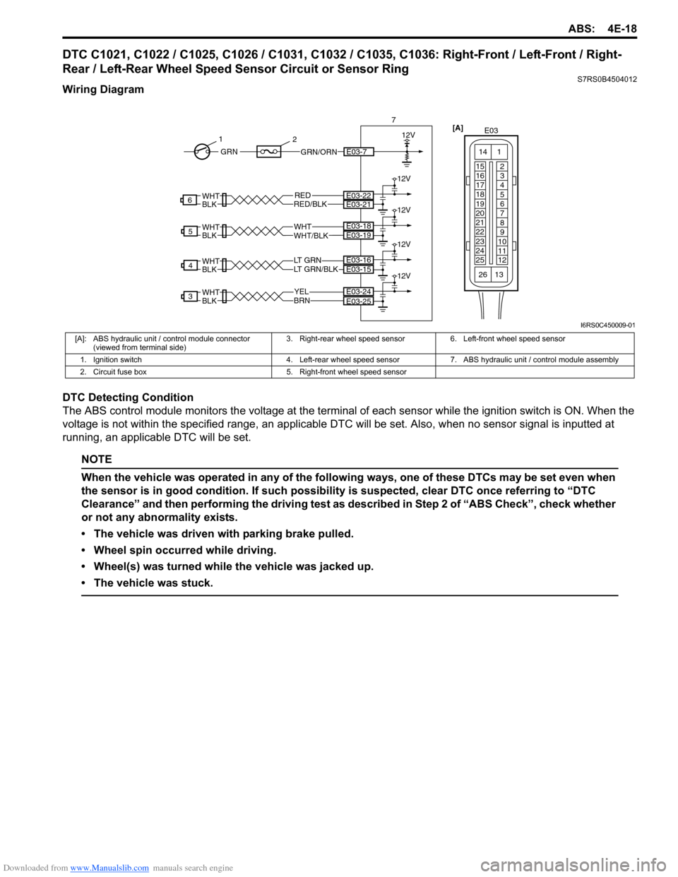
DTC C1021, C1022 / C1025, C1026 / C1031, C1032 / C1035, C1036: Right-Front / Left-Front / Right-
Rear / Left-Rear Wheel Speed Sensor Circuit or Sensor Ring
S7RS0B4504012
Wiring Diagram
DTC Detecting Condition
The ABS control module monitors the voltage at the terminal of each sensor while the ignition swit ch is ON. When the
voltage is not within the specified range, an applicable DTC will be set. Also, when no sensor signal is inputted at
running, an applicable DTC will be set.
NOTE
When the vehicle was operated in any of the following ways, one of these DTCs may be set even when
the sensor is in good condition. If such possibility is suspected, clear DTC once referring to “DTC
Clearance” and then performing the driving test as described in Step 2 of “ABS Check”, check whether
or not any abnormality exists.
• The vehicle was driven with parking brake pulled.
• Wheel spin occurred while driving.
• Wheel(s) was turned while the vehicle was jacked up.
• The vehicle was stuck.
YELBRN
3E03-24
LT GRN/BLKLT GRN
4
WHTWHT/BLK
5
RED
WHTBLK
WHTBLK
WHTBLK
WHTBLKRED/BLK
6
E03-25
E03-15E03-16
E03-19E03-18
E03-22E03-21
12V
12V
12V
12V
12V
7
GRN/ORNE03-7GRN
1
2
[A]
E03
15
16
17
18
19
20
21
22
23
24
25 2
3
4
5
6
7
8
9
10
11
12
1
13
14
26
I6RS0C450009-01
[A]: ABS hydraulic unit / control module connector
(viewed from terminal side) 3. Right-rear wheel speed sensor 6. Left-front wheel speed sensor
1. Ignition switch 4. Left-rear wheel speed sensor 7. ABS hydraulic unit / control module assembly
2. Circuit fuse box 5. Right-front wheel speed sensor
Page 579 of 1496
Downloaded from www.Manualslib.com manuals search engine Electronic Stability Program: 4F-5
Yaw rate / G sensor
The yaw rate / G sensor consists of the yaw rate (angular velocity in the vehicle turning direction) sensor and right-left
G (acceleration in right-left direction) sensor and is mounted to the P/S controller B/K at the lower part of the center
console. It detects the angular velocity in the vehicle turn ing direction and movement in the right-left direction, and
then it sends that information to ESP ® control module.
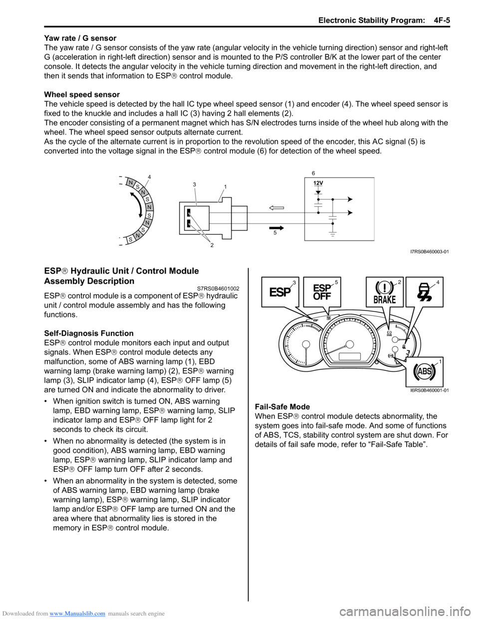
Wheel speed sensor
The vehicle speed is detected by the hall IC type wheel speed sensor (1) and encoder (4). The wheel speed sensor is
fixed to the knuckle and includes a hall IC (3) having 2 hall elements (2).
The encoder consisting of a permanent ma gnet which has S/N electrodes turns inside of the wheel hub along with the
wheel. The wheel speed sensor outputs alternate current.
As the cycle of the alternate current is in proportion to the revolution speed of the encoder, this AC signal (5) is
converted into the voltage signal in the ESP ® control module (6) for detection of the wheel speed.
ESP ® Hydraulic Unit / Control Module
Assembly Description
S7RS0B4601002
ESP ® control module is a component of ESP ® hydraulic
unit / control module assembly and has the following
functions.
Self-Diagnosis Function
ESP ® control module monitors each input and output
signals. When ESP ® control module detects any
malfunction, some of ABS warning lamp (1), EBD
warning lamp (brake warning lamp) (2), ESP ® warning
lamp (3), SLIP indicator lamp (4), ESP ® OFF lamp (5)
are turned ON and indicate the abnormality to driver.
• When ignition switch is turned ON, ABS warning lamp, EBD warning lamp, ESP ® warning lamp, SLIP
indicator lamp and ESP ® OFF lamp light for 2
seconds to check its circuit.
• When no abnormality is detected (the system is in good condition), ABS warning lamp, EBD warning
lamp, ESP ® warning lamp, SLIP indicator lamp and
ESP ® OFF lamp turn OFF after 2 seconds.
• When an abnormality in the system is detected, some of ABS warning lamp, EBD warning lamp (brake
warning lamp), ESP ® warning lamp, SLIP indicator
lamp and/or ESP ® OFF lamp are turned ON and the
area where that abnormality lies is stored in the
memory in ESP ® control module. Fail-Safe Mode
When ESP
® control module detects abnormality, the
system goes into fail-safe mode. And some of functions
of ABS, TCS, stability control system are shut down. For
details of fail safe mode, re fer to “Fail-Safe Table”.
S
N
S
N
S
N
N
S
N
S
12V
2
3
1
5
4
6I7RS0B460003-01
3245
1
I6RS0B460001-01
Page 582 of 1496
Downloaded from www.Manualslib.com manuals search engine 4F-8 Electronic Stability Program:
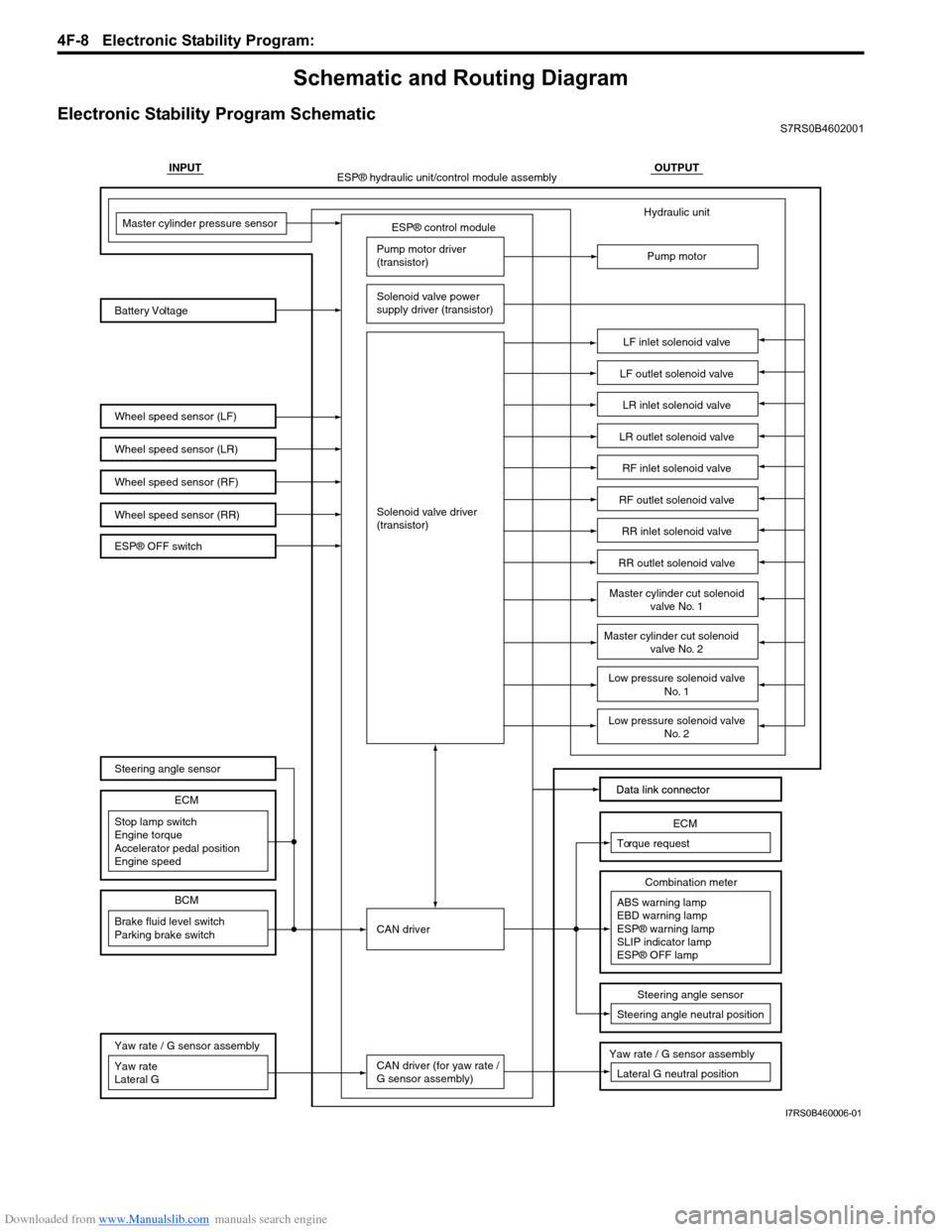
Schematic and Routing Diagram
Electronic Stability Program SchematicS7RS0B4602001
INPUTOUTPUT
ESP® control module
Wheel speed sensor (LF)
Wheel speed sensor (LR)
Wheel speed sensor (RF) Battery VoltageMaster cylinder pressure sensor
Pump motor driver
(transistor)
Solenoid valve power
supply driver (transistor)
Solenoid valve driver
(transistor)
CAN driver
CAN driver (for yaw rate /
G sensor assembly) Hydraulic unit
Pump motor
LF inlet solenoid valve
LF outlet solenoid valve
LR inlet solenoid valve
LR outlet solenoid valve
RF inlet solenoid valve
RF outlet solenoid valve
RR inlet solenoid valve
RR outlet solenoid valve
Data link connector
Data link connector
ESP® hydraulic unit/control module assembly
Wheel speed sensor (RR)
Master cylinder cut solenoid valve No. 1
Master cylinder cut solenoid
valve No. 2
Low pressure solenoid valve No. 1
Low pressure solenoid valveNo. 2
Stop lamp switch
Engine torque
Accelerator pedal position
Engine speed ECM
Brake fluid level switch
Parking brake switch
BCM
Steering angle sensor
ESP® OFF switch
Yaw rate
Lateral G Yaw rate / G sensor assembly
ABS warning lamp
EBD warning lamp
ESP® warning lamp
SLIP indicator lamp
ESP® OFF lampCombination meter
Torque request
ECM
Steering angle neutral positionSteering angle sensor
Yaw rate / G sensor assembly
Lateral G neutral position
I7RS0B460006-01