2007 SUZUKI SWIFT 7b-32
[x] Cancel search: 7b-32Page 933 of 1496
Downloaded from www.Manualslib.com manuals search engine Table of Contents 7- i
7
Section 7
CONTENTS
HVAC
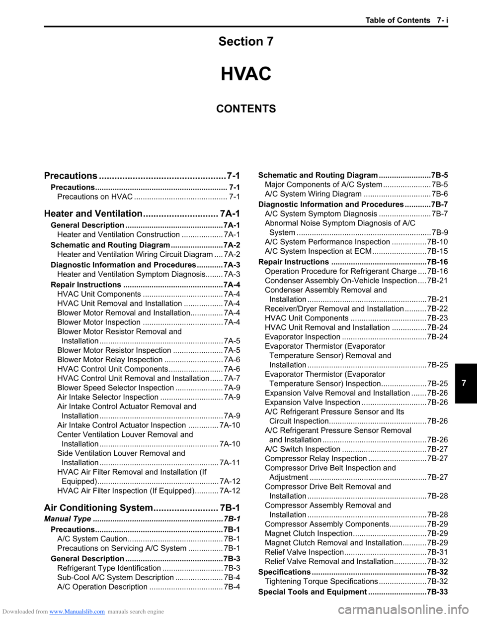
Precautions ................................................. 7-1
Precautions............................................................. 7-1
Precautions on HVAC ........................................... 7-1
Heater and Ventilation.... ......................... 7A-1
General Description ............................................. 7A-1
Heater and Ventilation Construction ................... 7A-1
Schematic and Routing Diagram ........................ 7A-2 Heater and Ventilation Wiring Circuit Diagram .... 7A-2
Diagnostic Information and Procedures ............ 7A-3 Heater and Ventilation Symptom Diagnosis........ 7A-3
Repair Instructions .............................................. 7A-4 HVAC Unit Components ..................................... 7A-4
HVAC Unit Removal and Installation .................. 7A-4
Blower Motor Removal and Installation............... 7A-4
Blower Motor Inspection ..................................... 7A-4
Blower Motor Resistor Removal and Installation ......................................................... 7A-5
Blower Motor Resistor Inspection ....................... 7A-5
Blower Motor Relay Inspection ........................... 7A-6
HVAC Control Unit Components ......................... 7A-6
HVAC Control Unit Remova l and Installation ...... 7A-7
Blower Speed Selector In spection ...................... 7A-9
Air Intake Selector Inspec tion ............................. 7A-9
Air Intake Control Actuator Removal and Installation ......................................................... 7A-9
Air Intake Control Actuator Inspection .............. 7A-10
Center Ventilation Louver Removal and Installation ....................................................... 7A-10
Side Ventilation Louver Removal and Installation ....................................................... 7A-11
HVAC Air Filter Removal and Installation (If Equipped)........................................................ 7A-12
HVAC Air Filter Inspection (If Equipped) ........... 7A-12
Air Conditioning System... ...................... 7B-1
Manual Type ............................................................ 7B-1
Precautions........................................................... 7B-1A/C System Caution ............................................ 7B-1
Precautions on Servicing A/C System ................ 7B-1
General Description ............................................. 7B-3 Refrigerant Type Identifica tion ............................ 7B-3
Sub-Cool A/C System Description ...................... 7B-4
A/C Operation Description .................................. 7B-4 Schematic and Routing Diagram ........................7B-5
Major Components of A/C System ...................... 7B-5
A/C System Wiring Diagram ............................... 7B-6
Diagnostic Information and Procedures ............7B-7 A/C System Symptom Diagnosis ........................ 7B-7
Abnormal Noise Sympto m Diagnosis of A/C
System .............................................................. 7B-9
A/C System Performance Inspection ................ 7B-10
A/C System Inspection at ECM ......................... 7B-15
Repair Instructions ........... .................................7B-16
Operation Procedure for Re frigerant Charge .... 7B-16
Condenser Assembly On-Vehicle Inspection .... 7B-21
Condenser Assembly Removal and Installation ....................................................... 7B-21
Receiver/Dryer Removal and Installation .......... 7B-22
HVAC Unit Components ................................... 7B-23
HVAC Unit Removal and In stallation ................ 7B-24
Evaporator Inspection ....................................... 7B-24
Evaporator Thermistor (Evaporator Temperature Sensor) Removal and
Installation ....................................................... 7B-25
Evaporator Thermistor (Evaporator Temperature Sensor) Inspec tion..................... 7B-25
Expansion Valve Removal and Installation ....... 7B-26
Expansion Valve Inspection .............................. 7B-26
A/C Refrigerant Pressure Sensor and Its Circuit Inspection............................................. 7B-26
A/C Refrigerant Pressu re Sensor Removal
and Installation ................................................ 7B-26
A/C Switch Inspection ....................................... 7B-27
Compressor Relay Inspection ........................... 7B-27
Compressor Drive Belt Inspection and Adjustment ...................................................... 7B-27
Compressor Drive Belt Removal and Installation ....................................................... 7B-28
Compressor Assembly Removal and Installation ....................................................... 7B-28
Compressor Assembly Components................. 7B-29
Magnet Clutch Inspection.................................. 7B-29
Magnet Clutch Removal and Installation........... 7B-29
Relief Valve Inspection...................................... 7B-31
Relief Valve Removal and Installation............... 7B-32
Specifications .................... .................................7B-32
Tightening Torque Specifications ...................... 7B-32
Special Tools and Equipmen t ...........................7B-33
Page 980 of 1496

Downloaded from www.Manualslib.com manuals search engine 7B-32 Air Conditioning System: Manual Type
Relief Valve Removal and InstallationS7RS0B7216030
Removal1) Recover refrigerant fr om the A/C system with
recovery and recycling equipment referring to
“Recovery” in “Operation Procedure for Refrigerant
Charge”.
2) Remove relief valve (1) from compressor (2). Installation
Reverse removal procedure nothing the following
instructions.
• Use new O-ring.
• Apply compressor oil to O-ring.
• Tighten relive valve to the specified torque.
Tightening torque
Relief valve (a): 8 N·m (0.8 kgf-m, 6.0 lb-ft)
• Evacuate and charge the A/C system referring to “Evacuation” and “Charge” in “Operation Procedure
for Refrigerant Charge”.
Specifications
Tightening Torque SpecificationsS7RS0B7217001
NOTE
The specified tightening torque is also described in the following.
“Compressor Assembly Components”
Reference:
For the tightening torque of fastener not specified in this section, refer to “Fasteners Information in Section 0A”.
12I4RS0A720048-01
(a)I4RS0A720049-01
Fastening part
Tightening torque
Note
N ⋅mkgf-mlb-ft
Receiver/dryer bolt 10 1.0 7.5 )
Expansion valve mount bolt 3.5 0.35 2.5 )
A/C refrigerant pressure sensor 11 1.1 8.0 )
Armature plate bolt 15 1.5 11.0 )
Relief valve 8 0.8 6.0 )