2007 SUZUKI SWIFT check engine
[x] Cancel search: check enginePage 19 of 1496
Downloaded from www.Manualslib.com manuals search engine Precautions: 00-14
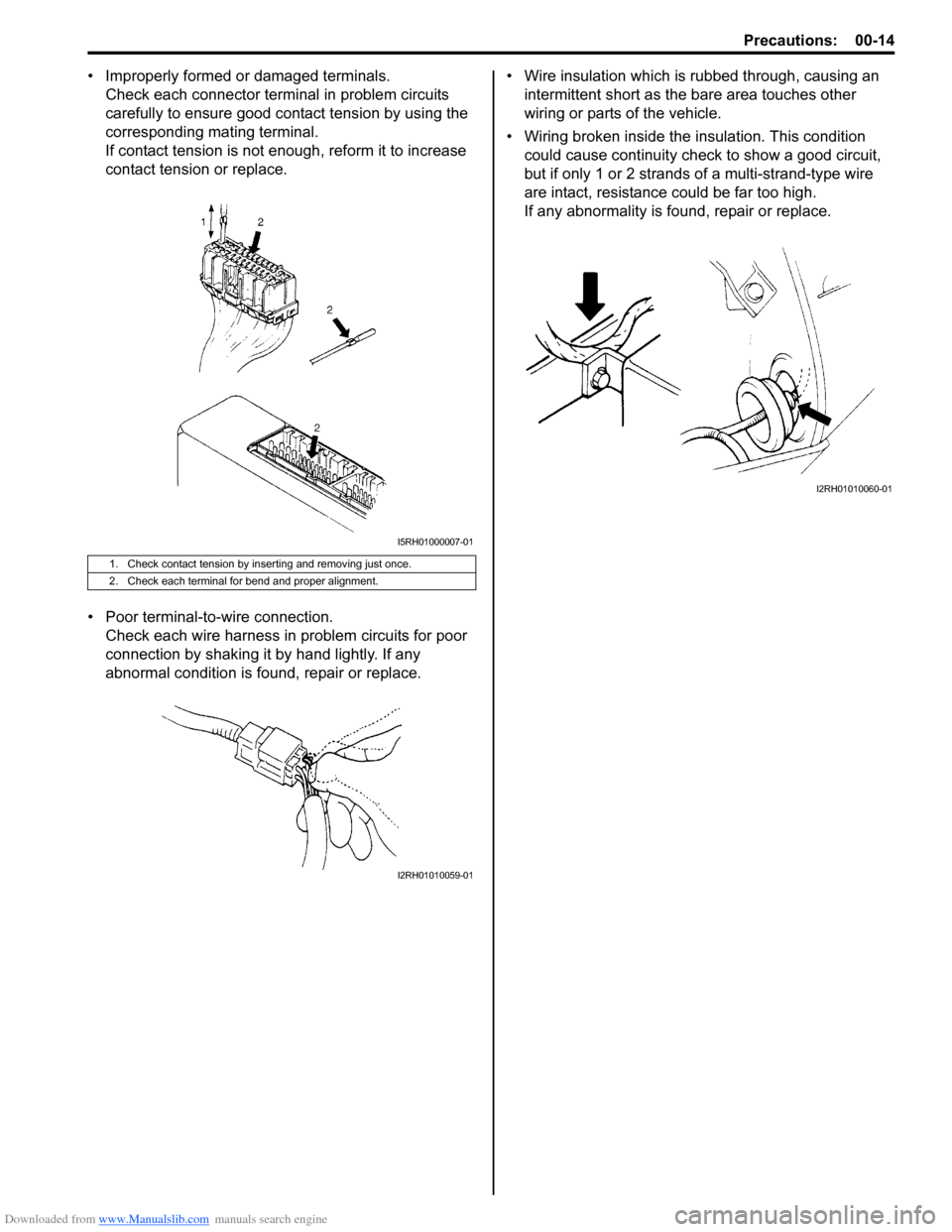
• Improperly formed or damaged terminals.Check each connector terminal in problem circuits
carefully to ensure good contact tension by using the
corresponding mating terminal.
If contact tension is not enough, reform it to increase
contact tension or replace.
• Poor terminal-to -wire connection.
Check each wire harness in problem circuits for poor
connection by shaking it by hand lightly. If any
abnormal condition is found, repair or replace. • Wire insulation which is rubbed through, causing an
intermittent short as the bare area touches other
wiring or parts of the vehicle.
• Wiring broken inside the insulation. This condition
could cause continuity check to show a good circuit,
but if only 1 or 2 strands of a multi-strand-type wire
are intact, resistance could be far too high.
If any abnormality is found, repair or replace.
1. Check contact tension by inserting and removing just once.
2. Check each terminal for bend and proper alignment.
I5RH01000007-01
I2RH01010059-01
I2RH01010060-01
Page 24 of 1496
Downloaded from www.Manualslib.com manuals search engine 0A-3 General Information:
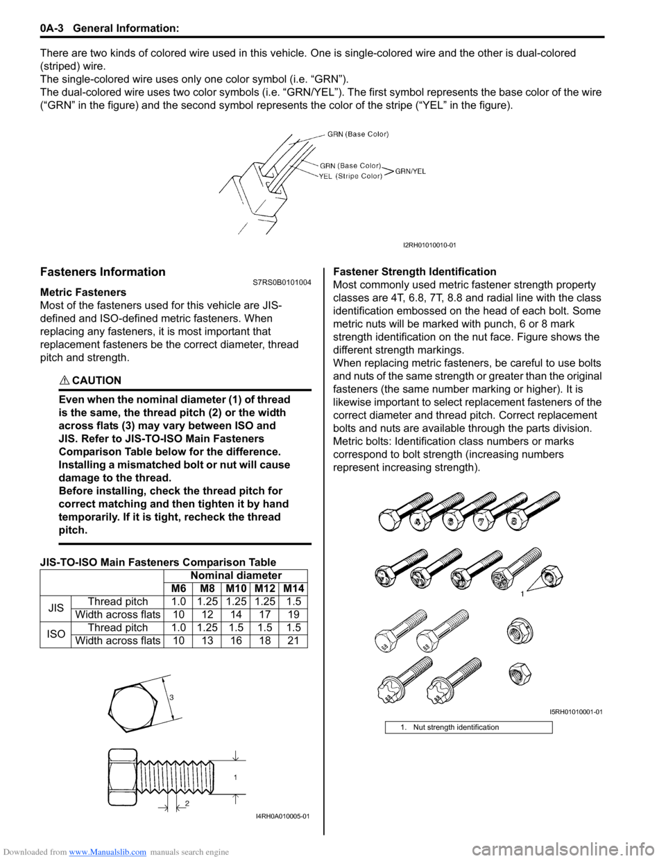
There are two kinds of colored wire used in this vehicle. One is single-colored wire and the other is dual-colored
(striped) wire.
The single-colored wire uses only one color symbol (i.e. “GRN”).
The dual-colored wire uses two color sy mbols (i.e. “GRN/YEL”). The first symbo l represents the base color of the wire
(“GRN” in the figure) and the second symbol represents the color of the stripe (“YEL” in the figure).
Fasteners InformationS7RS0B0101004
Metric Fasteners
Most of the fasteners used for this vehicle are JIS-
defined and ISO-defined metric fasteners. When
replacing any fasteners, it is most important that
replacement fasteners be the correct diameter, thread
pitch and strength.
CAUTION!
Even when the nominal diameter (1) of thread
is the same, the thread pitch (2) or the width
across flats (3) may vary between ISO and
JIS. Refer to JIS-TO-ISO Main Fasteners
Comparison Table below for the difference.
Installing a mismatched bolt or nut will cause
damage to the thread.
Before installing, check the thread pitch for
correct matching and then tighten it by hand
temporarily. If it is tight, recheck the thread
pitch.
JIS-TO-ISO Main Fasteners Comparison Table Fastener Strength Identification
Most commonly used metric fastener strength property
classes are 4T, 6.8, 7T, 8.8 and radial line with the class
identification embossed on the head of each bolt. Some
metric nuts will be marked with punch, 6 or 8 mark
strength identification on the nut face. Figure shows the
different strength markings.
When replacing metric fasteners, be careful to use bolts
and nuts of the same strength or greater than the original
fasteners (the same number marking or higher). It is
likewise important to select replacement fasteners of the
correct diameter and thread
pitch. Correct replacement
bolts and nuts are available through the parts division.
Metric bolts: Identification class numbers or marks
correspond to bolt strength (increasing numbers
represent increasing strength).
I2RH01010010-01
Nominal diameter
M6 M8 M10 M12 M14
JIS Thread pitch 1.0 1.25 1.25 1.25 1.5
Width across flats 10 12 14 17 19
ISO Thread pitch 1.0 1.25 1.5 1.5 1.5
Width across flats 10 13 16 18 21
I4RH0A010005-01
1. Nut strength identification
I5RH01010001-01
Page 26 of 1496

Downloaded from www.Manualslib.com manuals search engine 0A-5 General Information:
Vehicle Lifting PointsS7RS0B0101005
WARNING!
• Before applying hoist to underbody, always take vehicle balance throughout service into
consideration. Vehicle balance on hoist may change depending on what part to be removed.
• Before lifting up the vehicle, check to be sure that end of hoist arm is not in contact with brake pipe,
fuel pipe, bracket or any other part.
• When using frame contact hoist, apply hoist as shown (right and left at the same position). Lift up
the vehicle till 4 tires are a little off the ground and make sure that the vehicle will not fall off by
trying to move vehicle body in both ways. Work can be started only after this confirmation.
• Make absolutely sure to lock hoist after vehicle is hoisted up.
When Using Frame Contact Hoist
1
:2
:3
4
4
I4RS0A010001-01
1. Vehicle front
3. Floor jack position
2. Support position for frame contact hoist and safety stand 4. Body mounting stay
Page 27 of 1496
Downloaded from www.Manualslib.com manuals search engine General Information: 0A-6
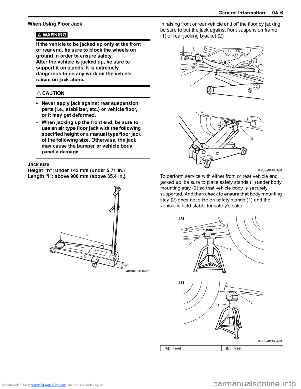
When Using Floor Jack
WARNING!
If the vehicle to be jacked up only at the front
or rear end, be sure to block the wheels on
ground in order to ensure safety.
After the vehicle is jacked up, be sure to
support it on stands. It is extremely
dangerous to do any work on the vehicle
raised on jack alone.
CAUTION!
• Never apply jack against rear suspension parts (i.e., stabilizer, etc.) or vehicle floor,
or it may get deformed.
• When jacking up the front end, be sure to use an air type floor jack with the following
specified height or a manual type floor jack
of the following size. Otherwise, the jack
may cause the bumper or vehicle body
panel a damage.
Jack size
Height “h”: under 145 mm (under 5.71 in.)
Length “l”: above 900 mm (above 35.4 in.) In raising front or rear vehicl
e end off the floor by jacking,
be sure to put the jack a gainst front suspension frame
(1) or rear jacking bracket (2).
To perform service with either front or rear vehicle end
jacked up, be sure to place safety stands (1) under body
mounting stay (2) so that vehicle body is securely
supported. And then check to ensure that body mounting
stay (2) does not slide on safety stands (1) and the
vehicle is held stable for safety’s sake.
“h”
“l”
I4RS0A010002-01
[A]: Front
[B]: Rear
2
1
I4RS0A010003-01
1
1
2
2
[B] [A]
I4RS0A010004-01
Page 33 of 1496

Downloaded from www.Manualslib.com manuals search engine Maintenance and Lubrication: 0B-3
NOTE
• “I”: Inspect and correct or replace if necessary
• “R”: Replace or change
• *1: Inspect or replace more frequently if the vehicle is used under dusty conditions.
• *2: Clean or replace more frequently if the air from the air conditioning decreases.
Repair Instructions
Accessory Drive Belt InspectionS7RS0B0206001
WARNING!
All inspection and replacement are to be
performed with ENGINE NOT RUNNING.
Water Pump and Generator Drive Belt1) Disconnect negative (–) cable at battery.
2) Inspect belt for cracks, cu ts, deformation, wear and
cleanliness. If any defect exists, replace.
Check belt for tension.
Water pump and generator belt tension
“a”: 4.5 – 5.5 mm (0.18 – 0.22 in.) deflection
under 100 N (10 kg, 22 lb) pressure
NOTE
When replacing belt with a new one, adjust
belt tension to 3.5 – 4 mm (0.14 – 0.16 in.)
3) If belt is too tight or too loose, adjust it to
specification by adjusting alternator position.
4) Tighten alternator adjusting bolts and pivot bolt.
5) Connect negative (–) cable to battery. A/C Compressor Drive Belt
1) Disconnect negative (–) cable at battery.
2) Inspect belt for cracks, cuts, deformation, wear and cleanliness. If any defect exists, replace.
Check belt for tension.
If belt tension is out of specification, adjust it
referring to “Compressor Dr ive Belt Inspection and
Adjustment in Section 7B”.
A/C compressor drive belt tension
“a”: 7 – 8 mm (0.28 – 0.31 in.) deflection under
100 N (10 kg, 22 lb) pressure
NOTE
When replacing belt with a new one, adjust
belt tension to 6 – 7 mm (0.24 – 0.28 in.).
3) Connect negative (–) cable to battery.
– B – – E – – H Automatic transaxle fluid
�) R Every 30,000 km (18,000 miles) or
24 months
– – C D – – – – HVAC air filter (if equipped) *2 �)
I Every 15,000 km (9,000 miles) or 12
months
�) R Every 45,000 km (27,000 miles) or
36 months
Severe
condition code MaintenanceMaintenance
operation Maintenance interval
I3RM0A020001-01
I4RS0A020001-01
Page 34 of 1496
Downloaded from www.Manualslib.com manuals search engine 0B-4 Maintenance and Lubrication:
Accessory Drive Belt ReplacementS7RS0B0206002
Water Pump and Generator Drive Belt
Replace belt with new one referring to “Water Pump /
Generator Drive Belt Removal and Installation in Section
1J”.
A/C Compressor Drive Belt
Replace belt with new one referring to “Compressor
Drive Belt Removal and Inst allation in Section 7B”.
Valve Lash (Clearance) InspectionS7RS0B0206003
Inspect intake and exhaust valve lash and adjust as
necessary.
Refer to “Valve Lash (Clearance) Inspection in Section
1D” for valve lash inspection and adjustment procedure.
Engine Oil and Filter ChangeS7RS0B0206004
WARNING!
• New and used engine oil can be
hazardous.
Be sure to read “WARNING” in “General
Precautions in Section 00” and observe
what is written there.
• Step 1) – 7) outlined below must be performed with ENGINE NOT RUNNING.
For Step 8), be sure to have adequate
ventilation while engine is running.
Before draining engine oil, check engine for oil leakage.
If any evidence of leakage is found, make sure to correct
defective part before proceeding to the following work.
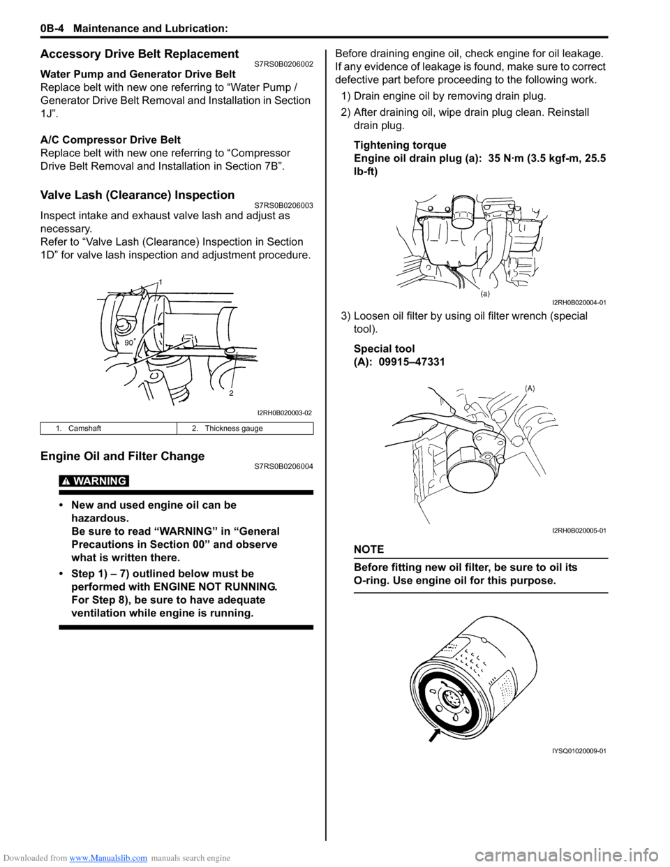
1) Drain engine oil by removing drain plug.
2) After draining oil, wipe drain plug clean. Reinstall drain plug.
Tightening torque
Engine oil drain plug (a): 35 N·m (3.5 kgf-m, 25.5
lb-ft)
3) Loosen oil filter by using oil filter wrench (special
tool).
Special tool
(A): 09915–47331
NOTE
Before fitting new oil filter, be sure to oil its
O-ring. Use engine oil for this purpose.
1. Camshaft 2. Thickness gauge
I2RH0B020003-02
I2RH0B020004-01
I2RH0B020005-01
IYSQ01020009-01
Page 35 of 1496
Downloaded from www.Manualslib.com manuals search engine Maintenance and Lubrication: 0B-5
4) Screw new filter on oil filter stand by hand until the filter O-ring contacts mounting surface.
CAUTION!
To tighten oil filter prop erly, it is important to
accurately identify the position at which filter
O-ring first contacts mounting surface.
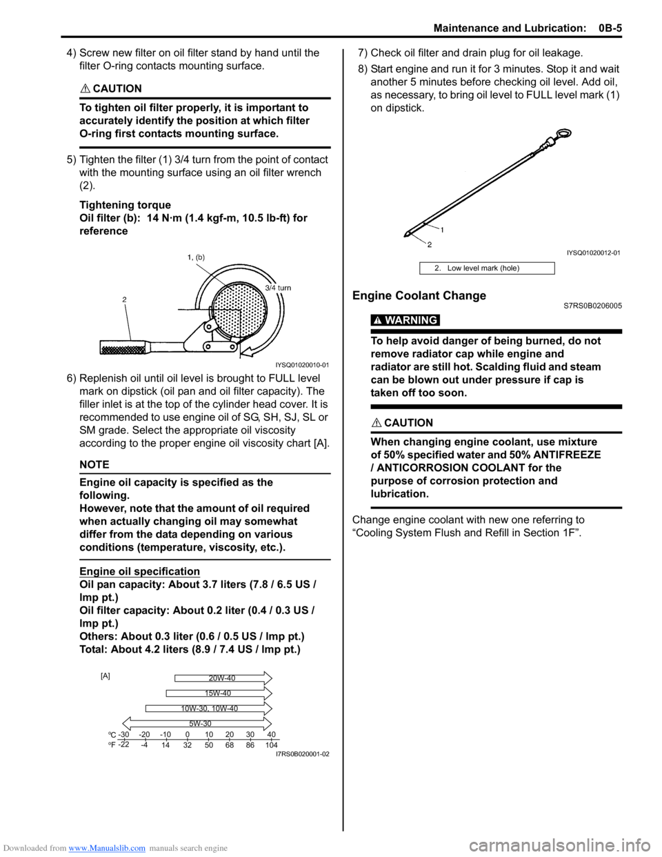
5) Tighten the filter (1) 3/4 tu rn from the point of contact
with the mounting surface using an oil filter wrench
(2).
Tightening torque
Oil filter (b): 14 N·m (1 .4 kgf-m, 10.5 lb-ft) for
reference
6) Replenish oil until oil leve l is brought to FULL level
mark on dipstick (oil pan and oil filter capacity). The
filler inlet is at the top of the cylinder head cover. It is
recommended to use engine oil of SG, SH, SJ, SL or
SM grade. Select the appropriate oil viscosity
according to the proper engine oil viscosity chart [A].
NOTE
Engine oil capacity is specified as the
following.
However, note that the amount of oil required
when actually changing oil may somewhat
differ from the data depending on various
conditions (temperature, viscosity, etc.).
Engine oil specification
Oil pan capacity: About 3.7 liters (7.8 / 6.5 US /
lmp pt.)
Oil filter capacity: About 0.2 liter (0.4 / 0.3 US /
lmp pt.)
Others: About 0.3 liter (0 .6 / 0.5 US / lmp pt.)
Total: About 4.2 liters (8.9 / 7.4 US / lmp pt.) 7) Check oil filter and drain plug for oil leakage.
8) Start engine and run it for 3 minutes. Stop it and wait
another 5 minutes before checking oil level. Add oil,
as necessary, to bring oil le vel to FULL level mark (1)
on dipstick.
Engine Coolant ChangeS7RS0B0206005
WARNING!
To help avoid danger of being burned, do not
remove radiator cap while engine and
radiator are still hot. Scalding fluid and steam
can be blown out under pressure if cap is
taken off too soon.
CAUTION!
When changing engine coolant, use mixture
of 50% specified water and 50% ANTIFREEZE
/ ANTICORROSION COOLANT for the
purpose of corrosion protection and
lubrication.
Change engine coolant with new one referring to
“Cooling System Flush and Refill in Section 1F”.
IYSQ01020010-01
Co
Fo-30
-22 -20
-4 -10
14 32 50 68 86 104 010203040
5W-30
20W-40
15W-40
10W-30, 10W-40
[A]
I7RS0B020001-02
2. Low level mark (hole)
IYSQ01020012-01
Page 36 of 1496
Downloaded from www.Manualslib.com manuals search engine 0B-6 Maintenance and Lubrication:
Exhaust System InspectionS7RS0B0206006
WARNING!
To avoid danger of being burned, do not
touch exhaust system when it is still hot.
Any service on exhaust system should be
performed when it is cool.
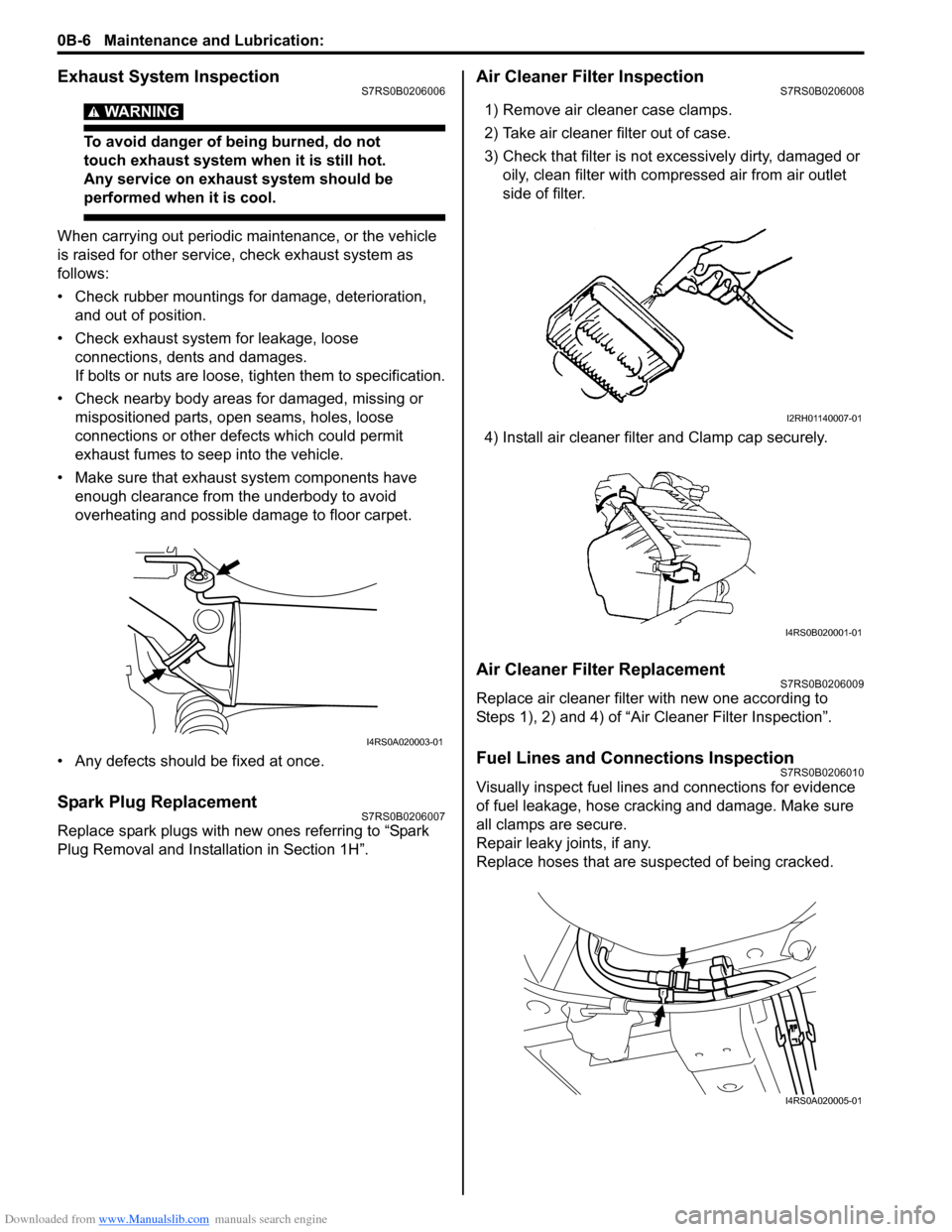
When carrying out periodic maintenance, or the vehicle
is raised for other service, check exhaust system as
follows:
• Check rubber mountings for damage, deterioration, and out of position.
• Check exhaust system for leakage, loose connections, dents and damages.
If bolts or nuts are loose, tighten them to specification.
• Check nearby body areas for damaged, missing or mispositioned parts, ope n seams, holes, loose
connections or other defects which could permit
exhaust fumes to seep into the vehicle.
• Make sure that exhaust system components have enough clearance from the underbody to avoid
overheating and possible damage to floor carpet.
• Any defects should be fixed at once.
Spark Plug ReplacementS7RS0B0206007
Replace spark plugs with new ones referring to “Spark
Plug Removal and Installation in Section 1H”.
Air Cleaner Filter InspectionS7RS0B0206008
1) Remove air cleaner case clamps.
2) Take air cleaner filter out of case.
3) Check that filter is not excessively dirty, damaged or oily, clean filter with compressed air from air outlet
side of filter.
4) Install air cleaner filter and Clamp cap securely.
Air Cleaner Filter ReplacementS7RS0B0206009
Replace air cleaner filter with new one according to
Steps 1), 2) and 4) of “Air Cleaner Filter Inspection”.
Fuel Lines and Connections InspectionS7RS0B0206010
Visually inspect fuel lines and connections for evidence
of fuel leakage, hose cracking and damage. Make sure
all clamps are secure.
Repair leaky joints, if any.
Replace hoses that are suspected of being cracked.
I4RS0A020003-01
I2RH01140007-01
I4RS0B020001-01
I4RS0A020005-01