2007 SUZUKI SWIFT Reverse light
[x] Cancel search: Reverse lightPage 831 of 1496

Downloaded from www.Manualslib.com manuals search engine Manual Transmission/Transaxle: 5B-17
5) Remove gear shift locating bolts (1) with washers,
then take out locating springs and steel balls.
6) Remove back up light switch (2).
7) Remove reverse shaft bolt (2) with washer.
8) Remove case bolts (1) from outside and another bolts from clutch housing side.
9) Tapping left case flanges with plastic hammer, remove left case (3).
10) Pull out reverse gear shaft (1) with washer (2), then take off reverse idler gear (3).
11) Remove reverse gear shift lever bolts (4) and reverse gear shift lever (5).
12) Pull out 5th & reverse gear shift guide shaft (6) together with 5th & reverse gear shift shaft (7). 13) Tapping input shaft end with plastic hammer, push it
out as assembly from case a little, then take out
input shaft assembly (1), countershaft assembly (2),
high speed gear shift shaft (3) and low speed gear
shift shaft (4) all at once.
14) Remove countershaft left bearing outer race from left case (1) using special tool.
Special tool
(A): 09913–70123
15) Remove side bearing retainer bolts.
16) Turn side bearing retainer (1) counterclockwise until it stops, and remove side bearing retainer using 2 flat
end rods (2) or the like.
17) Remove O-ring from side bearing retainer.
I2RH01520032-01
I4RS0A520032-01
I4RS0A520033-01
I2RH01520035-01
(A)
1
I4RH01520021-01
1
2
2
I4RS0A520034-01
Page 836 of 1496

Downloaded from www.Manualslib.com manuals search engine 5B-22 Manual Transmission/Transaxle:
14) With putting a shim (2) on bearing outer race (3), place straightedge (1) over it and compress it by
hand through straightedge, and then measure
clearance “a” between case surface (4) and
straightedge using feeler gauge (5).
Clearance between case surface and
straightedge (Shim protrusion)
“a”: 0.08 – 0.12 mm (0.0032 – 0.0047 in.)
15) By repeating Step 14), select a suitable shim which adjusts clearance “a” to specification and put it on
bearing outer race.
NOTE
Insert 0.10 mm (0.0039 in.) feeler to know
whether or not a shim fulfills specification
quickly.
Available shim thickness
16) Place left case plate (2) inserting its end in groove of shift guide shaft (4) and tighten bolts (1) to which
thread lock cement has been applied.
NOTE
After tightening bolts, make sure that
countershaft (5) can be rotated by hand
feeling certain load.
“A”: Thread lock cement 99000–32110 (Thread
Lock Cement Super 1322)
Tightening torque
Left case plate bolt (a): 23 N·m (2.3 kgf-m, 17.0
lb-ft)
17) Install fifth gear referring to “Fifth Gear Disassembly and Assembly”.
18) Install gear shift and select shaft assembly referring to “Gear Shift and Select Shaft Assembly Removal
and Installation”.
19) Install back up light switch referring to “Back Up Light
Switch Removal and Installation”.
20) Check input shaft for rotation in each gear position.
21) Also confirm continuity of back up light switch in
reverse position using ohmmeter.
0.55 mm (0.021 in.) 0.90 mm (0.035 in.)
0.60 mm (0.023 in.) 0.95 mm (0.037 in.)
0.65 mm (0.025 in.) 1.00 mm (0.039 in.)
0.70 mm (0.027 in.) 1.05 mm (0.041 in.)
0.75 mm (0.029 in.) 1.10 mm (0.043 in.)
0.80 mm (0.031 in.) 1.15 mm (0.059 in.)
0.85 mm (0.033 in.)
I3RM0A520031-01
3. Input shaft
I4RS0A520042-01
Page 849 of 1496

Downloaded from www.Manualslib.com manuals search engine Manual Transmission/Transaxle: 5B-35
6) Hold differential assembly with soft jawed vise (3),
install final gear (2) as shown in figure and then
tighten bolts (1) to specified torque.
CAUTION!
Use of any other bolts than specified ones is
prohibited.
Tightening torque
Final gear bolt (a): 90 N·m (9.0 kgf-m, 65.0 lb-ft)
Specifications
Tightening Torque SpecificationsS7RS0B5207001
NOTE
The specified tightening torque is also described in the following.
“Gear Shift Control Leve r and Cable Components”
“Manual Transaxle Unit Components”
“Gear Shift and Select Shaft Assembly Components”
“Manual Transaxle Assembly Components”
“Gear Shift Shaft Components”
“Differential Components”
Reference:
For the tightening torque of fastener not specified in this section, refer to “Fasteners Information in Section 0A”.
I4RS0A520043-01
Fastening part Tightening torque
Note
N ⋅mkgf-mlb-ft
Transaxle oil drain plug 21 2.1 15.5 �)
Transaxle oil level / filler plug 21 2.1 15.5 �)
Back up light switch 23 2.3 17.0 �)
Gear shift guide case bolt 23 2.3 17.0 �)
Select lever bracket bolt 23 2.3 17.0 �)
Gear shift interlock bolt 23 2.3 17.0 �)
5th to reverse interlock guide bolt 23 2.3 17.0 �)
Countershaft nut 100 10.0 72.5 �)
Shift fork bolt 10 1.0 7.5 �)
Side cover bolt 10 1.0 7.5 �)
Reverse gear shift lever bolt 23 2.3 17.0 �)
Reverse shaft bolt 23 2.3 17.0 �)
Transaxle case bolt 23 2.3 17.0 �)
Side bearing retainer bolt 23 2.3 17.0 �)
Gear shift locating bolt 13 1.3 9.5 �)
Left case plate bolt 23 2.3 17.0 �)
Oil gutter bolt 10 1.0 7.5 �)
Final gear bolt 90 9.0 65.0 �)
Page 855 of 1496

Downloaded from www.Manualslib.com manuals search engine Clutch: 5C-3
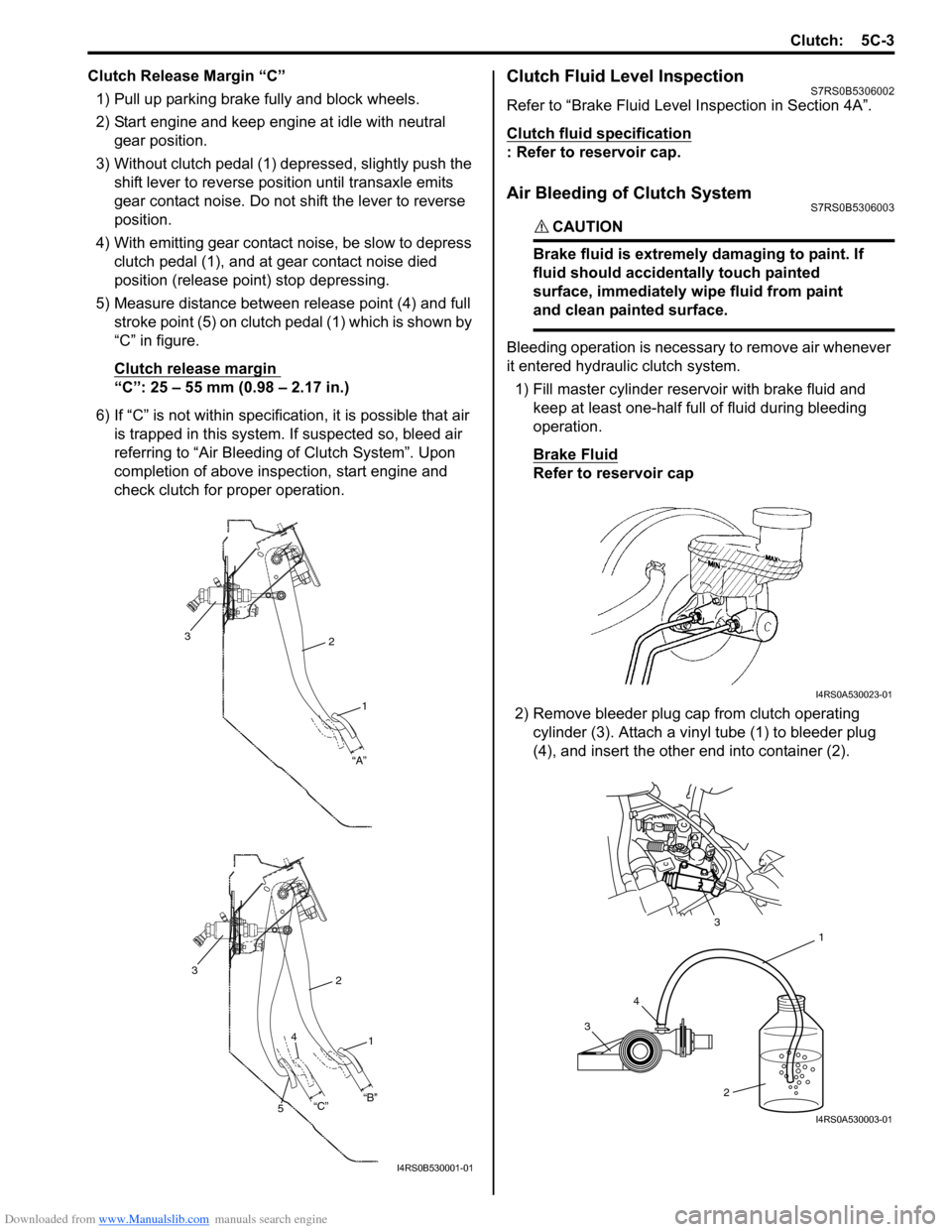
Clutch Release Margin “C”1) Pull up parking brake fully and block wheels.
2) Start engine and keep engine at idle with neutral gear position.
3) Without clutch pedal (1) dep ressed, slightly push the
shift lever to re verse position until transaxle emits
gear contact noise. Do not shift the lever to reverse
position.
4) With emitting gear contact noise, be slow to depress clutch pedal (1), and at gear contact noise died
position (release point) stop depressing.
5) Measure distance between release point (4) and full stroke point (5) on clutch pedal (1) which is shown by
“C” in figure.
Clutch release margin
“C”: 25 – 55 mm (0.98 – 2.17 in.)
6) If “C” is not within specificat ion, it is possible that air
is trapped in this system. If suspected so, bleed air
referring to “Air Bleeding of Clutch System”. Upon
completion of above inspection, start engine and
check clutch for proper operation.
Clutch Fluid Level InspectionS7RS0B5306002
Refer to “Brake Fluid Level Inspection in Section 4A”.
Clutch fluid specification
: Refer to reservoir cap.
Air Bleeding of Clutch SystemS7RS0B5306003
CAUTION!
Brake fluid is extremely damaging to paint. If
fluid should accidentally touch painted
surface, immediately wipe fluid from paint
and clean painted surface.
Bleeding operation is necessary to remove air whenever
it entered hydraulic clutch system.
1) Fill master cylinder reservoir with brake fluid and keep at least one-half full of fluid during bleeding
operation.
Brake Fluid
Refer to reservoir cap
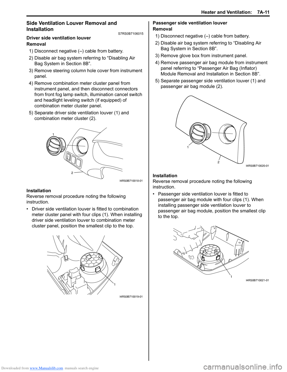
2) Remove bleeder plug cap from clutch operating cylinder (3). Attach a vinyl tube (1) to bleeder plug
(4), and insert the other end into container (2).
2
1
“A”
3
2
1
3
“B”
“C”
4
5
I4RS0B530001-01
I4RS0A530023-01
3 4 1
2
3
I4RS0A530003-01
Page 947 of 1496

Downloaded from www.Manualslib.com manuals search engine Heater and Ventilation: 7A-11
Side Ventilation Louver Removal and
Installation
S7RS0B7106015
Driver side ventilation louver
Removal1) Disconnect negative (–) cable from battery.
2) Disable air bag system referring to “Disabling Air Bag System in Section 8B”.
3) Remove steering column hol e cover from instrument
panel.
4) Remove combination meter cluster panel from instrument panel, and then disconnect connectors
from front fog lamp switch, illumination cancel switch
and headlight leveling switch (if equipped) of
combination meter cluster panel.
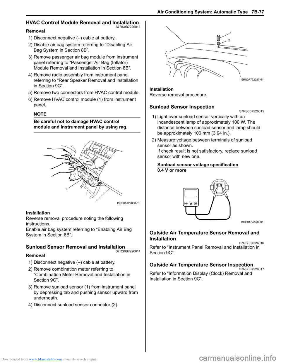
5) Separate driver side ventilation louver (1) and combination meter cluster (2).
Installation
Reverse removal procedure noting the following
instruction.
• Driver side ventilation louver is fitted to combination meter cluster panel with four clips (1). When installing
driver side ventilation louv er to combination meter
cluster panel, position the smallest clip to the top. Passenger side ventilation louver
Removal
1) Disconnect negative (–) cable from battery.
2) Disable air bag system referring to “Disabling Air Bag System in Section 8B”.
3) Remove glove box from instrument panel.
4) Remove passenger air bag module from instrument panel referring to “Passenger Air Bag (Inflator)
Module Removal and Installation in Section 8B”.
5) Separate passenger side ventilation louver (1) and passenger air bag module (2).
Installation
Reverse removal procedure noting the following
instruction.
• Passenger side ventilation louver is fitted to passenger air bag module with four clips (1). When
installing passenger side ventilation louver to
passenger air bag module, position the smallest clip
to the top.
2
1
I4RS0B710018-01
1
I4RS0B710019-01
2
1
I4RS0B710020-01
1I4RS0B710021-01
Page 958 of 1496

Downloaded from www.Manualslib.com manuals search engine 7B-10 Air Conditioning System: Manual Type
Abnormal Noise from Tension Pulley
Abnormal Noise from A/C Evaporator
Abnormal Noise from Blower Motor
A/C System Performance InspectionS7RS0B7214003
1) Confirm that vehicle and environmental conditions are as follows.
• Vehicle is put indoors.
• Ambient temperature is within 25 – 35 °C (77 – 95
° F).
• Relative humidity is within 30 – 70%.
• There is no wind indoors.
• HVAC unit is normal.
• Blower motor is normal.
• There is no air leakage from air ducts.
• Condenser fins are clean.
• Air filter in HVAC unit is not clogged with dirt and
dust.
• Battery voltage is about 12 V.
• Radiator cooling fan operates normally.
2) Make sure that high pressure valve (1) and low pressure valve (2) of manifold gauge are firmly
closed.
3) Connect high pressure charging hose (3) to high pressure service valve (5) on vehicle and low
pressure charging hose (4) to low pressure service
valve (6).
4) Bleed the air in charging hoses (3) and (4) by loosening their nuts respectively utilizing the
refrigerant pressure. When a hissing sound is heard,
immediately tighten nut.
CAUTION!
Do not connect high and low pressure
charging hoses in reverse.
Condition Possible cause Correction / Reference Item
Clattering noise is heard
from pulley Worn or damaged bearing
Replace tension pulley.
Pulley cranks upon
contact Cracked or loose bracket
Replace or retighten bracket.
ConditionPossible cause Correction / Reference Item
Whistling sound is heard
from A/C evaporator Depending on the combination of the
interior / exterior temperatures, engine
rpm and refrigerant pressure, the
refrigerant flowing out of the expansion
valve may, under certain conditions,
make a whistling sound At times, slightly decrea
sing refrigerant volume
may stop this noise.
Inspect expansion valve and replace if faulty.
Condition Possible cause Correction / Reference Item
Blower motor emits a
chirping sound in
proportion to its speed of
rotation Worn or damaged motor brushes or
commutator
Replace blower motor.
Fluttering noise or large
droning noise is heard
from blower motor Leaves or other debris introduced from
fresh air inlet to blower motor
Remove debris and make sure that the screen
at fresh air inlet is intact.
53
2
1
4 6
I4RS0A720006-01
Page 1025 of 1496

Downloaded from www.Manualslib.com manuals search engine Air Conditioning System: Automatic Type 7B-77
HVAC Control Module Removal and InstallationS7RS0B7226013
Removal1) Disconnect negative (–) cable at battery.
2) Disable air bag system referring to “Disabling Air Bag System in Section 8B”.
3) Remove passenger air bag module from instrument panel referring to “Passenger Air Bag (Inflator)
Module Removal and Installation in Section 8B”.
4) Remove radio assembly from instrument panel referring to “Rear Speaker Removal and Installation
in Section 9C”.
5) Remove two connectors fr om HVAC control module.
6) Remove HVAC control modu le (1) from instrument
panel.
NOTE
Be careful not to damage HVAC control
module and instrument panel by using rag.
Installation
Reverse removal procedure noting the following
instructions.
Enable air bag system referring to “Enabling Air Bag
System in Section 8B”.
Sunload Sensor Removal and InstallationS7RS0B7226014
Removal
1) Disconnect negative (–) cable at battery.
2) Remove combination meter referring to “Combination Meter Removal and Installation in
Section 9C”.
3) Remove sunload sensor (1) from instrument panel by depressing tab and pushing sensor upward from
underneath.
4) Disconnect sunload sensor connector (2). Installation
Reverse removal procedure.
Sunload Sensor InspectionS7RS0B7226015
1) Light over sunload sensor vertically with an
incandescent lamp of approximately 100 W. The
distance between sunload sensor and lamp should
be approximately 100 mm (3.94 in.).
2) Measure voltage between terminals of sunload sensor as shown.
If check result is not satisfactory, replace sunload
sensor with new one.
Sunload sensor voltage specification
0.4 V or more
Outside Air Temperature Sensor Removal and
Installation
S7RS0B7226016
Refer to “Instrument Panel Re moval and Installation in
Section 9C”.
Outside Air Temperature Sensor InspectionS7RS0B7226017
Refer to “Information Display (Clock) Removal and
Installation in Section 9C”.
1
I5RS0A722030-01
1
2
I5RS0A722027-01
I4RH01722036-01
Page 1257 of 1496

Downloaded from www.Manualslib.com manuals search engine Wiring Systems: 9A-86
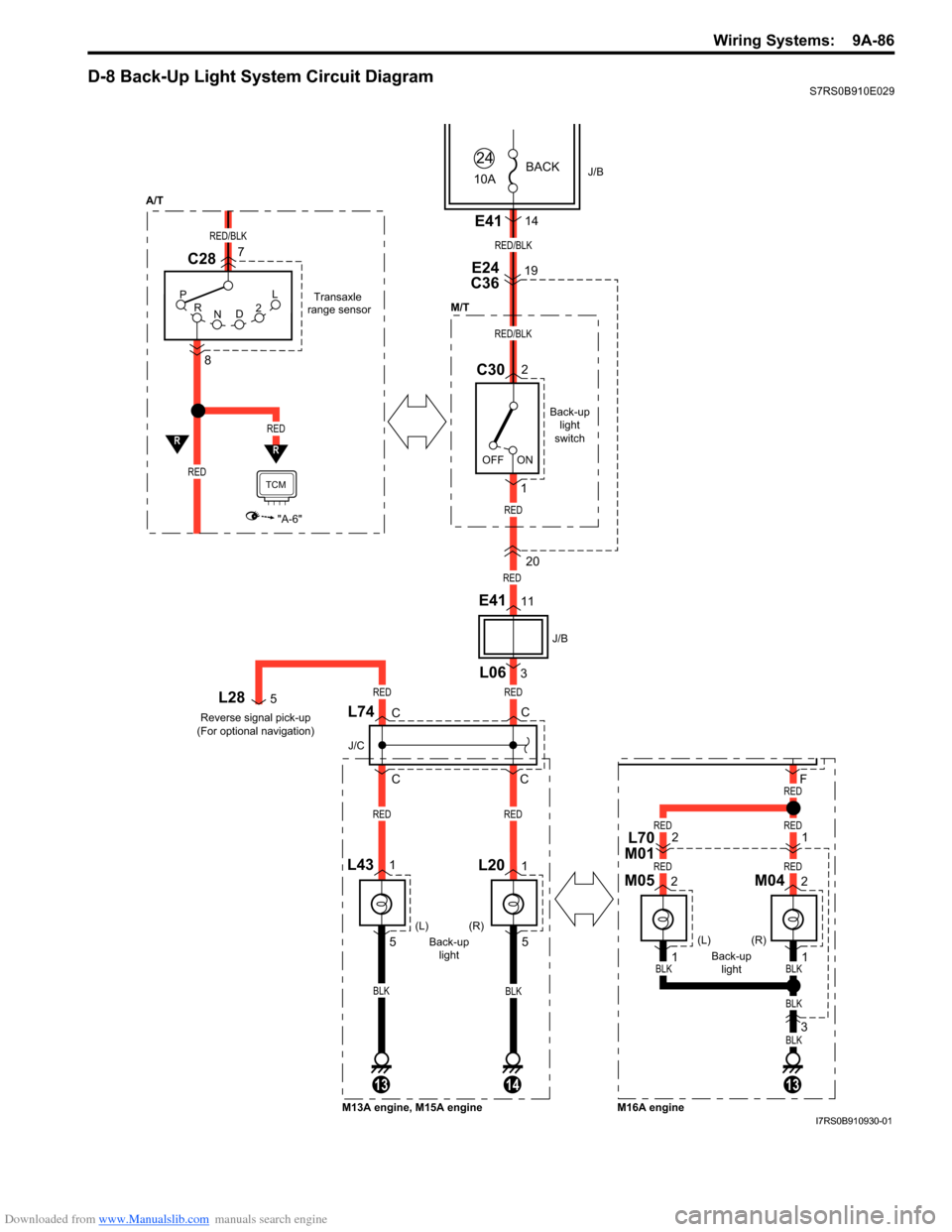
D-8 Back-Up Light System Circuit DiagramS7RS0B910E029
BLKBLK
141313
CC
C
J/C
L74CL28
Back-up light
switch
Back-up light (R)
RED
RED
RED/BLK
RED/BLK
ON
OFF J/B
10A
24BACK
E24
C3619
C302
1 20
L431L201
RED
RED
RED
M/T
L063
E4111
J/B
P R N D2LTransaxle
range sensor
RED/BLK
C28
R
RED
8
RED
"A-6"
TCM
R
E4114
7
5 5
Reverse signal pick-up
(For optional navigation)
5RED
(L)
Back-uplight (R)
(L)
M13A engine, M15A engine M16A engine
BLK
BLK
BLKBLK
F
M042
RED
REDRED
REDRED
1
M052
1
1L70
M012
3
A/T
I7RS0B910930-01